EP2105259A2 - Appareil d'entraînement - Google Patents
Appareil d'entraînement Download PDFInfo
- Publication number
- EP2105259A2 EP2105259A2 EP09154266A EP09154266A EP2105259A2 EP 2105259 A2 EP2105259 A2 EP 2105259A2 EP 09154266 A EP09154266 A EP 09154266A EP 09154266 A EP09154266 A EP 09154266A EP 2105259 A2 EP2105259 A2 EP 2105259A2
- Authority
- EP
- European Patent Office
- Prior art keywords
- magazine
- mouth part
- latching
- housing
- setting tool
- Prior art date
- Legal status (The legal status is an assumption and is not a legal conclusion. Google has not performed a legal analysis and makes no representation as to the accuracy of the status listed.)
- Granted
Links
Images

Classifications
-
- B—PERFORMING OPERATIONS; TRANSPORTING
- B25—HAND TOOLS; PORTABLE POWER-DRIVEN TOOLS; MANIPULATORS
- B25C—HAND-HELD NAILING OR STAPLING TOOLS; MANUALLY OPERATED PORTABLE STAPLING TOOLS
- B25C1/00—Hand-held nailing tools; Nail feeding devices
- B25C1/08—Hand-held nailing tools; Nail feeding devices operated by combustion pressure
- B25C1/10—Hand-held nailing tools; Nail feeding devices operated by combustion pressure generated by detonation of a cartridge
- B25C1/18—Details and accessories, e.g. splinter guards, spall minimisers
- B25C1/182—Feeding devices
- B25C1/184—Feeding devices for nails
-
- F—MECHANICAL ENGINEERING; LIGHTING; HEATING; WEAPONS; BLASTING
- F41—WEAPONS
- F41A—FUNCTIONAL FEATURES OR DETAILS COMMON TO BOTH SMALLARMS AND ORDNANCE, e.g. CANNONS; MOUNTINGS FOR SMALLARMS OR ORDNANCE
- F41A17/00—Safety arrangements, e.g. safeties
- F41A17/34—Magazine safeties
- F41A17/38—Magazine mountings, e.g. for locking the magazine in the gun
Definitions
- the present invention relates to a setting tool referred to in the preamble of claim 1.
- Art Such setting tools can be operated with solid, gaseous or liquid fuels, with compressed or compressed air or electrical energy.
- the propellant body In such setting tools, in which a propellant such as a setting piston or plunger drives the fastener into the ground, the propellant body is accelerated in the direction of the fastener.
- the combustion-driven setting tools of the propellant body z. B. driven by the combustion gases. By the pressure acting on the propellant body, this is accelerated in the direction of a fastener, meets this and drives the element into the ground.
- the fasteners can be stored in a magazine that is arranged in the region of a mouth part of the setting device.
- the object of the present invention is therefore to develop a setting tool of the aforementioned type, which avoids the aforementioned disadvantages, allows easy attachment of the magazine to the housing and a possible close seal to the housing out, which complicates a dirt entry into the magazine.
- the connecting means have a latching closure acting between the magazine and the housing, which has a latching member and a counter-latching element, which can be brought into a latching position, wherein the latching closure in the latching position presses the magazine against the muzzle part.
- the magazine is on the one hand quickly mounted, since the connecting means designed as a snap closure snaps in the manner of a snap connection when pressing the magazine against the housing of the setting tool automatically and connects the magazine with the housing.
- the latching closure on at least partially along a longitudinal extent of the magazine displaceable and acted upon by at least one elastic element slide (on one of the parts of the housing and magazine), which carries the locking member, wherein the acted upon by the elastic member slide in the locking position the Magazine presses against the mouth part.
- at least partially displaceable in the longitudinal direction of the magazine slide a relatively high pressure force of the magazine can be achieved against the mouth part.
- the counter-latching element is arranged on the other part of housing and magazine.
- the slider is arranged on the magazine and elastically acted upon by the at least one elastic element in a direction away from the connecting portion of the magazine, wherein the locking member facing away from the connecting portion and the housing facing the end of the slider and the counter-latching element on the housing is arranged.
- the slider could alternatively be arranged on the housing of the setting device.
- further connecting means are provided between the mouth part and the magazine, which comprise a pivot bearing with a pivot axis on the side facing away from the housing of the magazine, wherein the pivot axis outside the mouth part and outside of the magazine and at a right angle to a defined by the bolt guide and the magazine level lies.
- the pivot bearing has a curved bearing surface on the connecting portion and a complementary curved counter-bearing surface on the mouth part.
- the radii of curvature of the curved bearing surface and the curved abutment surface are the same.
- the bearing surface is concave and the abutment surface convexly curved, which allows for the attachment of the magazine at the mouth part pivoting of the magazine to the housing of the setting device.
- Optimum tuning of the pivot bearing is achieved when the bearing surface and the abutment surface in each case a bow angle [alpha1], [alpha2] spanning from a minimum of 25 ° to a maximum of 185 °.
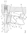
- the setting device 10 is z. B. electrically or combustion-powered and has a arranged in a housing 11 network with a setting as a piston driving body 13 which is guided in a guide 12 displaceable.
- the propellant body is shown in its initial position, in which the propellant body 13 is ready for a setting process.
- bolt guide 15 Coaxially to the guide 12 extending a arranged on a mouth part 14 bolt guide 15 is arranged on the setting tool 10, which is facing away from the housing 11 free end to a workpiece attachable.
- the bolt guide 15 serves to receive and guide fasteners 50 (indicated in FIG Fig. 1 A fastening element 50 located in the bolt guide 15 is driven into a workpiece during a setting process via the drive element 13 moving in the direction of the free end of the bolt guide 15 (not shown in the figures) ).
- a magazine designated as a whole with 20 is releasably arranged on the setting tool 10.
- a guide channel 24 is arranged for fastening elements 50 which is open to the bolt guide 15, so that in the Fig. 1 It can be seen on the setting device 10 fixed position of the magazine 20, a transport of fasteners 50 from the guide channel 24 in the pin guide 15 is possible.
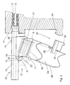
- the magazine 20 has a connection section 21 designed as a connecting piece, which has a concave bearing surface 22 on a first narrow side 25, which together with a convex abutment surface 19 forms a pivot bearing 17 on a bearing block 18 of the mouth part 14, its pivot bearing axis S outside of the mouth part 14 and outside of the magazine 20 and at a right angle to a through the bolt guide 15 and the Magazine 20 defined level E lies.
- the bearing surface 22 and the abutment surface 19 are curved complementary to each other, and span an arc angle [alpha1], [alpha2] from a minimum of 25 ° to a maximum of 185 ° (see Fig. 1 ), to ensure optimum guidance of the surfaces to each other.
- the pivot bearing 17 is arranged on the side facing away from the housing 11 of the magazine 20.
- the magazine 20 is supported in the driving direction of the drive body 13 and in a direction perpendicular to the longitudinal extent of the bolt guide 15 relative to the mouth portion 14.
- the first narrow side 25 of the connecting portion 21 and the magazine 20 with the concave bearing surface 22 is disposed opposite a second narrow side 26 of the connecting portion 21 and the magazine 20.
- a stop A is arranged in the region of the connecting portion 21, which rests in the setting device 10 fixed state of the magazine 20 at one edge of the mouth part 14 and over which the magazine 20 in one of the driving direction of the drive body 13 opposite direction relative to the Mouth part 14 is supported.
- a slide 31 of a latching closure is also arranged so as to be displaceable in a limited manner along a longitudinal extension of the at least partially straight magazine 20.
- the slider 31 is via at least one elastic element 32, such as. As a spring element, in a sliding direction away from the connecting portion 21 of the magazine 20 elastically acted upon.
- the slide 31 has at its end facing away from the connecting portion 21 at least one locking member 33, which with a counter-latching element 34 of the latching closure 30 on the housing 11 in a Fig. 1 apparent locking position 35 can be brought.
- the magazine 20 is securely fixed on the setting device 10 via the pivot bearing 17 in combination with the latching closure 30.
- the magazine 20 is acted upon in a direction perpendicular to the bolt guide 15 and pressed towards the mouth part 14, so that a seam 23 between the mouth part 14 and the bolt guide 15 on the one hand and the connecting portion 21 of the magazine 20 on the other is tightly closed.
- no particles can pass through the opening of the guide channel 24 into the magazine 20 and also not into the magazine 20 open towards the bolt guide 15.
- the slider 31 is manually displaced against the force of the at least one elastic element 32 in the direction of the arrow 70 into an unlocking position 36, as in FIG Fig. 1 represented by the dashed lines shown slider 31.
- the magazine 20 can now around the pivot bearing 17 with the virtual, located outside of the mouth part 14 and outside the magazine 20 pivot axis S around in the direction of the pivot arrow 71 (see Figures 2 and 3 ) are pivoted until the magazine 20 is completely detached from the mouth part 14 and free.
- this process is carried out in the opposite pivoting direction until the latching closure 30 closes and the locking member 33 engages the counter-latching element 34.
Landscapes
- Engineering & Computer Science (AREA)
- Chemical & Material Sciences (AREA)
- Combustion & Propulsion (AREA)
- Mechanical Engineering (AREA)
- General Engineering & Computer Science (AREA)
- Portable Nailing Machines And Staplers (AREA)
- Aiming, Guidance, Guns With A Light Source, Armor, Camouflage, And Targets (AREA)
- Connection Of Plates (AREA)
- Structures Of Non-Positive Displacement Pumps (AREA)
Applications Claiming Priority (1)
| Application Number | Priority Date | Filing Date | Title |
|---|---|---|---|
| DE102008000831A DE102008000831A1 (de) | 2008-03-26 | 2008-03-26 | Setzgerät |
Publications (3)
| Publication Number | Publication Date |
|---|---|
| EP2105259A2 true EP2105259A2 (fr) | 2009-09-30 |
| EP2105259A3 EP2105259A3 (fr) | 2010-06-23 |
| EP2105259B1 EP2105259B1 (fr) | 2011-06-15 |
Family
ID=40800494
Family Applications (1)
| Application Number | Title | Priority Date | Filing Date |
|---|---|---|---|
| EP09154266A Active EP2105259B1 (fr) | 2008-03-26 | 2009-03-04 | Appareil d'entraînement |
Country Status (5)
| Country | Link |
|---|---|
| US (2) | US7959049B2 (fr) |
| EP (1) | EP2105259B1 (fr) |
| JP (1) | JP5268727B2 (fr) |
| DE (1) | DE102008000831A1 (fr) |
| ES (1) | ES2364023T3 (fr) |
Cited By (3)
| Publication number | Priority date | Publication date | Assignee | Title |
|---|---|---|---|---|
| US10987790B2 (en) | 2016-06-30 | 2021-04-27 | Black & Decker Inc. | Cordless concrete nailer with improved power take-off mechanism |
| US11267114B2 (en) | 2016-06-29 | 2022-03-08 | Black & Decker, Inc. | Single-motion magazine retention for fastening tools |
| US11325235B2 (en) | 2016-06-28 | 2022-05-10 | Black & Decker, Inc. | Push-on support member for fastening tools |
Families Citing this family (23)
| Publication number | Priority date | Publication date | Assignee | Title |
|---|---|---|---|---|
| US8312667B2 (en) * | 2009-01-14 | 2012-11-20 | Premier Reticles, Ltd | Lockable adjustment mechanism |
| US7937879B2 (en) * | 2009-03-11 | 2011-05-10 | Sheltered Wings, Inc. | Rifle scope with a low-light visible element |
| US8166696B2 (en) | 2009-09-14 | 2012-05-01 | Sheltered Wings, Inc. | Rifle scope with adjustment stop |
| US8166697B1 (en) * | 2010-06-22 | 2012-05-01 | Sueskind Alan E | Rifle scope indicia system |
| US8713843B2 (en) | 2011-01-16 | 2014-05-06 | Bernard T. Windauer | Operator-programmable-trajectory turret knob |
| DE202012002286U1 (de) * | 2012-03-08 | 2013-06-10 | Carl Zeiss Sports Optics Gmbh | Betätigungselement für die Verstellung oder Einstellung eines Parameters eines optischen Geräts, insbesondere Absehenschnellverstellung für ein Zielfernrohr |
| US8919026B2 (en) | 2012-04-18 | 2014-12-30 | Sheltered Wings, Inc. | Rifle scope turret with spiral cam mechanism |
| US9677848B2 (en) | 2012-04-18 | 2017-06-13 | Sheltered Wings, Inc. | Multiple knob turret |
| WO2014145226A1 (fr) * | 2013-03-15 | 2014-09-18 | Huskemaw Optics, Llc | Système de tourelles à verrouillage mutuel |
| US10591253B1 (en) | 2013-03-15 | 2020-03-17 | Tangent Theta Inc. | Finger-adjustable scope adjustment mechanism |
| CN203566643U (zh) * | 2013-11-21 | 2014-04-30 | 浙江荣鹏气动工具有限公司 | 一种快卸式三合一气动斜钉枪 |
| US11105587B2 (en) | 2016-01-27 | 2021-08-31 | Sheltered Wings, Inc. | Turret with a zero stop |
| US11279013B2 (en) | 2016-06-30 | 2022-03-22 | Black & Decker, Inc. | Driver rebound plate for a fastening tool |
| US11400572B2 (en) | 2016-06-30 | 2022-08-02 | Black & Decker, Inc. | Dry-fire bypass for a fastening tool |
| USD807983S1 (en) * | 2016-08-12 | 2018-01-16 | All Pro Sporting Goods Inc. | Scope |
| US10926385B2 (en) | 2017-02-24 | 2021-02-23 | Black & Decker, Inc. | Contact trip having magnetic filter |
| EP3501747A1 (fr) * | 2017-12-21 | 2019-06-26 | HILTI Aktiengesellschaft | Dispositif d'enfoncement |
| US11906268B2 (en) | 2019-02-27 | 2024-02-20 | Leupold & Stevens, Inc. | Tool-less re-zero adjustment knob for aiming devices, and methods of zeroing an aiming device |
| CN116235019A (zh) | 2020-06-16 | 2023-06-06 | 夏尔特银斯公司D.B.A.涡流光学 | 具有归零锁定的转台 |
| EP4237201A4 (fr) | 2020-10-30 | 2024-12-11 | Milwaukee Electric Tool Corporation | Dispositif d'entraînement d'élément de fixation motorisé |
| JP7795644B2 (ja) | 2022-02-21 | 2026-01-07 | キョウセラ センコ インダストリアル ツールズ インク. | 締結具駆動工具用のマガジン締結具ガイド |
| WO2024186547A1 (fr) | 2023-03-06 | 2024-09-12 | Leupold & Stevens, Inc. | Assemblage de bouton sans outil pour dispositif optique |
| CN121625055A (zh) | 2024-08-28 | 2026-03-10 | 株式会社牧田 | 打入工具 |
Citations (1)
| Publication number | Priority date | Publication date | Assignee | Title |
|---|---|---|---|---|
| DE3337278A1 (de) | 1983-10-13 | 1985-04-25 | Metabowerke GmbH & Co, 7440 Nürtingen | Eintreibgeraet |
Family Cites Families (22)
| Publication number | Priority date | Publication date | Assignee | Title |
|---|---|---|---|---|
| US3670941A (en) * | 1970-03-02 | 1972-06-20 | Fred I Grinnell | Retractable guard and guide for nailer |
| US3739973A (en) * | 1971-06-30 | 1973-06-19 | Arrow Fastener Co Inc | Stapling machine |
| US3834602A (en) * | 1973-01-26 | 1974-09-10 | Fastener Corp | Fastener driving tool |
| US3840165A (en) * | 1973-08-15 | 1974-10-08 | Signode Corp | Magazine release mechanism for fastener driving tool |
| US3883064A (en) * | 1974-03-29 | 1975-05-13 | Thomas M Hilgers | Bracket setting tool |
| US4286388A (en) * | 1976-10-29 | 1981-09-01 | W. R. Weaver Company | Sight with reduced friction line of sight adjustment |
| US4389012A (en) * | 1981-04-22 | 1983-06-21 | Duo-Fast Corporation | Fastener tool loading assembly |
| US4566621A (en) * | 1984-07-03 | 1986-01-28 | Sencorp | Means for associating a driver, constituting a part of a replaceable fastener containing magazine, with the driver operating mechanism of a fastener driving tool |
| US4671443A (en) * | 1984-07-03 | 1987-06-09 | Sencorp | Replaceable magazine system for a fastener driving tool |
| DE3426173A1 (de) * | 1984-07-16 | 1986-01-23 | Hilti Ag, Schaan | Eintreibgeraet fuer befestigungselemente, wie naegel, klammern und dergleichen |
| US4648531A (en) * | 1985-03-05 | 1987-03-10 | Ben Clements & Sons, Inc. | Dispenser for bag closures |
| US4806007A (en) * | 1987-11-06 | 1989-02-21 | Armson, Inc. | Optical gun sight |
| US5025968A (en) * | 1989-06-19 | 1991-06-25 | Duo-Fast Corporation | Furniture tool |
| JPH0723169Y2 (ja) * | 1991-01-18 | 1995-05-31 | マックス株式会社 | 釘打機におけるマガジン取付構造 |
| TW424653U (en) * | 1999-10-30 | 2001-03-01 | Jins Industry Corp | Improved structure for nail housing cartridge of nailing gun |
| JP2002120167A (ja) * | 2000-10-13 | 2002-04-23 | Max Co Ltd | 釘打ち機 |
| US6431428B1 (en) * | 2000-10-16 | 2002-08-13 | Jui-Chin Chen | Pneumatic nail gun |
| US6640481B1 (en) * | 2002-08-05 | 2003-11-04 | John B. Williams, Jr. | Externally adjustable rifle telescope |
| US7025242B1 (en) * | 2002-09-18 | 2006-04-11 | Black & Decker Inc. | Adjustable angle magazine |
| ITBO20030105A1 (it) * | 2003-02-28 | 2004-09-01 | Fasco Spa | Pistola pneumatica per elementi di fissaggio. |
| US7440185B1 (en) * | 2005-12-15 | 2008-10-21 | Raytheon Company | Method and apparatus for internally zeroing a sight |
| US7640830B2 (en) * | 2007-08-19 | 2010-01-05 | Bonis James G | Locking adjustment turret |
-
2008
- 2008-03-26 DE DE102008000831A patent/DE102008000831A1/de not_active Withdrawn
-
2009
- 2009-03-04 ES ES09154266T patent/ES2364023T3/es active Active
- 2009-03-04 EP EP09154266A patent/EP2105259B1/fr active Active
- 2009-03-10 US US12/381,355 patent/US7959049B2/en active Active
- 2009-03-11 US US12/381,325 patent/US7958665B2/en active Active
- 2009-03-23 JP JP2009070349A patent/JP5268727B2/ja active Active
Patent Citations (1)
| Publication number | Priority date | Publication date | Assignee | Title |
|---|---|---|---|---|
| DE3337278A1 (de) | 1983-10-13 | 1985-04-25 | Metabowerke GmbH & Co, 7440 Nürtingen | Eintreibgeraet |
Cited By (3)
| Publication number | Priority date | Publication date | Assignee | Title |
|---|---|---|---|---|
| US11325235B2 (en) | 2016-06-28 | 2022-05-10 | Black & Decker, Inc. | Push-on support member for fastening tools |
| US11267114B2 (en) | 2016-06-29 | 2022-03-08 | Black & Decker, Inc. | Single-motion magazine retention for fastening tools |
| US10987790B2 (en) | 2016-06-30 | 2021-04-27 | Black & Decker Inc. | Cordless concrete nailer with improved power take-off mechanism |
Also Published As
| Publication number | Publication date |
|---|---|
| US20090241399A1 (en) | 2009-10-01 |
| EP2105259B1 (fr) | 2011-06-15 |
| US20090242606A1 (en) | 2009-10-01 |
| EP2105259A3 (fr) | 2010-06-23 |
| DE102008000831A1 (de) | 2009-10-01 |
| JP5268727B2 (ja) | 2013-08-21 |
| US7958665B2 (en) | 2011-06-14 |
| ES2364023T3 (es) | 2011-08-23 |
| JP2009233848A (ja) | 2009-10-15 |
| US7959049B2 (en) | 2011-06-14 |
Similar Documents
| Publication | Publication Date | Title |
|---|---|---|
| EP2105259B1 (fr) | Appareil d'entraînement | |
| EP2105258B1 (fr) | Appareil de pose | |
| DE102012207571B4 (de) | Abdeckvorrichtung mit Staubabsaugung bei Verwendung mit einem Elektrowerkzeug | |
| DE3245359A1 (de) | Saege, insbesondere motorisch angetriebene handstichsaege | |
| DE3436020A1 (de) | Mit hilfsleistung angetriebene befestigungsteil-setzmaschine (tacker) mit sicherheitseinrichtung | |
| DE202011104615U1 (de) | Verschluss für Sterilcontainer | |
| DE3426173A1 (de) | Eintreibgeraet fuer befestigungselemente, wie naegel, klammern und dergleichen | |
| DE102005044128A1 (de) | Handwerkzeug | |
| DE102010040780A1 (de) | Eintreibvorrichtung für Befestigungsmittel mit einer Leerabschussverriegelungsvorrichtung | |
| DE2809791C2 (de) | Vorrichtung zum Bündeln mehrerer Gegenstände, insbesondere elektrischer Kabel, mit einem Spannband | |
| DE3105951A1 (de) | "kraftwerkzeug" | |
| DE19749027B4 (de) | Setzgerät | |
| DE1628027B2 (de) | Einrichtung zum Verriegeln des Maga zins an einem Handgerat zum Eintreiben von Befestigungsmitteln | |
| DE102019208390A1 (de) | Scheibenwischervorrichtung | |
| DE7321450U (de) | Schalter für ein elektromotorisch betriebenes Handwerkzeug | |
| DE3629111C2 (de) | Heftmaschine des Kassettentyps | |
| DE19807439A1 (de) | Handwerkzeugmaschine, insbesondere Winkelschleifer | |
| EP2180283B1 (fr) | Boîte de culasse pour fusil à répétition | |
| DE102013016069A1 (de) | Türgriff | |
| DE102015100945A1 (de) | Handgriffvorrichtung | |
| EP2373233B1 (fr) | Dispositif de poignée | |
| EP1333962A1 (fr) | Dispositif de coupe a deux machoires depla ables de maniere a s'appliquer l'une sur l'autre par commande manuelle | |
| DE102014200039A1 (de) | Handwerkzeugmaschine | |
| DE102022209164A1 (de) | Absaugvorrichtung zu einer lösbaren Verbindung mit einer Handwerkzeugmaschine | |
| DE102020216392A1 (de) | Schutzhaubenadaptervorrichtung und Werkzeugmaschinensystem mit der Schutzhaubenadaptervorrichtung |
Legal Events
| Date | Code | Title | Description |
|---|---|---|---|
| PUAI | Public reference made under article 153(3) epc to a published international application that has entered the european phase |
Free format text: ORIGINAL CODE: 0009012 |
|
| AK | Designated contracting states |
Kind code of ref document: A2 Designated state(s): AT BE BG CH CY CZ DE DK EE ES FI FR GB GR HR HU IE IS IT LI LT LU LV MC MK MT NL NO PL PT RO SE SI SK TR |
|
| AX | Request for extension of the european patent |
Extension state: AL BA RS |
|
| PUAL | Search report despatched |
Free format text: ORIGINAL CODE: 0009013 |
|
| AK | Designated contracting states |
Kind code of ref document: A3 Designated state(s): AT BE BG CH CY CZ DE DK EE ES FI FR GB GR HR HU IE IS IT LI LT LU LV MC MK MT NL NO PL PT RO SE SI SK TR |
|
| AX | Request for extension of the european patent |
Extension state: AL BA RS |
|
| 17P | Request for examination filed |
Effective date: 20101223 |
|
| GRAP | Despatch of communication of intention to grant a patent |
Free format text: ORIGINAL CODE: EPIDOSNIGR1 |
|
| AKX | Designation fees paid |
Designated state(s): DE ES FR GB IT |
|
| RIC1 | Information provided on ipc code assigned before grant |
Ipc: B25C 1/00 20060101AFI20110125BHEP |
|
| GRAS | Grant fee paid |
Free format text: ORIGINAL CODE: EPIDOSNIGR3 |
|
| GRAA | (expected) grant |
Free format text: ORIGINAL CODE: 0009210 |
|
| AK | Designated contracting states |
Kind code of ref document: B1 Designated state(s): DE ES FR GB IT |
|
| REG | Reference to a national code |
Ref country code: GB Ref legal event code: FG4D Free format text: NOT ENGLISH |
|
| REG | Reference to a national code |
Ref country code: DE Ref legal event code: R096 Ref document number: 502009000781 Country of ref document: DE Effective date: 20110728 |
|
| REG | Reference to a national code |
Ref country code: ES Ref legal event code: FG2A Ref document number: 2364023 Country of ref document: ES Kind code of ref document: T3 Effective date: 20110823 |
|
| PLBE | No opposition filed within time limit |
Free format text: ORIGINAL CODE: 0009261 |
|
| STAA | Information on the status of an ep patent application or granted ep patent |
Free format text: STATUS: NO OPPOSITION FILED WITHIN TIME LIMIT |
|
| 26N | No opposition filed |
Effective date: 20120316 |
|
| REG | Reference to a national code |
Ref country code: DE Ref legal event code: R097 Ref document number: 502009000781 Country of ref document: DE Effective date: 20120316 |
|
| REG | Reference to a national code |
Ref country code: FR Ref legal event code: PLFP Year of fee payment: 8 |
|
| REG | Reference to a national code |
Ref country code: FR Ref legal event code: PLFP Year of fee payment: 9 |
|
| REG | Reference to a national code |
Ref country code: FR Ref legal event code: PLFP Year of fee payment: 10 |
|
| PGFP | Annual fee paid to national office [announced via postgrant information from national office to epo] |
Ref country code: DE Payment date: 20250319 Year of fee payment: 17 |
|
| PGFP | Annual fee paid to national office [announced via postgrant information from national office to epo] |
Ref country code: FR Payment date: 20250325 Year of fee payment: 17 |
|
| PGFP | Annual fee paid to national office [announced via postgrant information from national office to epo] |
Ref country code: GB Payment date: 20250321 Year of fee payment: 17 Ref country code: IT Payment date: 20250325 Year of fee payment: 17 |
|
| PGFP | Annual fee paid to national office [announced via postgrant information from national office to epo] |
Ref country code: ES Payment date: 20250425 Year of fee payment: 17 |