EP2105272A2 - Filière pour formation de structure en nid d'abeille et son procédé de fabrication - Google Patents
Filière pour formation de structure en nid d'abeille et son procédé de fabrication Download PDFInfo
- Publication number
- EP2105272A2 EP2105272A2 EP20090250690 EP09250690A EP2105272A2 EP 2105272 A2 EP2105272 A2 EP 2105272A2 EP 20090250690 EP20090250690 EP 20090250690 EP 09250690 A EP09250690 A EP 09250690A EP 2105272 A2 EP2105272 A2 EP 2105272A2
- Authority
- EP
- European Patent Office
- Prior art keywords
- plate
- shaped member
- honeycomb structure
- forming
- forming die
- Prior art date
- Legal status (The legal status is an assumption and is not a legal conclusion. Google has not performed a legal analysis and makes no representation as to the accuracy of the status listed.)
- Granted
Links
Images


Classifications
-
- B—PERFORMING OPERATIONS; TRANSPORTING
- B28—WORKING CEMENT, CLAY, OR STONE
- B28B—SHAPING CLAY OR OTHER CERAMIC COMPOSITIONS; SHAPING SLAG; SHAPING MIXTURES CONTAINING CEMENTITIOUS MATERIAL, e.g. PLASTER
- B28B7/00—Moulds; Cores; Mandrels
- B28B7/34—Moulds, cores, or mandrels of special material, e.g. destructible materials
- B28B7/346—Manufacture of moulds
-
- B—PERFORMING OPERATIONS; TRANSPORTING
- B22—CASTING; POWDER METALLURGY
- B22F—WORKING METALLIC POWDER; MANUFACTURE OF ARTICLES FROM METALLIC POWDER; MAKING METALLIC POWDER; APPARATUS OR DEVICES SPECIALLY ADAPTED FOR METALLIC POWDER
- B22F5/00—Manufacture of workpieces or articles from metallic powder characterised by the special shape of the product
- B22F5/007—Manufacture of workpieces or articles from metallic powder characterised by the special shape of the product of moulds
-
- B—PERFORMING OPERATIONS; TRANSPORTING
- B22—CASTING; POWDER METALLURGY
- B22F—WORKING METALLIC POWDER; MANUFACTURE OF ARTICLES FROM METALLIC POWDER; MAKING METALLIC POWDER; APPARATUS OR DEVICES SPECIALLY ADAPTED FOR METALLIC POWDER
- B22F7/00—Manufacture of composite layers, workpieces, or articles, comprising metallic powder, by sintering the powder, with or without compacting wherein at least one part is obtained by sintering or compression
- B22F7/002—Manufacture of composite layers, workpieces, or articles, comprising metallic powder, by sintering the powder, with or without compacting wherein at least one part is obtained by sintering or compression of porous nature
- B22F7/004—Manufacture of composite layers, workpieces, or articles, comprising metallic powder, by sintering the powder, with or without compacting wherein at least one part is obtained by sintering or compression of porous nature comprising at least one non-porous part
-
- B—PERFORMING OPERATIONS; TRANSPORTING
- B23—MACHINE TOOLS; METAL-WORKING NOT OTHERWISE PROVIDED FOR
- B23P—METAL-WORKING NOT OTHERWISE PROVIDED FOR; COMBINED OPERATIONS; UNIVERSAL MACHINE TOOLS
- B23P15/00—Making specific metal objects by operations not covered by a single other subclass or a group in this subclass
- B23P15/24—Making specific metal objects by operations not covered by a single other subclass or a group in this subclass dies
- B23P15/243—Honeycomb dies
-
- B—PERFORMING OPERATIONS; TRANSPORTING
- B28—WORKING CEMENT, CLAY, OR STONE
- B28B—SHAPING CLAY OR OTHER CERAMIC COMPOSITIONS; SHAPING SLAG; SHAPING MIXTURES CONTAINING CEMENTITIOUS MATERIAL, e.g. PLASTER
- B28B3/00—Producing shaped articles from the material by using presses; Presses specially adapted therefor
- B28B3/20—Producing shaped articles from the material by using presses; Presses specially adapted therefor wherein the material is extruded
- B28B3/26—Extrusion dies
-
- B—PERFORMING OPERATIONS; TRANSPORTING
- B29—WORKING OF PLASTICS; WORKING OF SUBSTANCES IN A PLASTIC STATE IN GENERAL
- B29C—SHAPING OR JOINING OF PLASTICS; SHAPING OF MATERIAL IN A PLASTIC STATE, NOT OTHERWISE PROVIDED FOR; AFTER-TREATMENT OF THE SHAPED PRODUCTS, e.g. REPAIRING
- B29C48/00—Extrusion moulding, i.e. expressing the moulding material through a die or nozzle which imparts the desired form; Apparatus therefor
- B29C48/03—Extrusion moulding, i.e. expressing the moulding material through a die or nozzle which imparts the desired form; Apparatus therefor characterised by the shape of the extruded material at extrusion
- B29C48/09—Articles with cross-sections having partially or fully enclosed cavities, e.g. pipes or channels
- B29C48/11—Articles with cross-sections having partially or fully enclosed cavities, e.g. pipes or channels comprising two or more partially or fully enclosed cavities, e.g. honeycomb-shaped
-
- B—PERFORMING OPERATIONS; TRANSPORTING
- B22—CASTING; POWDER METALLURGY
- B22F—WORKING METALLIC POWDER; MANUFACTURE OF ARTICLES FROM METALLIC POWDER; MAKING METALLIC POWDER; APPARATUS OR DEVICES SPECIALLY ADAPTED FOR METALLIC POWDER
- B22F2998/00—Supplementary information concerning processes or compositions relating to powder metallurgy
-
- B—PERFORMING OPERATIONS; TRANSPORTING
- B29—WORKING OF PLASTICS; WORKING OF SUBSTANCES IN A PLASTIC STATE IN GENERAL
- B29L—INDEXING SCHEME ASSOCIATED WITH SUBCLASS B29C, RELATING TO PARTICULAR ARTICLES
- B29L2031/00—Other particular articles
- B29L2031/60—Multitubular or multicompartmented articles, e.g. honeycomb
-
- Y—GENERAL TAGGING OF NEW TECHNOLOGICAL DEVELOPMENTS; GENERAL TAGGING OF CROSS-SECTIONAL TECHNOLOGIES SPANNING OVER SEVERAL SECTIONS OF THE IPC; TECHNICAL SUBJECTS COVERED BY FORMER USPC CROSS-REFERENCE ART COLLECTIONS [XRACs] AND DIGESTS
- Y10—TECHNICAL SUBJECTS COVERED BY FORMER USPC
- Y10T—TECHNICAL SUBJECTS COVERED BY FORMER US CLASSIFICATION
- Y10T156/00—Adhesive bonding and miscellaneous chemical manufacture
- Y10T156/10—Methods of surface bonding and/or assembly therefor
- Y10T156/1002—Methods of surface bonding and/or assembly therefor with permanent bending or reshaping or surface deformation of self sustaining lamina
- Y10T156/1003—Methods of surface bonding and/or assembly therefor with permanent bending or reshaping or surface deformation of self sustaining lamina by separating laminae between spaced secured areas [e.g., honeycomb expanding]
-
- Y—GENERAL TAGGING OF NEW TECHNOLOGICAL DEVELOPMENTS; GENERAL TAGGING OF CROSS-SECTIONAL TECHNOLOGIES SPANNING OVER SEVERAL SECTIONS OF THE IPC; TECHNICAL SUBJECTS COVERED BY FORMER USPC CROSS-REFERENCE ART COLLECTIONS [XRACs] AND DIGESTS
- Y10—TECHNICAL SUBJECTS COVERED BY FORMER USPC
- Y10T—TECHNICAL SUBJECTS COVERED BY FORMER US CLASSIFICATION
- Y10T29/00—Metal working
- Y10T29/49—Method of mechanical manufacture
- Y10T29/49995—Shaping one-piece blank by removing material
- Y10T29/49996—Successive distinct removal operations
Definitions
- the present invention relates to a honeycomb structure-forming die and a method for manufacturing the honeycomb structure-forming die. More preferably, the present invention relates to a honeycomb structure-forming die which realize high formability and where two plate-shaped members constituting the die substrate are hardly peeled from each other and a manufacturing method thereof.
- a method for manufacturing a ceramic honeycomb structure there has widely employed a method by extrusion-forming using a honeycomb structure-forming die (hereinbelow sometimes referred to simply as a "die") provided with a die substrate having back holes for introducing a raw forming material (kneaded clay) and slits having a lattice shape or the like and communicating with the back holes.
- the die is provided with lattice-shaped slits having a width corresponding to the partition wall thickness of the honeycomb structure on a face on one side of the die substrate and back holes each having a large area and communicating with the slits on a surface on the opposite side (surface on the other side).
- the back holes are disposed so as to correspond with the position where slits in a lattice shape or the like cross each other, and the back holes and the slits communicate with each other inside the die substrate. Therefore, a raw forming material such as a ceramic raw material introduced from the back holes moves from the back holes having a relatively large inner diameter to the narrow slits and extruded from opening portions of the slits as a honeycomb structured formed article (honeycomb formed article).
- the die substrate constituting such a honeycomb structure-forming die there is employed, for example, a die substrate of a plate-shaped member constituted of one kind of alloy such as a stainless alloy or a carbide alloy or a die substrate obtained by laminating and bonding a plate-shaped member for forming slits and a plate-shaped member for forming back holes together (see, e.g., JP-A-2000-326318 and JP-A-2003-285308 ).
- the method includes a step for forming grooves corresponding with a shape of the slits so that the slits can suitably be processed after bonding (see, e.g., JP-A-2006-51682 ).
- a method for manufacturing a honeycomb structure-forming die there has been disclosed a method where, upon bonding the two plate-shaped members with a bonding material (brazing material), they are heated at a temperature where the bonding material melts or higher with reducing pressure in the heating atmosphere to a pressure lower than vapor pressure of the brazing material to obtain the die substrate ( JP-A-2007-181976 ). According to such a manufacturing method, the amount of residual bonding material in the die substrate can be reduced.
- a bonding material brazing material
- the present invention has been made in view of such a problem of prior art and provides a honeycomb structure-forming die which realize high formability and where two plate-shaped members constituting the die substrate are hardly peeled from each other and a manufacturing method thereof.
- the inventors' keen study in order to solve the aforementioned problem of prior art they found out that, in the case of forming grooves in the plate-shaped member for forming back holes as described above, the aforementioned problem can be solved by specifying the minimum width of the columnar portions zoned by the grooves and height of the columnar portions in a specific range, which led to the completion of the present invention.
- the present invention there are provided the following honeycomb structure-forming die and manufacturing method thereof.
- a honeycomb structure-forming die comprising a die substrate having a first plate-shaped member provided with back holes for introducing a raw forming material and a second plate-shaped member provided with slits for forming the raw forming material into a lattice shape, wherein the first plate-shaped member has a plurality of columnar portions where at least a part is zoned by a slit-shaped groove portion corresponding with a shape of the slit on a bonding face side where the first plate-shaped member is bonded with the second plate-shaped member, and, in the columnar portions, the ratio (L/T) of the height L of the columnar portions to the minimum width T in an end face on the bonding face side is within the range from 1/3 to 3.5.
- a method for manufacturing a honeycomb structure-forming die comprising: a step (1) for forming lattice-shaped grooves on a surface on one side of the first plate-shaped member of metal or alloy, a step (2) for obtaining a die substrate by disposing the second plate-shaped member of metal or alloy on the surface on the one side of the first plate-shaped member to bond the first plate-shaped member with the second plate-shaped member, and a step (3) for obtaining a honeycomb structure-forming die by forming slits corresponding to a shape of the grooves from the surface on the side opposite to the bonding face bonded with the first plate-shaped member of the secondplate-shaped member; wherein the honeycomb structure-forming die has a plurality of columnar portions where at least a part is zoned by the groove on a surface on the one side of the first plate-shaped member constituting the die substrate, and the groove portions are formed in the step (1) in such a manner that the ratio (L/T) of the height L of the columnar portions to the minimum width
- a honeycomb structure-forming die of the present invention since groove portions are formed in the first plate-shaped member in such a manner that the aforementioned ratio (L/T) is within the specific range, the bonding portion between the columnar portion and the second plate-shaped member has high peeling strength, and the two plate-shaped members constituting the die substrate are hardly peeled from each other.
- surplus bonding material used for the bonding can be evaporated and removed by heating upon bonding, and the bonding material can effectively be inhibited from remaining in the back hole or the like. This enables to realize high formability.
- honeycomb structure-forming die of the present invention by a method for manufacturing a honeycomb structure-forming die of the present invention, such a honeycomb structure-forming die of the present invention can simply be manufactured at low costs.
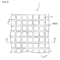
- Fig. 1 is a perspective view schematically showing one embodiment of a honeycomb structure-forming die of the present invention.
- Fig. 2 is an enlarged plan view showing a surface of the honeycomb structure-forming die shown in Fig. 1 .
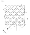
- Fig. 3 is an enlarged plan view showing a surface on the bonding face side of the first plate-shaped member constituting the honeycomb structure-forming die shown in Fig. 1 .
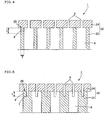
- Fig. 4 is a schematic cross-sectional view showing a cross section obtained by cutting the honeycomb structure-forming die shown in Fig. 2 along the A-A' line.
- Fig. 5 is a schematic cross-sectional view showing a cross section obtained by cutting the honeycomb structure-forming die shown in Fig. 2 along the B-B' line.
- Fig. 6 is a cross-sectional view illustrating a honeycomb structure-forming die.
- Fig. 7 is a cross-sectional view illustrating a honeycomb structure-forming die.
- Fig. 8 is a cross-sectional view illustrating a honeycomb structure-forming die.
- Fig. 9 is a schematic cross-sectional view showing a cross section of another embodiment of a honeycomb structure-forming die of the present invention, the cross-section being similar to that of Fig. 5 .
- Fig. 10 is an enlarged plan view showing a surface on the bonding face side of the first plate-shaped member constituting another embodiment of a honeycomb structure-forming die of the present invention.
- Fig. 11 is a perspective view schematically showing a honeycomb structure extrusion-formed with a die shown in Fig. 1 .
- Fig. 12 is a schematic cross-sectional view showing a cross section of another embodiment of a honeycomb structure-forming die of the present invention, the cross-section being similar to that of Fig. 5 .
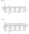
- Fig. 13 is an explanatory view showing the step (1) in an embodiment of a method for manufacturing a honeycomb structure-forming die of the present invention and shows a cross-section similar to that of Fig. 5 .
- Fig. 14 is an explanatory view showing the step (2) in an embodiment of a method for manufacturing a honeycomb structure-forming die of the present invention and shows a cross-section similar to that of Fig. 5 .
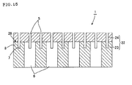
- Fig. 15 is an explanatory view showing the step (3) in an embodiment of a method for manufacturing a honeycomb structure-forming die of the present invention and shows a cross-section similar to that of Fig. 5 .
- Reference Numerals
- 1, 1a, 1b, 1c honeycomb structure-forming die (die), 5: slit, 6: back hole, 7: groove portion, 8: columnar portion, 12: honeycomb structure, 13:
- a honeycomb structure-forming die hereinbelow sometimes referred to simply as a "die”
- a manufacturing method thereof of the present invention will be described in detail.
- the present invention is by no means limited to these embodiments, and various changes, modifications, and improvements may be made on the basis of knowledge of a person of ordinary skill as long as they do not deviate from the scope of the present invention.
- a honeycomb structure-forming die 1 of the present embodiment is a die provided with a die substrate 22 having the first plate-shaped member 23 having back holes 6 for introducing a raw forming material and the second plate-shaped member 24 having slits 5 for forming the raw forming material into a lattice shape.
- first plate-shaped member 23 slit-shaped grooves 7 each corresponding with the shape of the slits 5 are formed on the bonding face side where the first plate-shaped member 23 is bonded with the second plate-shaped member 24.
- the first plate-shaped member 23 has a plurality of columnar portions 3 where at least a part is zoned by the groove portion 7.
- the groove portions 7 are formed in such a manner that the back holes 6 locate at the intersections of the groove portions 7.
- the columnar portions 8 are constituted in such a manner that the ratio (L/T) of the height L of the columnar portion 8 to the minimum width T in the end face on the bonding face 28 side of the first plate-shaped member 23 is within the range from 1/3 to 3.5.
- two plate-shaped members 23 and 24 constituting the die substrate 22 are hardly peeled from each other, and slits 5 can be processed well to the die substrate 22.
- surplus bonding material specifically, brazing material used for bonding the plate-shaped members 23 and 24 together can be evaporated and removed by heating upon bonding through the groove portions 7, thereby inhibiting the bonding material from remaining in the back holes 6 or the like.
- the first plate-shaped member 23 and the second plate-shaped member 24 are bonded together by bonding the tips of the columnar portions 8 and a surface of the second plate-shaped member 24, and portions corresponding with the groove portions 7 and the back holes 6 on the surface of the first plate-shaped member 23 are not actually bonded.
- a shearing load P1 in parallel with the bonding interface 28a and a peeling load P2 perpendicular to the bonding interface 28a are generated.
- the structure can withstand more under a shearing load P1 than under a peeling load P2. Therefore, by determining the ratio (L/T) of the minimum width of the columnar portions where the shearing load P1 acts to the height L of the columnar portions where the peeling load P2 acts in an optimum range, a balance between the peeling load and the shearing load in the bonding interface 28a is achieved so that the structure can withstand the loads, where the two plate-shaped members 23 and 24 constituting the die substrate 22 can hardly be peeled from each other and damaged.
- the optimum ratio (L/T) is within the range from 1/3 to 3.5 as described above.
- the ratio (L/T) is within the range of preferably 0.5 to 3, more preferably 0.9 to 2.5. Such a constitution can provide a die excellent in both the effect in inhibiting the plate-shaped members from being peeled from each other and the effect in removing the bonding material.
- the "minimum width T" of the columnar portions means the minimum length among the line segments passing through the centers of the end faces of the columnar portions and bisecting the area of each end face in the bonding face side of the first plate-shaped member.
- the "height L” of the columnar portions mean the length from the end face of the columnar portions to the bottom face of the groove portions.
- Fig. 9 is a schematic cross-sectional view showing a cross section of another embodiment of a honeycomb structure-forming die of the present invention, the cross-section being similar to that of Fig. 5 .
- the columnar portions 8 are zoned by the outer peripheral edges of the groove portions 6 and the grooves 7.
- the inner diameter of the back holes 6 or the pitch (i.e., distance between adjacent grooves) of the lattice-shaped groove portions 7 the position of the portion having the minimum width T of the columnar portions 8 may be changed.
- Fig. 10 is an enlarged plan view showing a surface on the bonding face side of the first plate-shaped member constituting another embodiment of a honeycomb structure-forming die of the present invention.
- the inner diameter of the back holes is often made large in order to increase the amount of the raw forming material introduced therein and to improve formability.
- the shape as shown in Fig. 3 is preferable. That is, it is preferable that the value (Q-2r) obtained by deducting the radii r of the closest two back holes 6 from the distance Q between the centers of the two back holes 6 is smaller than the distance S between adjacent parallel grooves, where the value (Q-2r) serves as the minimum width T of the columnar portions 8.
- Such a constitution can make the two plate-shaped members 23 and 24 constituting the die substrate 22 hardly peeled from each other and provide a die 1 excellent in formability.
- the honeycomb structure-forming die of the present embodiment is a die for extrusion-forming, as shown in, for example, Fig. 11 , a honeycomb structure 12 having porous partition walls 13 and a plurality of cells 14 functioning as fluid passages and separated and formed by the partition walls 13.
- the honeycomb structure 12 shown in Fig. 11 can suitably be used as a catalyst carrier using a catalytic function, such as an internal combustion engine, a boiler, a chemical reactor, and a fuel cell reformer; a filter for trapping particulate matter in exhaust gas (particulate matter-trapping filter); or the like.
- This slits 5 of the honeycomb structure-forming die 1 shown in Figs. 1 to 5 are for forming the portions of the partition walls 13 of the honeycomb structure 12 shown in Fig. 11 and are formed in a lattice shape as shown in Fig. 1 so as to correspond with the shape of the partition walls 13.
- Figs. 1 to 5 show an example where the slits 5, back holes 5, and groove portions 7 are formed in the approximate square region in the central portions of the plate-shaped members 23 and 24 having a disc shape.
- the region where the slits and the like are formed is not limited to the above region, and slits and the like may be formed, for example, in a circular region in the central portions of each of the plate-shapedmembers as shown in Fig. 11 , for example, as long as the die functions as a die for extrusion-forming the honeycomb structure 12.
- the back holes 6 of the honeycomb structure-forming die 1 are through-holes for introducing a raw forming material.
- the back holes 6 are formed in positions where slits 5 cross each other. Such a constitution enables the raw forming material to spread uniformly over the whole slits 5 upon extrusion-forming using the honeycomb structure-forming die 1 of the present embodiment to be able to realize high formability.
- the back holes 6 are formed at every other intersection of the slits 5 (or groove portions 7).
- the size or the like of the diameter of the openings of the back holes 6 can suitably be determined according to the size of the honeycomb structure-forming die 1, the shape of a honeycomb structure 12 (see Fig. 11 ) to be extrusion-formed, or the like.
- the size of the diameter of the openings of the back holes 6 is preferably 10 to 0.1 mm, more preferably 3 to 0.5 mm.
- Such back holes 6 can be formed by a conventionally known method such as electrochemical machining (ECM), electro-discharge machining (EDM), laser processing, mechanical processing by a drill or the like, etc.
- the groove portions 7 formed on the bonding face 28 side of the first plate-shaped member 23 function as buffer portions for introducing the raw forming material introduced from the back holes 6 into the slits 5, the raw forming material introduced from the back holes 6 can be moved smoothly without trouble upon extrusion-forming of the honeycomb structure, and the honeycomb structure can be formed with high accuracy.
- the groove portions 7 in the first plate-shaped member 23 and the slits 5 in the second plate-shaped member 24 have about the same width.
- the width of the groove portions 7 of the first plate-shaped member 23 may be larger than the width of the slits 5 of the second plate-shaped member 24.
- Fig. 12 is a schematic cross-sectional view showing a cross section of another embodiment of a honeycomb structure-forming die of the present invention, the cross-section being similar to that of Fig. 5 .
- the first plate-shaped member 23 is constituted of a metal or an alloy capable of causing at least one phase transformation selected from the group consisting of martensitic transformation, bainitic transformation, and pearlitic transformation by cooling an austenite phase though it is not particularly limited.
- Examples of such a metal or an alloy constituting the first plate-shaped member 23 include a metal or an alloy containing at least one metal selected from the group consisting of iron (Fe), titanium (Ti), nickel (Ni), copper (Cu), and aluminum (Al).
- the metal or alloy constituting the first plate-shaped member 23 may further include an additive such as carbon (C), silicon (Si), chromium (Cr), manganese (Mn), molybudenum (Mo), platinum (Pt), and palladium (Pd).
- Suitable examples of the alloy constituting the first plate-shaped member 23 include stainless alloy, for example, SUS630 (C: 0.07 or less, Si: 1.00 or less, Mn: 1.00 or less, P: 0.040 or less, S: 0.030 or less, Ni: 3.00 to 5.00, Cr: 15.50 to 17.50, Cu: 3.00 to 5.00, Nb+Ta: 0.15 to 0.45, Fe: balance (unit is mass%)).
- SUS630 C: 0.07 or less, Si: 1.00 or less, Mn: 1.00 or less, P: 0.040 or less, S: 0.030 or less, Ni: 3.00 to 5.00, Cr: 15.50 to 17.50, Cu: 3.00 to 5.00, Nb+Ta: 0.15 to 0.45, Fe: balance (unit is mass%)).
- Such stainless alloys make mechanical processing for forming the back holes 6 relatively easy and are inexpensive materials.
- the second plate-shaped member 24 is constituted of a tungsten based carbide alloy.
- the tungsten based carbide alloy is an alloy containing at least tungsten carbide and preferably an alloy obtained by sintering tungsten carbide by at least one metal selected from the group consisting of iron (Fe), cobalt (Co), nickel (Ni), titanium (Ti) and chromium (Cr).
- the tungsten based carbide alloy thus using at least a metal selected from the aforementioned group as a bonding material is particularly excellent in abrasion resistance and mechanical strength.
- a tungsten based carbide alloy include a tungsten based carbide alloy using cobalt (Co) as the bonding material.
- a specific example is a tungsten based carbide alloy containing 0.1 to 50 mass% of cobalt.
- the thickness of the first plate-shaped member 23 and the second plate-shaped member 24 can suitably be determined in consideration of, for example, general shapes of the slits 5 and the back holes 6.
- the ratio of the thickness of the first plate-shaped member 23 to the thickness of the second plate-shaped member 24 is preferably 0.1 to 200, more preferably 1 to 10.
- the honeycomb structure-forming die 1 of the present embodiment it is preferable to dispose a bonding material (brazing material) between the first plate-shaped member 23 and the second plate-shaped member 24 to bond them together.
- a conventionally known brazing material used when two different kinds of metals or alloys are bonded can be used.
- a surplus bonding material sometimes remains inside the back holes to deteriorate formability of the die.
- the surplus bonding material since it is possible to evaporate the surplus bonding material by heating upon bonding and discharge it outside through the groove portions formed in the first plate-shaped member, the surplus bonding material does not remain inside the back holes or the like.
- Suitable examples of the bonding material include a brazing material of a metal or an alloy containing at least one selected from the group consisting of copper (Cu), silver (Ag), gold (Au), nickel (Ni), and aluminum (Al).
- copper (Cu) or an alloy containing copper (Cu) can particularly suitably be used because of high permeability in a stainless steel suitably usable as the first plate-shaped member.
- Such a bonding material may further contain an additive such as palladium (Pd), silicon (Si), tin (Sn), cobalt (Co), phosphorous (P), manganese (Mn), zinc (Zn), and boron (B).
- an additive such as palladium (Pd), silicon (Si), tin (Sn), cobalt (Co), phosphorous (P), manganese (Mn), zinc (Zn), and boron (B).
- Pd palladium
- Si silicon
- Sn tin
- Co cobalt
- P phosphorous
- Mn manganese
- Zn zinc
- B boron
- lattice-shaped groove portions 7 are formed on a surface (on the bonding face 28 side in Fig. 1 ) of the first plate-shaped member 23 of a metal or an alloy (step (1)).
- the groove portions 7 are formed on a surface 28 side of the first plate-shaped member 23 in such a manner that the ratio (L/T) of the height L of the columnar portions 8 of a honeycomb structure-forming die 1 obtained as the final product as shown in, for example, Figs. 1 to 5 to the minimum width T of the columnar portions 8 is within the range from 1/3 to 3.5.
- the aforementioned ratio (L/T) is within the range of preferably 0.5 to 3, more preferably 0.9 to 2.5.
- the first plate-shaped member 23 constitutes a portion where mainly back holes 6 in the die substrate 22 (see Fig. 1 ) are formed.
- the first plate-shaped member 23 there can be used a member constituted of a metal or an alloy used for a conventionally know honeycomb structure-forming die.
- the metals and alloys described above as suitable examples in the embodiment of a honeycomb structure-forming die may be used.
- a method for forming the groove 7 there may suitably be used a conventionally known method such as grinding by a diamond grinding stone or electro-discharge machining.
- the back holes 6 communicating with the groove portions 7 from the other surface of the first plate-shaped member 23 maybe formed.
- the back holes 6 since the columnar portions 8 are zoned by the back holes 6 and the groove portions 7, it is preferable to form the back holes 6 together with the groove portions 7 in the step (1).
- ECM electrochemical machining
- EDM electro-discharge machining
- laser processing or mechanical processing by a drill or the like
- mechanical processing by a drill or the like may suitably be employed.
- the back holes may be through-holes passing through the first plate-shaped member 23 to the surface 28 side on one side of the first plate-shaped member 23 as shown in Fig. 13 or blind holes as the die 1a shown in Fig. 9 .
- the back holes in a later step for example, the step (3) or the like after a die substrate is manufactured without forming the back holes in the aforementioned step (1).
- the groove portions in consideration of the positions of the back holes formed in the first plate-shaped member, the inner diameter of the back holes, and the like.
- the groove portions are formed in consideration of the shape after the back holes are formed.
- the second plate-shaped member 24 of a metal or an alloy is laminated on the surface 28 on one side of the first plate-shaped member 23 having the groove portions 7 formed therein, and the first plate-shaped member 23 and the second plate-shaped member 24 are bonded together to obtain the die substrate 22 (step (2)).
- the second plate-shaped member 24 constitutes mainly the portions where the slits 5 (see Fig. 1 ) are formed in the die substrate 22 (see Fig. 1 ) and can suitably be used a member constituted of, for example, tungsten based carbide alloy.
- a carbide alloy there can be used the carbide alloy described above as a suitable example in the embodiment of a honeycomb structure-forming die of the present invention.
- the plate-shaped members 23 and 24 may be bonded by disposing a bonding material between the first plate-shaped member 23 and the second plate-shaped member 24 when the second plate-shaped member 24 is laminated on the surface 28 of the first plate-shaped member 23.
- a bonding material there may suitably be employed the brazing material described in the aforementioned embodiment of a honeycomb structure-forming die of the present invention.
- first plate-shaped member 23 and the second plate-shaped member 24 are bonded into a laminate, it is preferable to bond them together by heating the plate-shaped members 23 and 24 at a temperature not lower than the temperature where the first plate-shaped member 23 causes austenite transformation. Such a constitution enables the first plate-shaped member 23 and the second plate-shaped member 24 to be well bonded together.
- the metal texture or the alloy texture constituting the first plate-shaped member 23 may be subjected to phase transformation by decreasing the temperature of the die substrate 22 obtained above to the temperature where at least one of the aforementioned phase transformation starts.
- the dimensions of the first plate-shaped member 23 can be changed to reduce residual stress in the bonding face 28 between the first plate-shaped member 23 and the second plate-shaped member 24.
- temperature of the first plate-shaped member 23 and the second plate-shaped member 24 bonded above is decreased to the temperature where the aforementioned at least one phase transformation starts at a temperature falling rate of 0.1 to 100°C/min.
- the slits 5 corresponding with the shape of the aforementioned groove portions 7 are formed from the surface opposite to the bonding face 28 with the first plate-shaped member 23 of the second plate-shaped member 24 to obtain a honeycomb structure-forming die 1 (step (3)).
- the method for forming the slits 5 there is no particular limitation on the method for forming the slits 5, and a conventionally known method such as grinding with a diamond grinding stone or electro-discharge machining (EDM) may suitably be employed.
- EDM electro-discharge machining
- the slits 5 have a square lattice shape.
- the shape of the slits 5 formed in the second plate-shaped member 24 is not limited to a square lattice shape and may be another polygonal lattice shape.
- the width of the slits 5 formed in the second plate-shaped member 24 can suitably be determined according to the shape of a honeycomb structure 12 (see Fig. 11 ) to be formed.
- the width of the slits 5 is preferably 5 to 5000 ⁇ m, more preferably 10 to 500 ⁇ m.
- honeycomb structure-forming die 1 where the back holes 6 for introducing a raw forming material and the slits 5 for forming the raw forming material into a lattice shape as shown in Figs. 1 to 5 .
- Example 1 There was manufactured a honeycomb structure-forming die having back holes for introducing a raw forming material and slits for forming the raw forming material into a lattice shape and being capable of forming a honeycomb structure by extruding from a slit the raw forming material introduced from the back holes.
- Example 1 a die substrate was obtained by bonding the first plate-shaped member constituted of SUS630 (C: 0.07 or less, Si: 1.00 or less, Mn: 1.00 or less, P: 0.040 or less, S: 0.030 or less, Ni: 3.00 to 5.00, Cr: 15.50 to 17.50, Cu: 3.00 to 5.00, Nb+Ta: 0. 15 to 0. 45, Fe: balance (unit is mass%)) and the second plate-shaped member constituted of a tungsten based carbide alloy containing 16 mass% of cobalt together, and a honeycomb structure-forming die was manufactured by using the die substrate.
- SUS630 C: 0.07 or less, Si: 1.00 or less, Mn: 1.00 or less, P: 0.040 or less, S: 0.030 or less, Ni: 3.00 to 5.00, Cr: 15.50 to 17.50, Cu: 3.00 to 5.00, Nb+Ta: 0. 15 to 0. 45, Fe: balance (unit is mass%)
- the second plate-shaped member constituted of
- the first plate-shaped member has a disc shape having a diameter of 215 mm and a thickness of 20 mm.
- the second plate-shaped member has a disc shape having a diameter of 210 mm and thickness of 2.5 mm.
- the lattice-shaped groove portions having a depth of 1.5 mm and the back holes having an opening diameter of 1.4 mm were formed by electrochemical machining (ECM).
- the groove portions had a width of 0.3 mm and a pitch of 1.37 mm.
- the minimum width T of the columnar portions in the end face on the bonding face side was 0.53 mm with the height L of the columnar portions being 1.5 mm, and the ratio (L/T) of the height L to the minimum width T was 2.82.
- first plate-shaped member and the second plate-shaped member were put into a laminate by disposing a brazing material between them, they were heated at 1120°C to bond the first plate-shaped member and the second plate-shaped member together to obtain a die substrate.
- the die substrate thus obtained was evaluated for peeling at the bonding faces of the first plate-shaped member and the second plate-shaped member.
- the evaluation results are shown in Table 1.
- the peeling at the bonding faces was confirmed in ultrasonic crack detection with an ultrasonic crack detection imaging device. Incidentally, “good” was given for the cases where no peeling was found at the bonding faces, and “bad” was given for the cases where peeling was found at the bonding faces.
- slits were formed in the second plate-shaped member to obtain a honeycomb structure-forming die.
- the slits were formed into a square lattice shape with a diamond grinding stone.
- the slits had a width of 0.1 mm and a pitch of 1.37 mm.
- the honeycomb structure-forming die in Examples 2 to 15 were manufactured in the same manner as in Example 1 except that the diameter of the openings of the back holes, the depth of the groove portions, and the pitch of the groove portions were changed as shown in Tables 1 and 2.
- the diameter of the openings of the back holes, the depth of the groove portions, the pitch of the groove portions, the minimum width T of the columnar portions, the height L of the columnar portions, and the ratio (L/T) of each die are shown in Tables 1 and 2.
- honeycomb structure-forming dies of Examples 2 to 15 were evaluated for peeling at the bonding faces of the first plate-shaped member and the second plate-shaped member in the same manner as in Example 1. The evaluation results are shown in Tables 1 and 2.
- the groove portions shown in Table 3 were formed using the same first and second plate-shaped members as in Example 1 to manufacture a honeycomb structure-forming die.
- the back holes in the first plate-shaped member were blind holes as shown in Fig. 9 , and the groove portions which reach the blind holes were formed.
- the distance between adjacent parallel groove portions i. e. , value obtained by deducting the groove width from the pitch of the groove portions serves as the minimum width of the columnar portions.
- honeycomb structure-forming dies of the Examples 16 to 19 were evaluated for peeling at the bonding faces of the first plate-shaped member and the second plate-shaped member in the same manner as in Example 1. The evaluation results are shown in Table 3.
- the honeycomb structure-forming die in Comparative Examples 1 to 6 were manufactured in the same manner as in Example 1 except that the diameter of the openings of the back holes, the depth of the groove portions, and the pitch of the groove portions were changed as shown in Table 1.
- the diameter of the openings of the back holes, the depth of the groove portions, the pitch of the groove portions, the minimum width T of the columnar portions, the height L of the columnar portions, and the ratio (L/T) of each die are shown in Table 4.
- the honeycomb structure-forming dies of Comparative Examples 1 to 6 were evaluated for peeling at the bonding faces of the first plate-shaped member and the second plate-shaped member in the same manner as in Example 1. The evaluation results are shown in Table 4.
- honeycomb structure-forming dies of the Examples 1 to 19 peeling was not confirmed, and two plate-shaped members were firmly bonded together.
- the bonding strength at the aforementioned bonding faces was strong enough to withstand the pressure upon extrusion-forming of a honeycomb structure, and peeling was not caused at the bonding faces of the two plate-shaped members constituting the die substrate even when the total extrusion distance reached 10,000 m or more.
- honeycomb structure-forming dies were excellent in formability, honeycomb structures (honeycomb formed articles) could be well formed.
- each of the honeycomb structure-forming dies of the Comparative Examples 1 to 6 peeling was confirmed at the bonding faces in the evaluation on peeling at the bonding faces of the die substrate. Therefore, there were the cases that the two plate-shaped members constituting the die substrate peeled from each other at the time of forming the slits in the die substrate and that the two plate-shaped members constituting the die substrate peeled from each other due to the pressure upon extrusion-forming a honeycomb structure even in the case that they did not peel from each other at the time of forming the slits.
- a honeycomb structure-forming die of the present invention can be used upon forming a catalyst carrier using a catalytic function, such as an internal combustion engine, a boiler, a chemical reactor, and a fuel cell reformer; a filter for trapping particulate matter in exhaust gas.
- a manufacturing method for a honeycomb structure-forming die of the present invention enables to simply manufacture the aforementioned honeycomb structure-forming die.
Landscapes
- Engineering & Computer Science (AREA)
- Mechanical Engineering (AREA)
- Manufacturing & Machinery (AREA)
- Chemical & Material Sciences (AREA)
- Ceramic Engineering (AREA)
- Composite Materials (AREA)
- Materials Engineering (AREA)
- Press-Shaping Or Shaping Using Conveyers (AREA)
Applications Claiming Priority (1)
| Application Number | Priority Date | Filing Date | Title |
|---|---|---|---|
| JP2008067870A JP5361224B2 (ja) | 2008-03-17 | 2008-03-17 | ハニカム構造体成形用口金、及びその製造方法 |
Publications (3)
| Publication Number | Publication Date |
|---|---|
| EP2105272A2 true EP2105272A2 (fr) | 2009-09-30 |
| EP2105272A3 EP2105272A3 (fr) | 2012-03-07 |
| EP2105272B1 EP2105272B1 (fr) | 2016-07-06 |
Family
ID=40943579
Family Applications (1)
| Application Number | Title | Priority Date | Filing Date |
|---|---|---|---|
| EP09250690.6A Active EP2105272B1 (fr) | 2008-03-17 | 2009-03-12 | Filière pour formation de structure en nid d'abeille et son procédé de fabrication |
Country Status (4)
| Country | Link |
|---|---|
| US (1) | US8235699B2 (fr) |
| EP (1) | EP2105272B1 (fr) |
| JP (1) | JP5361224B2 (fr) |
| CN (1) | CN101537658B (fr) |
Families Citing this family (11)
| Publication number | Priority date | Publication date | Assignee | Title |
|---|---|---|---|---|
| JP5345487B2 (ja) | 2008-09-24 | 2013-11-20 | 日本碍子株式会社 | 接合体及びハニカム構造体成形用口金 |
| JP5379460B2 (ja) * | 2008-12-05 | 2013-12-25 | 日本碍子株式会社 | ハニカム構造体成形用口金及びハニカム構造体成形用口金の製造方法 |
| JP5313851B2 (ja) * | 2009-12-09 | 2013-10-09 | 日本碍子株式会社 | ハニカム構造体成形用口金 |
| CN103429375B (zh) * | 2011-03-25 | 2016-10-26 | 日本碍子株式会社 | 碳化钨基硬质合金接合体及其制造方法 |
| CN104379310B (zh) * | 2012-06-04 | 2016-11-09 | 日本碍子株式会社 | 蜂窝结构体成形用模头及其制造方法 |
| MX357751B (es) * | 2012-06-04 | 2018-07-23 | Ngk Insulators Ltd | Matriz para formar estructura de panal y metodo para su fabricacion. |
| US20130337283A1 (en) * | 2012-06-14 | 2013-12-19 | Kennametal lndia Limited | Process For Joining Carbide And Non Carbide Materials And The Method Thereof |
| US10994378B2 (en) * | 2014-10-27 | 2021-05-04 | Corning Incorporated | Die body apparatus and methods |
| WO2017087758A1 (fr) * | 2015-11-20 | 2017-05-26 | Corning Incorporated | Filières d'extrusion pour corps en nid-d'abeilles |
| CN108081439B (zh) * | 2018-01-10 | 2019-12-13 | 李根芝 | 一种空心砖砖胚制备装置 |
| CN111997530B (zh) * | 2020-09-15 | 2024-06-25 | 广东钜鑫新材料科技股份有限公司 | 人造金刚石硬质合金复合片 |
Citations (4)
| Publication number | Priority date | Publication date | Assignee | Title |
|---|---|---|---|---|
| JP2000326318A (ja) | 1999-03-18 | 2000-11-28 | Denso Corp | ハニカム構造体成形用金型及びその製造方法 |
| JP2003285308A (ja) | 2002-03-28 | 2003-10-07 | Ngk Insulators Ltd | ハニカム成形用口金及びこれを用いたハニカム成形用口金治具 |
| JP2006051682A (ja) | 2004-08-11 | 2006-02-23 | Ngk Insulators Ltd | ハニカム構造体成形用口金及びその製造方法 |
| JP2007181976A (ja) | 2006-01-06 | 2007-07-19 | Ngk Insulators Ltd | ハニカム構造体成形用口金の製造方法 |
Family Cites Families (8)
| Publication number | Priority date | Publication date | Assignee | Title |
|---|---|---|---|---|
| JPS6099443A (ja) * | 1983-11-02 | 1985-06-03 | Ngk Insulators Ltd | ハニカム成型用ダイスおよびその製造方法 |
| JPS6347103A (ja) * | 1986-08-14 | 1988-02-27 | 日本碍子株式会社 | ハニカム成型用ダイスおよびその製造方法 |
| JP2925921B2 (ja) | 1994-03-14 | 1999-07-28 | 日本碍子株式会社 | セラミックス構造体押出用口金 |
| JPH09300326A (ja) * | 1996-05-16 | 1997-11-25 | Denso Corp | ハニカム成形用ダイス及びその製造方法 |
| JP2003285309A (ja) * | 2002-03-28 | 2003-10-07 | Ngk Insulators Ltd | ハニカム成形用口金 |
| JP2008522873A (ja) * | 2004-12-09 | 2008-07-03 | コーニング インコーポレイテッド | ハニカム押出ダイの製造 |
| WO2007114089A1 (fr) * | 2006-03-31 | 2007-10-11 | Ngk Insulators, Ltd. | Matrice pour former une structure en nid d'abeilles et procede de fabrication de cette matrice |
| JP2008023978A (ja) * | 2006-06-21 | 2008-02-07 | Hitachi Metals Ltd | 押出成形用口金 |
-
2008
- 2008-03-17 JP JP2008067870A patent/JP5361224B2/ja active Active
-
2009
- 2009-02-26 US US12/393,459 patent/US8235699B2/en active Active
- 2009-03-12 EP EP09250690.6A patent/EP2105272B1/fr active Active
- 2009-03-17 CN CN2009101288369A patent/CN101537658B/zh active Active
Patent Citations (4)
| Publication number | Priority date | Publication date | Assignee | Title |
|---|---|---|---|---|
| JP2000326318A (ja) | 1999-03-18 | 2000-11-28 | Denso Corp | ハニカム構造体成形用金型及びその製造方法 |
| JP2003285308A (ja) | 2002-03-28 | 2003-10-07 | Ngk Insulators Ltd | ハニカム成形用口金及びこれを用いたハニカム成形用口金治具 |
| JP2006051682A (ja) | 2004-08-11 | 2006-02-23 | Ngk Insulators Ltd | ハニカム構造体成形用口金及びその製造方法 |
| JP2007181976A (ja) | 2006-01-06 | 2007-07-19 | Ngk Insulators Ltd | ハニカム構造体成形用口金の製造方法 |
Also Published As
| Publication number | Publication date |
|---|---|
| JP2009220426A (ja) | 2009-10-01 |
| JP5361224B2 (ja) | 2013-12-04 |
| CN101537658A (zh) | 2009-09-23 |
| EP2105272A3 (fr) | 2012-03-07 |
| CN101537658B (zh) | 2013-01-09 |
| US8235699B2 (en) | 2012-08-07 |
| EP2105272B1 (fr) | 2016-07-06 |
| US20090232927A1 (en) | 2009-09-17 |
Similar Documents
| Publication | Publication Date | Title |
|---|---|---|
| EP2105272B1 (fr) | Filière pour formation de structure en nid d'abeille et son procédé de fabrication | |
| JP4426400B2 (ja) | ハニカム構造体成形用口金及びその製造方法 | |
| EP2002949B1 (fr) | Matrice pour former une structure en nid d'abeilles et procede de fabrication de cette matrice | |
| JP6046712B2 (ja) | ハニカム構造体成形用口金及びその製造方法 | |
| EP1500479B1 (fr) | Ferrule de formage de nids d'abeille et crible pour ferrule utilisant cette ferrule | |
| JP5897552B2 (ja) | 炭化タングステン基超硬合金接合体及びその製造方法 | |
| EP2857163A1 (fr) | Filière pour mouler une structure en nid d'abeilles et procédé de fabrication de cette filière | |
| US8353695B2 (en) | Die for forming honeycomb structure | |
| KR100602471B1 (ko) | 허니콤 성형용 다이 | |
| JP5185501B2 (ja) | ハニカム構造体成形用口金の製造方法 | |
| JP5513865B2 (ja) | 超硬合金接合体及びその製造方法 | |
| JP4754372B2 (ja) | 異種材料接合体の製造方法 | |
| JP5162268B2 (ja) | ハニカム構造体成形用口金 |
Legal Events
| Date | Code | Title | Description |
|---|---|---|---|
| PUAI | Public reference made under article 153(3) epc to a published international application that has entered the european phase |
Free format text: ORIGINAL CODE: 0009012 |
|
| AK | Designated contracting states |
Kind code of ref document: A2 Designated state(s): AT BE BG CH CY CZ DE DK EE ES FI FR GB GR HR HU IE IS IT LI LT LU LV MC MK MT NL NO PL PT RO SE SI SK TR |
|
| AX | Request for extension of the european patent |
Extension state: AL BA RS |
|
| PUAL | Search report despatched |
Free format text: ORIGINAL CODE: 0009013 |
|
| AK | Designated contracting states |
Kind code of ref document: A3 Designated state(s): AT BE BG CH CY CZ DE DK EE ES FI FR GB GR HR HU IE IS IT LI LT LU LV MC MK MT NL NO PL PT RO SE SI SK TR |
|
| AX | Request for extension of the european patent |
Extension state: AL BA RS |
|
| RIC1 | Information provided on ipc code assigned before grant |
Ipc: B28B 3/26 20060101AFI20120130BHEP Ipc: B29C 47/20 20060101ALI20120130BHEP Ipc: B28B 7/34 20060101ALI20120130BHEP Ipc: B22F 3/11 20060101ALI20120130BHEP Ipc: B23P 15/24 20060101ALI20120130BHEP |
|
| 17P | Request for examination filed |
Effective date: 20120808 |
|
| AKX | Designation fees paid |
Designated state(s): DE FR |
|
| 17Q | First examination report despatched |
Effective date: 20150323 |
|
| GRAP | Despatch of communication of intention to grant a patent |
Free format text: ORIGINAL CODE: EPIDOSNIGR1 |
|
| RIC1 | Information provided on ipc code assigned before grant |
Ipc: B28B 3/26 20060101AFI20151022BHEP Ipc: B29C 47/20 20060101ALI20151022BHEP Ipc: B28B 7/34 20060101ALI20151022BHEP Ipc: B22F 7/00 20060101ALI20151022BHEP Ipc: B22F 3/11 20060101ALI20151022BHEP Ipc: B23P 15/24 20060101ALI20151022BHEP Ipc: B29C 47/00 20060101ALI20151022BHEP Ipc: B22F 5/00 20060101ALI20151022BHEP Ipc: B29L 31/60 20060101ALI20151022BHEP |
|
| INTG | Intention to grant announced |
Effective date: 20151119 |
|
| GRAP | Despatch of communication of intention to grant a patent |
Free format text: ORIGINAL CODE: EPIDOSNIGR1 |
|
| GRAJ | Information related to disapproval of communication of intention to grant by the applicant or resumption of examination proceedings by the epo deleted |
Free format text: ORIGINAL CODE: EPIDOSDIGR1 |
|
| GRAP | Despatch of communication of intention to grant a patent |
Free format text: ORIGINAL CODE: EPIDOSNIGR1 |
|
| GRAS | Grant fee paid |
Free format text: ORIGINAL CODE: EPIDOSNIGR3 |
|
| INTG | Intention to grant announced |
Effective date: 20160504 |
|
| GRAA | (expected) grant |
Free format text: ORIGINAL CODE: 0009210 |
|
| INTG | Intention to grant announced |
Effective date: 20160504 |
|
| INTG | Intention to grant announced |
Effective date: 20160519 |
|
| AK | Designated contracting states |
Kind code of ref document: B1 Designated state(s): DE FR |
|
| REG | Reference to a national code |
Ref country code: DE Ref legal event code: R096 Ref document number: 602009039560 Country of ref document: DE |
|
| REG | Reference to a national code |
Ref country code: FR Ref legal event code: PLFP Year of fee payment: 9 |
|
| REG | Reference to a national code |
Ref country code: DE Ref legal event code: R097 Ref document number: 602009039560 Country of ref document: DE |
|
| PLBE | No opposition filed within time limit |
Free format text: ORIGINAL CODE: 0009261 |
|
| STAA | Information on the status of an ep patent application or granted ep patent |
Free format text: STATUS: NO OPPOSITION FILED WITHIN TIME LIMIT |
|
| 26N | No opposition filed |
Effective date: 20170407 |
|
| REG | Reference to a national code |
Ref country code: FR Ref legal event code: PLFP Year of fee payment: 10 |
|
| PGFP | Annual fee paid to national office [announced via postgrant information from national office to epo] |
Ref country code: FR Payment date: 20210210 Year of fee payment: 13 |
|
| PG25 | Lapsed in a contracting state [announced via postgrant information from national office to epo] |
Ref country code: FR Free format text: LAPSE BECAUSE OF NON-PAYMENT OF DUE FEES Effective date: 20220331 |
|
| PGFP | Annual fee paid to national office [announced via postgrant information from national office to epo] |
Ref country code: DE Payment date: 20260128 Year of fee payment: 18 |