EP2105396A2 - Blattzuführungsvorrichtung - Google Patents
Blattzuführungsvorrichtung Download PDFInfo
- Publication number
- EP2105396A2 EP2105396A2 EP09155366A EP09155366A EP2105396A2 EP 2105396 A2 EP2105396 A2 EP 2105396A2 EP 09155366 A EP09155366 A EP 09155366A EP 09155366 A EP09155366 A EP 09155366A EP 2105396 A2 EP2105396 A2 EP 2105396A2
- Authority
- EP
- European Patent Office
- Prior art keywords
- sheet
- point
- conveyance
- guide surface
- guide member
- Prior art date
- Legal status (The legal status is an assumption and is not a legal conclusion. Google has not performed a legal analysis and makes no representation as to the accuracy of the status listed.)
- Granted
Links
Images





Classifications
-
- B—PERFORMING OPERATIONS; TRANSPORTING
- B65—CONVEYING; PACKING; STORING; HANDLING THIN OR FILAMENTARY MATERIAL
- B65H—HANDLING THIN OR FILAMENTARY MATERIAL, e.g. SHEETS, WEBS, CABLES
- B65H3/00—Separating articles from piles
- B65H3/46—Supplementary devices or measures to assist separation or prevent double feed
- B65H3/52—Friction retainers acting on under or rear side of article being separated
- B65H3/5246—Driven retainers, i.e. the motion thereof being provided by a dedicated drive
- B65H3/5253—Driven retainers, i.e. the motion thereof being provided by a dedicated drive the retainers positioned under articles separated from the top of the pile
- B65H3/5261—Retainers of the roller type, e.g. rollers
-
- B—PERFORMING OPERATIONS; TRANSPORTING
- B65—CONVEYING; PACKING; STORING; HANDLING THIN OR FILAMENTARY MATERIAL
- B65H—HANDLING THIN OR FILAMENTARY MATERIAL, e.g. SHEETS, WEBS, CABLES
- B65H3/00—Separating articles from piles
- B65H3/66—Article guides or smoothers, e.g. movable in operation
- B65H3/68—Article guides or smoothers, e.g. movable in operation immovable in operation
-
- B—PERFORMING OPERATIONS; TRANSPORTING
- B65—CONVEYING; PACKING; STORING; HANDLING THIN OR FILAMENTARY MATERIAL
- B65H—HANDLING THIN OR FILAMENTARY MATERIAL, e.g. SHEETS, WEBS, CABLES
- B65H2301/00—Handling processes for sheets or webs
- B65H2301/50—Auxiliary process performed during handling process
- B65H2301/51—Modifying a characteristic of handled material
- B65H2301/512—Changing form of handled material
- B65H2301/5125—Restoring form
- B65H2301/51256—Removing waviness or curl, smoothing
Definitions
- the present invention relates to a sheet feeding device that separates a sheet from a plurality of stacked sheets one sheet by one sheet and conveys to an image forming section or to an image reading section, in an image forming apparatus or an image reading apparatus.
- the sheet feeding device of this kind those each being composed of a pickup roller, a feed roller and a retarding roller as is disclosed in, for example, Unexamined Japanese Patent Application Publication No. 5-43073 , are widely used.
- a sheet located at the outermost position of stacked sheets is caused to receive conveyance force by a pickup roller to be fed out and is conveyed after being separated from others by a feed roller and a retarding roller.
- the sheet feeding device described in the Unexamined Japanese Patent Application Publication No. 5-43073 has a problem that conveyance of a thick sheet is not smooth, and sheet feeding failure tends to be caused.
- Fig. 1 (b) shows a phenomenon that takes place in the sheet feeding for curved sheet S shown in Fig. 1 (a) .
- leading edges K on both lifted end portions of the sheet S hit an inclined guide surface of the guide member 110, when Y represents the direction of conveyance for a sheet in sheet feeding.
- the sheet S that hits the guide surface does not bend along the guide surface because stiffness of the sheet S is high, and thus, a leading edge of the sheet S is blocked by the guide member 110, which stops conveyance of the sheet S.
- An objective of the invention is to solve the aforesaid problem in a conventional sheet feeding device, and thereby to provide a sheet feeding device that can feed sheets stably even in the case of a thick sheet.
- a sheet feeding device which includes a pickup device which feeds a sheet by rotating while the pickup device comes in contact with a sheet located at an outermost position of a loaded stack of sheets, and a separation device which separates the sheet fed by the pickup device from another sheet and conveys the sheet with the separation device having a conveying device for conveying the sheet in a conveyance direction and a removing device for providing conveyance resistance on a lower surface of the sheet with the sheet feeding device further including a guide member for guiding the sheet from a point upstream of the separation device to a point downstream of the separation device in the conveyance direction, wherein the guide member comprises a sloping guide surface which is a slope so as to form a conveyance gap which is wider on an upstream side and narrower on a downstream side in the conveyance direction and wherein the sloping guide surface is formed so that an uppermost stream point of the slope is positioned on an upstream side of a separation point which is formed by the conveying device and the removing device in the conveyance direction and a lowermost
- An image forming apparatus provided with the sheet feeding device of Item 1.
- FIG. 1 (a) and Fig. 1 (b) is a diagram illustrating no-feed that is caused in sheet feeding for curved thick sheets.
- Fig. 2 is a diagram showing overall composition of an image forming apparatus in which a sheet feeding device relating to the embodiment of the invention is incorporated.
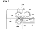
- Fig. 3 is a front sectional view of sheet feeding device 100 relating to the embodiment of the invention.
- Fig. 4 is a top view of sheet feeding device 100 shown in Fig. 3 .
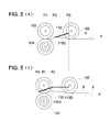
- Fig. 5 (a) and Fig. 5 (b) are diagrams illustrating positional relationships between a guide member and a separation device, respectively in the central portion and an end portion in the width direction of a sheet.
- FIG. 6 (a) and Fig. 6 (b) is a diagram showing a sheet feeding testing instrument.
- FIG. 7 (a) and Fig. 7 (b) is a diagram showing an amount of curve.
- Fig. 2 is a diagram showing overall composition of an image forming apparatus in which a sheet feeding device relating to the embodiment of the invention is incorporated.
- Image forming apparatus A is an apparatus for forming an image on sheet S through a well-known electrophotographic system, and the image forming apparatus A has thereon automatic document feeder DF. Further, the image forming apparatus A is equipped with image reading section 1, image processing section 2, image forming section 3, sheet storage section 4, sheet feeding section 100 and reversal and sheet-ejection device 6.
- the automatic document feeder DF is an apparatus that separates documents placed on a document table (having no symbol) into a single sheet one by one, then, conveys it to an image reading position, and ejects it to sheet ejection tray (having no symbol).
- This automatic document feeder DF is also constructed to be capable of reversing a document upside down after conveying it to an image reading position, then, conveying again to the image reading position, to be ejected on a sheet ejection tray, and thus, it is possible to cause image reading section 1 described later to read only one side or both sides of the document.
- the automatic document feeder DF is made up so that a document may travel on an image reading position, and so that image reading section 1 which will be described later may read an image on a traveling document.
- image reading section 1 which will be described later may read an image on a traveling document.
- the image reading section 1 is a device that reads an image on a document to obtain image data and it is a device that reads an image on a document that is conveyed by the automatic document feeder DF. Namely, a document conveyed by the automatic document feeder DF is converted into image signals, on a photoelectric basis, by CCD (image sensor) 1A representing an image pickup device, through an optical system (having no symbol) that is at a standstill. In addition, as stated above, it is also possible to constitute to obtain image data from a document that is at a standstill, while moving an optical system. Further, though image forming apparatus A is equipped with image reading section 1, in the present embodiment, the image forming apparatus may also be one that obtains image data from an outer equipment through a network and thereby forms an image based on the image data.
- Image processing section 2 conducts analog processing, A/D conversion, shading correction and image compression processing for analog signals converted by CCD image sensor 1A on a photoelectric basis. After image processing by the image processing section 2, signals are sent to image writing section 31 of image forming section 3 through a storing device (memory) AM that stores image data as occasion demands.
- a storing device memory
- the image forming section 3 is one that forms an image on sheet S, and it forms an image through an electrophotographic system.
- the image forming section 3 has therein image writing section 31, image forming unit 32 and fixing section 33.
- the image writing section 31 is a device that gives exposure to a photoconductor drum (having no symbol) of image forming unit 32 which will be described later, based on the image data which have been read by image reading section 1 and have been image-processed by image processing section 2, and forms a latent image of an image.
- light outputted from semiconductor laser (having no symbol) based on the image data is applied on a photoconductor drum of image forming unit 32, and a latent image is formed.
- the image forming unit 32 On the image forming unit 32, there are conducted charging, exposure and development for the photoconductor drum, and a toner image is formed on the photoconductor drum. The toner image is transferred onto sheet S conveyed toward the image forming unit 32. The photoconductor drum after transferring will be cleaned.
- the fixing section 33 is a device that fixes a toner image transferred onto sheet S by image forming unit 32.
- Sheet storing section 4 is a device to store sheets S on which an image will be formed by image forming section 3, and it has therein trays 41, 42 and 43 as well as manual bypass tray 44.
- Sheet feeding device 100 is a device that feeds out sheet S one by one from a plurality of trays 41 - 43, and feeds a sheet to image forming section 3. This sheet feeding device 100 is provided to correspond to each of trays 41 - 43 to feed sheets S placed in trays 41 - 43.
- Sheet S fed out of the sheet feeding device 100 is conveyed to registration roller 55 through conveyance section 5.
- Sheet S fed through the manual feeding tray 44 is supplied to the registration roller 55 by sheet feeding device 50.
- Reversal and sheet-ejection device 6 includes a sheet ejection device that ejects sheet S on which a toner image is fixed from image forming apparatus A, a reversing and ejecting device that reverses and ejects sheet S and a reversing device that reverses sheet S and conveys it again to image forming section 3.
- the reversal and sheet-ejection device 6 has therein sheet ejection roller 61 for ejecting a sheet from image forming apparatus A, sheet reversing section 62 that reverses sheet S upside down, switching section 63 that switches a path to convey sheet S coming out of fixing section 33 to the sheet ejection roller 61 side or to the reversing section 62 side and conveyance section 64 that conveys sheet S reversed at the sheet reversing section 62 to the image forming section 3 again. Then, when ejecting the sheet S on which a toner image is fixed as it is, the sheet S is guided to the sheet ejection roller 61 side by the switching section 63 to be ejected out of image forming apparatus A.
- the sheet S When ejecting the sheet S on which a toner image is fixed after reversing the sheet upside down, the sheet S is guided to the sheet reversing section 62 side by the switching section 63 to be conveyed temporarily, then, the advancing direction of the sheet is reversed, and the sheet is conveyed to the sheet ejection roller 61 side, to be ejected out of image forming apparatus A.
- the sheet S is guided to the reversing section 62 side to be conveyed, then, the advancing direction for the sheet is reversed, and the sheet is conveyed by conveyance section 64 toward the upstream side of registration roller 55 in the conveyance direction, thus, an image is formed on the opposite side.
- Fig. 3 is a front sectional view of sheet feeding device 100 relating to the embodiment of the invention
- Fig. 4 is a top view of sheet-feeding device 100 shown in Fig. 3
- Fig. 5 (a) and Fig. 5 (b) are diagrams illustrating positional relationships between a guide member and a separation device, respectively in a central portion and an end portion in the width direction of a sheet (direction perpendicular to conveyance direction for the sheet).
- the sheet-feeding device 100 has therein pickup roller 102 representing a pickup device, feed roller 103 representing a conveyance device that constitutes a separation device and retarding roller 104 representing a removing device that constitutes the aforesaid separation device.
- Feed roller 103 and retarding roller 104 are supported respectively on fixed shafts to be rotated.
- the pickup roller 102 is supported on swing lever 101 that is supported by a rotary shaft for the feed roller 103, and it is displaced vertically by swinging of the swing lever 101.
- the pickup roller 102 is caused by its own weight to be in contact with pressure on the top surface of sheet S.
- Each of the pickup roller 102 and the feed roller 103 is driven by the same driving source (not shown) to rotate respectively in the direction of an arrow, and stacked sheets S are conveyed by these pickup roller 102 and feed roller 103 toward the left side (Y direction), beginning with an uppermost sheet.
- the retarding roller 104 is given a rotary power in the direction of an arrow by a driving source (not shown). This direction of the rotary power is opposite to the direction of a rotary power given to the feed roller 103 as is illustrated, at a point of contact with the feed roller 103.
- the retarding roller 104 has a torque limiter 104A. Therefore, when the feed roller 103 rotates in the direction of the arrow, the retarding roller 104 is driven by the feed roller 103 to rotate under prescribed resistance.
- Each of numerals 105 and 106 is a guide member that guides sheet S at the downstream side of a point of separation for the sheet
- the numeral 107 is a guide member that guides sheet S at the upstream side of a point of separation for the sheet.
- each of guide members 105 and 106 has a guide surface wherein a width thereof is broader at the upstream side in conveyance direction Y for sheet S and a width thereof is narrower at the downstream side and has a parallel guide surface extending from the aforesaid guide surface.
- the numeral 111 represents a sensor that detects the uppermost surface of stacked sheets S.
- the uppermost surface of the stacked sheets S is controlled to be at a fixed height constantly, based on detection signals of the sensor 111, and this controlling method is widely known.
- guide member 110 will be describe as follows.
- the guide member 110 has sloping guide surface 110C representing a slope whose upstream side in the conveyance direction Y for sheet S is positioned to be higher and the downstream side is positioned to be lower as shown in Figs. 5 (a) and 5 (b) .
- the guide member 110 is composed of guide member 110A and guide member 110B which are substantially symmetrical about a center line in width direction X.
- each of the guide members 110A and 110B is extending obliquely toward the downstream side from the center portion in the width direction X to an end portion.
- Fig. 5 (a) shows a sectional view along line D2 - D2 at the center portion in the width direction in Fig. 4
- Fig. 5 (b) is a sectional view along line D1 - D1 at an end portion in the width direction in Fig. 4 .
- the guide surface 110C of the guide member 110 is a guide surface on which each sectional portion from a central part up to an end portion has the same slope.
- a position of the sloping guide surface 110C on the central portion is shifted from that of the sloping guide surface 110C on the end portion.
- uppermost stream point P2 (a point to start tilting) on the guide surface 110C of the guide member 110 is positioned to be at the upstream side of separation point P1
- lowermost stream point (a point to finish tilting) P3 is positioned to be at the downstream side of separation point P1.
- the separation point P1 is the point of intersection of a line connecting the rotation center of feed roller 103 with the rotation center of retarding roller 104 with a line on which both rollers 103 and 104 are in contact with each other.
- uppermost stream point P2 and lowermost stream point P3 on the guide surface 110C of the guide member 110 are positioned to be at the upstream side of separation point P1.
- the guide member 110 has guide surface 110D that is in parallel with conveyance surface F for sheet S on the upstream side of sloping guide surface 110C.
- the guide member 110A and the guide member 110B are in a shape which is substantially symmetrical about a center line in the width direction, and they have respectively the aforesaid sloping guide surface 110C and guide surface 110D that is in parallel with conveyance surface F.
- sheet S is guided by guide member 110 to be conveyed to separation point P1 as shown in Fig. 5(a) .
- the uppermost sheet S is not separated completely from sheet S that is immediately under the uppermost sheet S, whereby, plural sheets S are conveyed by conveyance power of pickup roller 102 toward separation point P1 with the uppermost sheet S leading the other sheet S.
- the guide member 110 having sloping guide surface 110C is in a shape wherein uppermost stream point P2 of guide surface 110C is at the upstream side of separation point P1 and lowermost stream point P3 of guide surface 110C is at the downstream side of separation point P1.
- Guide surface 110D that is in parallel with conveyance surface F is formed at the upstream side of sloping guide surface 110C, on the end portion in the width direction shown in Fig. 5 (b) .
- a thick sheet can be guided more securely by this parallel guide surface 110D.
- guide member 110 there is formed guide member 110 so that uppermost stream point P2 and lowermost stream point P3 of guide surface 110C of guide member 110 may be positioned at the upstream side of separation point P1, on the central portion in the width direction.
- both end portions of curved sheet S are in the lifted form, but the central portion thereof does not exceed greatly the height regulated by pickup roller 102. Therefore, in the central portion, separation and conveyance of the sheet can be carried out smoothly even in the case of curved and thick sheet S.
- guide member 110A and guide member 110B which have sloping guide surfaces and are arranged obliquely to be substantially symmetrical about a center line in width direction as shown in Figs. 4 , 5 (a) and 5 (b) , smooth and stable sheet feeding can be carried out without occurrence of conveyance troubles such as no-feed, for various types of sheets S as stated above.
- sheet feeding table 120 is arranged to face sheet feeding device 100, and side guide 121 that regulates the side of sheet S is positioned on each of both sides of the sheet feeding table 120.
- spacer member 122 is caused to adhere to the sheet feeding table 120 to be fixed at each of both end positions close respectively to side guides 121.
- the spacer member 122 an object wherein plate-like members each having a thickness of 1 mm are superposed was used so that a height may be adjusted in millimeters.
- Sheets were stacked on sheet feeding table 120 so that the total thickness may be about 10 mm.
- a thick sheet having basis weight of 314 g/m 2 was used as a sheet.
- a sheet feeding device shown in each of Figs. 3 and 4 was used, and in the Comparative Example, there was used a sheet feeding device having a guide member whose cross section on a plane parallel to the conveyance direction is shown in Fig. 5 (a) and which is parallel to the width direction.
- Sheet feeding tests for feeding a single sheet from stacked sheets S was conducted and an occasion where no-feed occurred during a period of sheet feeding for 5 sheets was ranked to be rejection "B" and an occasion where no-feed did not occur during a period of sheet feeding for 5 sheets was ranked to be acceptance "A.”
- Table 1 shows the results of the tests. Table 1 Height of upper limit detection Amount of lift on end portion (mm) 1 2 3 4 5 6 7 8 9 Comparative Example Standard ⁇ 0 mm A A A B B B B B B Standard + 1 mm A A A A B B B B B B B Example Standard ⁇ 0 mm A A A A A A A B Standard + 1 mm A A A A A A A B B
- Table 1 shows an occasion wherein the upper limit of sheet S established by sensor 111 is made to be standard ⁇ 0 mm and an occasion wherein the upper limit of sheet S established by sensor 111 is made to be standard ⁇ 1 mm, both with respect to "Height of upper limit detection”.
- Table 2 shows results of the investigation of an amount of curve (degree of curvature) under the condition that four typical types of sheets available on the current market were left in low humidity environment.
- an amount of curve is difference amount of the lifts of sheet S (h - g) in the case where the sheet S is left on a flat plate.
- SA in Fig. 7 (b) shows a section of sheet S along center line L1 in the width direction X
- SB shows a section of sheet S along edge line L2 in the width direction X.
- the amount of lift g at the central portion is an amount of lift for the higher end among both ends r1 and r2.
- the amount of lift h of the end portion is an amount of lift that is the highest among those for r3, r4, r5 and r6.
- an amount of curve of the sheet is within a range of 5 mm.
- Table 1 shows that rejection started to occur on a spacer member having a thickness of 4 mm in Comparative Example, and that spacer members up to thickness of 8 mm were accepted in Example, and conveyance troubles including no-feed were prevented sufficiently for sheets in the range to be used.
- Sheet feeding tests were conducted on the sheet feeding device used in the aforesaid Example and Comparative Example by using a sheet having basis weight of 64 g/m 2 and by curving the sheet so that an amount of curve may become 20 mm.
- guide members are provided so that the uppermost stream point of the sloping guide surface may be positioned at the upstream side of a separation point formed by a conveyance device and a removing device constituting a separation device, and the lowermost stream point may be positioned at the downstream side of the aforesaid separation point, as stated above.
- a leading edge of the curved sheet can be guided to the separation point and conveyed by the aforesaid separation device even in the case of a curved thick sheet.
- the sheet can be separated smoothly to one sheet to be conveyed.
Landscapes
- Engineering & Computer Science (AREA)
- Mechanical Engineering (AREA)
- Sheets, Magazines, And Separation Thereof (AREA)
Applications Claiming Priority (1)
| Application Number | Priority Date | Filing Date | Title |
|---|---|---|---|
| JP2008083128A JP4513885B2 (ja) | 2008-03-27 | 2008-03-27 | 給紙装置 |
Publications (3)
| Publication Number | Publication Date |
|---|---|
| EP2105396A2 true EP2105396A2 (de) | 2009-09-30 |
| EP2105396A3 EP2105396A3 (de) | 2010-06-23 |
| EP2105396B1 EP2105396B1 (de) | 2014-01-22 |
Family
ID=40886303
Family Applications (1)
| Application Number | Title | Priority Date | Filing Date |
|---|---|---|---|
| EP09155366.9A Active EP2105396B1 (de) | 2008-03-27 | 2009-03-17 | Blattzuführungsvorrichtung |
Country Status (4)
| Country | Link |
|---|---|
| US (1) | US8109501B2 (de) |
| EP (1) | EP2105396B1 (de) |
| JP (1) | JP4513885B2 (de) |
| CN (1) | CN101544311B (de) |
Families Citing this family (2)
| Publication number | Priority date | Publication date | Assignee | Title |
|---|---|---|---|---|
| US10240935B2 (en) | 1998-10-22 | 2019-03-26 | American Vehicular Sciences Llc | Vehicle software upgrade techniques |
| JP6128050B2 (ja) * | 2014-04-25 | 2017-05-17 | トヨタ自動車株式会社 | 非接触型搬送ハンド |
Citations (2)
| Publication number | Priority date | Publication date | Assignee | Title |
|---|---|---|---|---|
| JPH0543073A (ja) | 1991-08-06 | 1993-02-23 | Canon Inc | シート材供給装置 |
| JP2008083128A (ja) | 2006-09-26 | 2008-04-10 | Nikon Corp | 光導波路及び光導波路の製造方法 |
Family Cites Families (19)
| Publication number | Priority date | Publication date | Assignee | Title |
|---|---|---|---|---|
| JPS61183039A (ja) * | 1985-02-06 | 1986-08-15 | Konishiroku Photo Ind Co Ltd | 自動用紙反転装置 |
| JPS63160946A (ja) * | 1986-12-24 | 1988-07-04 | Minolta Camera Co Ltd | 給紙装置 |
| JP2596040B2 (ja) * | 1988-02-13 | 1997-04-02 | オムロン株式会社 | 紙葉類の繰出し装置 |
| JPH0412947A (ja) * | 1990-04-27 | 1992-01-17 | Hitachi Koki Co Ltd | 給紙機構 |
| JP2542803Y2 (ja) * | 1990-05-02 | 1997-07-30 | 株式会社リコー | 用紙自動送給装置 |
| JPH0558496A (ja) * | 1991-09-03 | 1993-03-09 | Canon Inc | 給紙装置 |
| JPH06179540A (ja) * | 1992-12-14 | 1994-06-28 | Casio Electron Mfg Co Ltd | 給紙装置 |
| US5465948A (en) * | 1993-09-23 | 1995-11-14 | Xerox Corporation | Sheet feeding and separating apparatus |
| EP0694490B1 (de) * | 1994-07-29 | 2000-05-31 | Canon Kabushiki Kaisha | Apparat zum Zuführen von Bögen |
| JPH11334922A (ja) * | 1998-05-28 | 1999-12-07 | Canon Inc | シート給送装置及びこの装置を備えた画像形成装置 |
| JP2000289865A (ja) * | 1999-04-08 | 2000-10-17 | Canon Electronics Inc | 給紙装置、シート材処理装置、及び画像読取装置 |
| US6402135B1 (en) * | 1999-08-27 | 2002-06-11 | Todd C. Werner | Sheet feeder for handling sheets of varying thickness |
| JP2000264470A (ja) * | 2000-01-01 | 2000-09-26 | Kyocera Mita Corp | 給紙装置 |
| JP2001294336A (ja) * | 2000-04-11 | 2001-10-23 | Nec Eng Ltd | 原稿自動給紙装置 |
| TW581740B (en) * | 2002-02-28 | 2004-04-01 | Canon Denshi Kk | Sheet feeding apparatus and image forming apparatus and image reading apparatus provided with the same |
| US6893014B2 (en) * | 2002-11-26 | 2005-05-17 | Ncr Corporation | Retrofit printer guide clip |
| JP4200055B2 (ja) * | 2003-06-12 | 2008-12-24 | 日立オムロンターミナルソリューションズ株式会社 | 紙幣取引システム |
| JP2005225586A (ja) * | 2004-02-10 | 2005-08-25 | Fuji Xerox Co Ltd | 用紙搬送装置 |
| JP4579179B2 (ja) * | 2006-03-23 | 2010-11-10 | 京セラミタ株式会社 | 給紙装置 |
-
2008
- 2008-03-27 JP JP2008083128A patent/JP4513885B2/ja not_active Expired - Fee Related
-
2009
- 2009-03-17 EP EP09155366.9A patent/EP2105396B1/de active Active
- 2009-03-23 CN CN2009101270685A patent/CN101544311B/zh active Active
- 2009-03-24 US US12/409,750 patent/US8109501B2/en not_active Expired - Fee Related
Patent Citations (2)
| Publication number | Priority date | Publication date | Assignee | Title |
|---|---|---|---|---|
| JPH0543073A (ja) | 1991-08-06 | 1993-02-23 | Canon Inc | シート材供給装置 |
| JP2008083128A (ja) | 2006-09-26 | 2008-04-10 | Nikon Corp | 光導波路及び光導波路の製造方法 |
Also Published As
| Publication number | Publication date |
|---|---|
| EP2105396B1 (de) | 2014-01-22 |
| JP2009234728A (ja) | 2009-10-15 |
| JP4513885B2 (ja) | 2010-07-28 |
| US8109501B2 (en) | 2012-02-07 |
| US20090243191A1 (en) | 2009-10-01 |
| CN101544311B (zh) | 2013-02-06 |
| EP2105396A3 (de) | 2010-06-23 |
| CN101544311A (zh) | 2009-09-30 |
Similar Documents
| Publication | Publication Date | Title |
|---|---|---|
| CN101428713B (zh) | 供纸装置以及图像形成装置 | |
| US8439342B2 (en) | Sheet aligning member for sheet processing apparatus | |
| CN1254423C (zh) | 纸张输送装置和图像读取装置 | |
| CN100388128C (zh) | 纸张传送装置、图像读取装置以及图像形成装置 | |
| US6493060B2 (en) | Duplexing in automatic document feeder utilizing a path shorter than the length of the document to be duplexed | |
| US8177227B2 (en) | Sheet ejection device, image forming apparatus and post-processing apparatus | |
| JPH02502816A (ja) | 底部引出し型シート分離装置 | |
| EP2105396B1 (de) | Blattzuführungsvorrichtung | |
| JPH07125877A (ja) | 用紙の供給・搬送機構 | |
| JP2008087906A (ja) | 給紙装置及び画像形成装置 | |
| JP2010269923A (ja) | 給紙装置、及びそれを備えた画像形成装置 | |
| JP3673915B2 (ja) | 給紙装置における重送防止機構 | |
| JP2024113738A (ja) | 媒体排出装置及び画像読取装置 | |
| JP5842726B2 (ja) | 中間搬送ユニット及び画像形成システム | |
| JP7757119B2 (ja) | シート搬送装置、画像読取装置及び画像形成装置 | |
| JP2007055705A (ja) | 給紙装置及び該給紙装置を備えた画像形成装置 | |
| JP7455600B2 (ja) | 画像読取装置及び画像形成装置 | |
| JP2004210488A (ja) | 読取装置 | |
| JP2011219232A (ja) | 用紙給送装置、画像形成装置、画像形成システム | |
| JP2005179058A (ja) | シート処理装置、自動原稿送り装置及び画像形成装置 | |
| JP3618994B2 (ja) | 画像形成装置 | |
| JP2000118744A (ja) | シート材自動搬送装置及びこれを備える画像形成装置 | |
| JPH08157084A (ja) | 給紙装置 | |
| JP6552348B2 (ja) | シート給送装置、画像読取装置及び画像形成装置 | |
| JP2017081658A (ja) | 媒体給送装置および画像読取装置 |
Legal Events
| Date | Code | Title | Description |
|---|---|---|---|
| PUAI | Public reference made under article 153(3) epc to a published international application that has entered the european phase |
Free format text: ORIGINAL CODE: 0009012 |
|
| AK | Designated contracting states |
Kind code of ref document: A2 Designated state(s): AT BE BG CH CY CZ DE DK EE ES FI FR GB GR HR HU IE IS IT LI LT LU LV MC MK MT NL NO PL PT RO SE SI SK TR |
|
| AX | Request for extension of the european patent |
Extension state: AL BA RS |
|
| PUAL | Search report despatched |
Free format text: ORIGINAL CODE: 0009013 |
|
| AK | Designated contracting states |
Kind code of ref document: A3 Designated state(s): AT BE BG CH CY CZ DE DK EE ES FI FR GB GR HR HU IE IS IT LI LT LU LV MC MK MT NL NO PL PT RO SE SI SK TR |
|
| AX | Request for extension of the european patent |
Extension state: AL BA RS |
|
| 17P | Request for examination filed |
Effective date: 20101026 |
|
| AKX | Designation fees paid |
Designated state(s): DE FR GB |
|
| GRAP | Despatch of communication of intention to grant a patent |
Free format text: ORIGINAL CODE: EPIDOSNIGR1 |
|
| INTG | Intention to grant announced |
Effective date: 20130925 |
|
| GRAS | Grant fee paid |
Free format text: ORIGINAL CODE: EPIDOSNIGR3 |
|
| GRAA | (expected) grant |
Free format text: ORIGINAL CODE: 0009210 |
|
| AK | Designated contracting states |
Kind code of ref document: B1 Designated state(s): DE FR GB |
|
| REG | Reference to a national code |
Ref country code: GB Ref legal event code: FG4D |
|
| REG | Reference to a national code |
Ref country code: DE Ref legal event code: R096 Ref document number: 602009021533 Country of ref document: DE Effective date: 20140306 |
|
| REG | Reference to a national code |
Ref country code: DE Ref legal event code: R097 Ref document number: 602009021533 Country of ref document: DE |
|
| PLBE | No opposition filed within time limit |
Free format text: ORIGINAL CODE: 0009261 |
|
| STAA | Information on the status of an ep patent application or granted ep patent |
Free format text: STATUS: NO OPPOSITION FILED WITHIN TIME LIMIT |
|
| 26N | No opposition filed |
Effective date: 20141023 |
|
| REG | Reference to a national code |
Ref country code: DE Ref legal event code: R097 Ref document number: 602009021533 Country of ref document: DE Effective date: 20141023 |
|
| REG | Reference to a national code |
Ref country code: FR Ref legal event code: PLFP Year of fee payment: 8 |
|
| REG | Reference to a national code |
Ref country code: FR Ref legal event code: PLFP Year of fee payment: 9 |
|
| REG | Reference to a national code |
Ref country code: FR Ref legal event code: PLFP Year of fee payment: 10 |
|
| P01 | Opt-out of the competence of the unified patent court (upc) registered |
Effective date: 20230510 |
|
| PGFP | Annual fee paid to national office [announced via postgrant information from national office to epo] |
Ref country code: FR Payment date: 20251231 Year of fee payment: 18 |
|
| PGFP | Annual fee paid to national office [announced via postgrant information from national office to epo] |
Ref country code: GB Payment date: 20260106 Year of fee payment: 18 |
|
| PGFP | Annual fee paid to national office [announced via postgrant information from national office to epo] |
Ref country code: DE Payment date: 20260102 Year of fee payment: 18 |