EP2105568A2 - Seuils pour portes de bâtiments et profilé supplémentaire destiné à l'utilisation avec un seuil ou un profilé de seuil pour portes de bâtiments - Google Patents
Seuils pour portes de bâtiments et profilé supplémentaire destiné à l'utilisation avec un seuil ou un profilé de seuil pour portes de bâtiments Download PDFInfo
- Publication number
- EP2105568A2 EP2105568A2 EP09003711A EP09003711A EP2105568A2 EP 2105568 A2 EP2105568 A2 EP 2105568A2 EP 09003711 A EP09003711 A EP 09003711A EP 09003711 A EP09003711 A EP 09003711A EP 2105568 A2 EP2105568 A2 EP 2105568A2
- Authority
- EP
- European Patent Office
- Prior art keywords
- profile
- threshold
- additional
- section
- shaped
- Prior art date
- Legal status (The legal status is an assumption and is not a legal conclusion. Google has not performed a legal analysis and makes no representation as to the accuracy of the status listed.)
- Withdrawn
Links
- 239000007769 metal material Substances 0.000 claims description 8
- 238000004026 adhesive bonding Methods 0.000 claims description 2
- 241001669679 Eleotris Species 0.000 claims 1
- 238000000465 moulding Methods 0.000 abstract 2
- 229910000838 Al alloy Inorganic materials 0.000 description 3
- XAGFODPZIPBFFR-UHFFFAOYSA-N aluminium Chemical compound [Al] XAGFODPZIPBFFR-UHFFFAOYSA-N 0.000 description 3
- 229910052782 aluminium Inorganic materials 0.000 description 3
- 238000011161 development Methods 0.000 description 2
- 230000018109 developmental process Effects 0.000 description 2
- 239000000853 adhesive Substances 0.000 description 1
- 230000001070 adhesive effect Effects 0.000 description 1
- 238000005452 bending Methods 0.000 description 1
- 238000010276 construction Methods 0.000 description 1
- 238000009413 insulation Methods 0.000 description 1
- 238000012986 modification Methods 0.000 description 1
- 230000004048 modification Effects 0.000 description 1
- 230000003014 reinforcing effect Effects 0.000 description 1
- 238000010079 rubber tapping Methods 0.000 description 1
- 230000007704 transition Effects 0.000 description 1
Images


Classifications
-
- E—FIXED CONSTRUCTIONS
- E06—DOORS, WINDOWS, SHUTTERS, OR ROLLER BLINDS IN GENERAL; LADDERS
- E06B—FIXED OR MOVABLE CLOSURES FOR OPENINGS IN BUILDINGS, VEHICLES, FENCES OR LIKE ENCLOSURES IN GENERAL, e.g. DOORS, WINDOWS, BLINDS, GATES
- E06B1/00—Border constructions of openings in walls, floors, or ceilings; Frames to be rigidly mounted in such openings
- E06B1/70—Sills; Thresholds
Definitions
- the invention relates to a threshold according to the preamble of claim 1 and to an additional profile according to the preamble of claim 11.
- Threshold profiles and thresholds formed by these for building doors, especially for exterior building doors, are known in various designs (EP 1 057 961 A1 ).
- At least the more recently used threshold profiles each consist essentially of at least one, but preferably at least two, each formed as a multi-chamber hollow profile profile sections and are provided on the threshold profile top in the closing plane of the door leaf of the building door usually with a step-like projection on the then a guide rail is provided in building doors with sliding sashes.
- the object of the invention is to show a threshold for building doors, which also has a barrier-adapted training using standard threshold profiles.
- a threshold according to the patent claim 1 is formed.
- An additional profile for use in such a threshold is the subject of claim 11.
- the inventive construction makes it possible in a very simple manner using already existing and proven threshold profiles handicapped accessible sleepers and thus accessible access areas to realize in building doors and especially in building doors with sliding sashes.
- the threshold or its additional profile for example, designed so the at least two bar-like profile sections on the underside of the plate-shaped profile section forming the accessible or drivable area of the additional profile form standing surfaces for the additional profile, and or that at least three web-like profile sections are provided on the underside of the plate-shaped upper profile section, in each case a web-like profile section on each longitudinal side of the plate-shaped profile section and at least one third web-like profile section lying therebetween, and or that the additional profile is made of a metallic material and / or plastic, and or that the additional profile is an open profile on its underside, and or that the additional profile is a hollow chamber profile or a multi-chamber hollow profile, wherein the above features can be used individually or in any combination.
- the in the FIG. 1 Generally designated 1 building door is designed as a lifting and sliding door and consists essentially of a sliding sash 2, which is also displaceable in the horizontal direction and in its wing plane and closing for closing, and from a fixed field 3.
- the sliding sash 3 and the fixed field. 3 are arranged in a stick or frame, of which in the FIG. 1 only the vertical bars 4 and the lower vertical spar, ie the threshold 5 are shown.
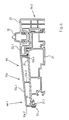
- the threshold 5 of the in the FIG. 2 generally designated 6 threshold profile 6, which is composed, inter alia, of a plurality of profile elements or sections, from a multi-chamber hollow or tubular profile profile section 7, which is made of a suitable plastic, such as an impact-resistant PVC, from a the underside of Threshold profile 6 forming and made of a suitable metallic material, such as aluminum or an aluminum alloy and also designed as a multi-chamber hollow profile reinforcing profile section 8 and a sims shamen, for example made of a metallic material profile section 9.
- the profile section 8 is received in the underside of the threshold profile 6 open towards recesses of the profile section 7 and connected there by locking with the profile section 7, in such a way that the profile section 8 in any case on the threshold profile inside 6.2, which is mounted on the building door 1 is located within the building, is covered by the profile section 7.
- the threshold profile 6 In the vicinity of the threshold profile inside 6.2 of the profile section 7 forms a step-like projection 7.1, to which a rail 10 is fixed for the sliding leaf 2.
- the projection 7.1 or the guide rail 10 define the closing plane of the building door 1.
- the threshold profile 6 protrudes over a large part of its width at the threshold profile outside 6.1.
- the guide rail 10 is designed such that it projects beyond the top of the step-like projection 7.1 at a height or threshold height which is smaller than the maximum permissible threshold height for a handicapped access area 11. which is a maximum of 20mm according to the valid standard.
- the (top) partially from the top of the profile section 7 in a region adjacent to the projection 7.1 and partially from the top of the profile section 8 in an edge region lying away from the projection 7.1 is formed in the passage area 11 of the building door 1 with open sliding sash 2 an additional profile 12 attached, which compensates for the entire height of the step-like projection 7.1 and forms with its top a slightly ramped to the projection 7.1 ramps and walk-surface.
- the additional profile 12, which, for example, of a metallic material, for example aluminum or an aluminum alloy or of a suitable plastic, for example made of impact-resistant PVC, is in the in the FIG. 2 illustrated embodiment by positive engagement in the profile section 7 and secured by locking.
- the additional profile 12 consists essentially of a plate-shaped, the top of the additional profile forming profile section 12.1 and three mutually parallel and spaced web-like profile sections 12.2, 12.3 and 12.4, which are made in one piece with the profile section 12.1 and 12.1 protrude from the underside of the profile section and determine the distance between the top of the threshold profile 6 and the top of the additional profile 12 with mounted additional profile 12.
- the two profile sections 12.2 and 12.4 are provided in each case at a longitudinal edge of the additional profile 12 and on a longitudinal side of the profile section 12.1, which is rectangular in plan view.
- the profile section 12.2 is supported with its lower, widened by an angled edge region on the top of the profile section 9, on the outer edge of this profile section such that the profile sections 12.3 and 12.4 opposite outer longitudinal side of the profile section 12.2 with mounted additional profile 12 in a common vertical or substantially vertical plane with the outside of an outer bend 9.1 formed on the profile section 9 is located.
- the profile section 12.4 is supported with a likewise angled lower edge region on the top of the profile section 7, in the vicinity of the transition to the step-like projection 7.1 and is there also with a over the entire length of the additional profile 12 extending nose or strip-like projection 13 provided, with which the mounted additional profile 12, the profile section 7 engages behind a vertical portion forming the step-like projection 7.1, in the form that the additional profile 12 is secured in the assembled state at the top of the threshold profile 6 against lifting.
- the projection 13 engages in a groove-shaped recess of a seal 14, which in a groove-shaped recess 15 is received, which is formed on the side facing the threshold profile outside 6.1 side of the projection 7.
- the seal 14 seals the connection between the additional profile and the profile section 7.
- the web-like profile section 12.3, which is provided approximately in the middle between the profile sections 12.2 and 12.4, serves on the one hand for further support of the additional profile 12 in the middle of the profile section 12.1 and on the other hand for locking the additional profile 12 at the top of the threshold profile 6 and the profile section 7.
- the profile section 12.3 is formed for this purpose at its lower free edge in an approximately S-shaped, in the form that it forms a support surface 16 there for abutment against the top of the profile section 7, then a recess 17 and then a web-like portion 18.
- the profile section 7 is provided on its upper side with a groove 19 extending in the longitudinal direction of the threshold profile 6, which on its side facing away from the projection 7.1 or at the local opening edge with a extending over the entire length of the threshold profile locking lug 20 is that when mounted Additional profile 12 engages latching into the recess 17.
- the profile section 12.3 is additionally supported in the region of the groove 19 on the profile section 7, namely on the oblique, perpendicular to the longitudinal extension of the section 18, the latching lug 20 opposite side surface of the groove 19th
- FIG. 6 shows as a further possible embodiment, a threshold profile 6a, which is used instead of the threshold profile 6 in the building door 1 and in the illustrated embodiment of a substantially the underside of the threshold profile 6a forming, designed as a multi-cavity profile support profile 21 of a metallic material, such as aluminum or an aluminum alloy and a likewise formed as a multi-cavity profile profile section 22 made of a suitable plastic, such as impact-resistant or impact-resistant PVC.
- the profile section 21 forms the mounted on the threshold profile 6a on the outside of the building, in Threshold profile longitudinally extending threshold profile outside 6a.1.
- the profiled section 22 forms the threshold profile inner side 6.2, which is also located in the threshold profiled longitudinal direction when the threshold profile 6a is mounted on the inside of the building. Both profile sections 21 and 22 are connected to one another by latching, in such a way that the profile section 22 completely covers the profile section 21 on the threshold profile inner side 6a.2 with a partial section having a plurality of hollow chambers, in particular for heat and sound insulation.
- the profile section 22 is further designed so that it forms on the upper side of the threshold profile 6a a step-like projection 22.1, to which in turn the guide rail 10 is fixed by latching, in such a way that the guide rail 10 with a measure on the top of the projection 22.1 protrudes, which is smaller than the allowable for a barrier-free training of the building door 1 step size.
- an additional profile 12a which initially differs from the additional profile in that the plate-shaped profile section 12a .1
- the web-like, mutually parallel and spaced-apart profile sections 12a.2 - 12a.4 are provided, but these profile sections are initially formed only for a support or support of the mounted additional profile 12a on the top of the profile section 21, namely the profile sections 12a.2 and 12a.4 each in turn with an angled foot area to increase the support or section area.
- the additional profile 12a of the profile section 12a.2 For attachment of the additional profile 12a of the profile section 12a.2 is provided with a over the entire length of the additional profile 12a extending strip-like extension 23 which is arranged with mounted additional profile 12a with their surface sides in vertical or substantially vertical planes and against the outside of a Abwinklung 21.1 is applied, the profile section 21 on the threshold profile outside 6.1.
- fasteners 24 for example by means of screws, in particular of self-tapping screws, the additional profile 11a is fastened with its extension 23 on the profile section 21 or on the bending there 21.1.
- the mounted additional profile 12a again forms on the upper side a passable and walkable surface, which is ramp-like and continuous, i. steplessly merges into the top of the projection 22.1, so that in the passage area 11, the barrier-free design of the threshold profile 6a and the threshold formed by this profile 5 is reached.
- the additional profile 11a is fixed to the threshold profile 6a by means of the fastening elements 24.
- the adhesive bond is made between the facing surfaces of the extension 23 and the bend as well as between the profile section 12a.4 and the top of the threshold profile 6a.
- this profile section is designed with a foot element 25 formed by a larger bend, which in the FIG. 6 is indicated by broken lines and also extends over the entire length of the additional profile 12a.
Landscapes
- Engineering & Computer Science (AREA)
- Civil Engineering (AREA)
- Structural Engineering (AREA)
- Wing Frames And Configurations (AREA)
Applications Claiming Priority (1)
| Application Number | Priority Date | Filing Date | Title |
|---|---|---|---|
| DE202008004204U DE202008004204U1 (de) | 2008-03-26 | 2008-03-26 | Schwelle für Gebäudetüren sowie Zusatzprofil zur Verwendung bei einer Schwelle bzw. einem Schwellenprofil für Gebäudetüren |
Publications (2)
| Publication Number | Publication Date |
|---|---|
| EP2105568A2 true EP2105568A2 (fr) | 2009-09-30 |
| EP2105568A3 EP2105568A3 (fr) | 2014-01-08 |
Family
ID=39587745
Family Applications (1)
| Application Number | Title | Priority Date | Filing Date |
|---|---|---|---|
| EP09003711.0A Withdrawn EP2105568A3 (fr) | 2008-03-26 | 2009-03-14 | Seuils pour portes de bâtiments et profilé supplémentaire destiné à l'utilisation avec un seuil ou un profilé de seuil pour portes de bâtiments |
Country Status (2)
| Country | Link |
|---|---|
| EP (1) | EP2105568A3 (fr) |
| DE (1) | DE202008004204U1 (fr) |
Cited By (1)
| Publication number | Priority date | Publication date | Assignee | Title |
|---|---|---|---|---|
| EP3225771A1 (fr) | 2016-03-31 | 2017-10-04 | HAUTAU GmbH | Seuil de porte pour une porte coulissante et porte coulissante |
Families Citing this family (2)
| Publication number | Priority date | Publication date | Assignee | Title |
|---|---|---|---|---|
| DE202009003392U1 (de) * | 2009-03-12 | 2009-06-10 | Veka Ag | Mehrteiliges Schwellenprofil für eine Hebeschiebetür |
| DE102015100586A1 (de) | 2015-01-15 | 2016-07-21 | SCHÜCO International KG | Schwelle für eine Gebäudeschiebetür und Rahmenprofil |
Citations (7)
| Publication number | Priority date | Publication date | Assignee | Title |
|---|---|---|---|---|
| US3900967A (en) | 1974-07-26 | 1975-08-26 | Pease Co | Adjustable sill and threshold assembly |
| US3967412A (en) | 1975-09-17 | 1976-07-06 | Peachtree Doors, Inc. | Adjustable threshold |
| US4079550A (en) | 1977-01-17 | 1978-03-21 | Pease Company | Composite sill assembly |
| US4831779A (en) | 1988-08-31 | 1989-05-23 | Schlegel Corporation | Self-draining panel threshold combination |
| EP1057961A2 (fr) | 1999-05-31 | 2000-12-06 | Gretsch Unitas GmbH Baubeschläge | Seuil pour porte de maison ainsi que porte de maison |
| DE20204563U1 (de) | 2002-03-21 | 2002-06-27 | Schüring GmbH & Co. Fenster-Technologie KG, 53842 Troisdorf | Thermisch isolierte Türschwelle |
| DE202004005204U1 (de) | 2004-03-30 | 2004-06-17 | Rehau Ag + Co. | Schiebetür |
Family Cites Families (2)
| Publication number | Priority date | Publication date | Assignee | Title |
|---|---|---|---|---|
| FR2832754B1 (fr) * | 2001-11-29 | 2004-09-24 | Rehau Sa | Seuil a rupture de pont thermique pour porte-fenetre et fermeture analogue |
| DE202004004979U1 (de) * | 2004-03-23 | 2004-06-03 | Gretsch-Unitas GmbH Baubeschläge | Bodenanschlussschwelle |
-
2008
- 2008-03-26 DE DE202008004204U patent/DE202008004204U1/de not_active Expired - Lifetime
-
2009
- 2009-03-14 EP EP09003711.0A patent/EP2105568A3/fr not_active Withdrawn
Patent Citations (7)
| Publication number | Priority date | Publication date | Assignee | Title |
|---|---|---|---|---|
| US3900967A (en) | 1974-07-26 | 1975-08-26 | Pease Co | Adjustable sill and threshold assembly |
| US3967412A (en) | 1975-09-17 | 1976-07-06 | Peachtree Doors, Inc. | Adjustable threshold |
| US4079550A (en) | 1977-01-17 | 1978-03-21 | Pease Company | Composite sill assembly |
| US4831779A (en) | 1988-08-31 | 1989-05-23 | Schlegel Corporation | Self-draining panel threshold combination |
| EP1057961A2 (fr) | 1999-05-31 | 2000-12-06 | Gretsch Unitas GmbH Baubeschläge | Seuil pour porte de maison ainsi que porte de maison |
| DE20204563U1 (de) | 2002-03-21 | 2002-06-27 | Schüring GmbH & Co. Fenster-Technologie KG, 53842 Troisdorf | Thermisch isolierte Türschwelle |
| DE202004005204U1 (de) | 2004-03-30 | 2004-06-17 | Rehau Ag + Co. | Schiebetür |
Cited By (2)
| Publication number | Priority date | Publication date | Assignee | Title |
|---|---|---|---|---|
| EP3225771A1 (fr) | 2016-03-31 | 2017-10-04 | HAUTAU GmbH | Seuil de porte pour une porte coulissante et porte coulissante |
| DE102016105941A1 (de) | 2016-03-31 | 2017-10-05 | Hautau Gmbh | Bodenschwelle für eine Schiebetür und Schiebetür |
Also Published As
| Publication number | Publication date |
|---|---|
| EP2105568A3 (fr) | 2014-01-08 |
| DE202008004204U1 (de) | 2008-07-03 |
Similar Documents
| Publication | Publication Date | Title |
|---|---|---|
| DE2139130A1 (de) | Fensterrahmen | |
| EP0785335A1 (fr) | Dispositif de support pour le bord d'un vitrage | |
| EP1057961B1 (fr) | Seuil pour porte de maison ainsi que porte de maison | |
| EP0833998B1 (fr) | Profile creux de cadre de fenetre et chassis de fenetre a deux battants utilisant ce profile | |
| DE202008004204U1 (de) | Schwelle für Gebäudetüren sowie Zusatzprofil zur Verwendung bei einer Schwelle bzw. einem Schwellenprofil für Gebäudetüren | |
| WO2011067210A2 (fr) | Paroi coulissante comportant au moins deux vantaux | |
| EP3543450B1 (fr) | Système de profilé de porte relevable et coulissante / coulissante | |
| DE20108555U1 (de) | Nut-Federverbindung von Dach- und Wandelementen | |
| EP0784144A1 (fr) | Joint magnétique pour porte et profilés annexes pour sa fabrication | |
| DE202004000817U1 (de) | Rahmenkörper aus einem hohlen, stranggepreßten Kunststoffprofil für Fenster und Türen | |
| EP0114218A2 (fr) | Fenêtre ou porte à listels bordé de bois ou de matière plastique | |
| AT17077U1 (de) | System zur Montage einer Fensterbank an einer Außenfassade | |
| DE102004036265A1 (de) | Befestigungselement für mehrteilige Rahmen für Fenster oder dergl. | |
| EP0017732B2 (fr) | Seuil, en particulier pour une fenêtre ou une porte | |
| DE2514694B2 (de) | Hölzerner Blendrahmen für Fenster oder Türen mit einem Abdeckprofil aus wetterfestem Material | |
| CH672000A5 (fr) | ||
| DE2750351A1 (de) | Profilkonstruktion | |
| DE2123984A1 (de) | Fenster, Tür oder dergleichen, deren Blendrahmen und Flügel auf der Innenseite aus Holz bestehen, welches auf der Außenseite durch Profile aus Metall oder Kunststoffabgedeckt ist | |
| EP2362047B1 (fr) | Porte à levage coulissante ou fenêtre à levage coulissant | |
| DE9206375U1 (de) | Tragwerk für Glasfassaden, -wände und/oder -dächer | |
| EP2060726A2 (fr) | Profilé creux | |
| DE10011576A1 (de) | Fenster- oder Türrahmen für Container o. dgl. | |
| DE3006987A1 (de) | Vorgefertigte fenster-zarge | |
| DE9011324U1 (de) | Vorrichtung zum Verschließen von Gebäudeöffnungen | |
| DE202004003535U1 (de) | Trockenbauwand |
Legal Events
| Date | Code | Title | Description |
|---|---|---|---|
| PUAI | Public reference made under article 153(3) epc to a published international application that has entered the european phase |
Free format text: ORIGINAL CODE: 0009012 |
|
| AK | Designated contracting states |
Kind code of ref document: A2 Designated state(s): AT BE BG CH CY CZ DE DK EE ES FI FR GB GR HR HU IE IS IT LI LT LU LV MC MK MT NL NO PL PT RO SE SI SK TR |
|
| AX | Request for extension of the european patent |
Extension state: AL BA RS |
|
| TPAC | Observations by third parties |
Free format text: ORIGINAL CODE: EPIDOSNTIPA |
|
| PUAL | Search report despatched |
Free format text: ORIGINAL CODE: 0009013 |
|
| AK | Designated contracting states |
Kind code of ref document: A3 Designated state(s): AT BE BG CH CY CZ DE DK EE ES FI FR GB GR HR HU IE IS IT LI LT LU LV MC MK MT NL NO PL PT RO SE SI SK TR |
|
| AX | Request for extension of the european patent |
Extension state: AL BA RS |
|
| RIC1 | Information provided on ipc code assigned before grant |
Ipc: E06B 1/70 20060101AFI20131205BHEP |
|
| AKY | No designation fees paid | ||
| REG | Reference to a national code |
Ref country code: DE Ref legal event code: R108 |
|
| REG | Reference to a national code |
Ref country code: DE Ref legal event code: R108 Effective date: 20140910 |
|
| STAA | Information on the status of an ep patent application or granted ep patent |
Free format text: STATUS: THE APPLICATION IS DEEMED TO BE WITHDRAWN |
|
| 18D | Application deemed to be withdrawn |
Effective date: 20140709 |