EP2105593A1 - Abgasbehandlungsvorrichtung, Verfahren zur Herstellung einer Abgasbehandlungsvorrichtung, Mattenelement und Verfahren zur Herstellung eines Mattenelements - Google Patents
Abgasbehandlungsvorrichtung, Verfahren zur Herstellung einer Abgasbehandlungsvorrichtung, Mattenelement und Verfahren zur Herstellung eines Mattenelements Download PDFInfo
- Publication number
- EP2105593A1 EP2105593A1 EP08165492A EP08165492A EP2105593A1 EP 2105593 A1 EP2105593 A1 EP 2105593A1 EP 08165492 A EP08165492 A EP 08165492A EP 08165492 A EP08165492 A EP 08165492A EP 2105593 A1 EP2105593 A1 EP 2105593A1
- Authority
- EP
- European Patent Office
- Prior art keywords
- exhaust gas
- gas treating
- mat member
- heating element
- treating apparatus
- Prior art date
- Legal status (The legal status is an assumption and is not a legal conclusion. Google has not performed a legal analysis and makes no representation as to the accuracy of the status listed.)
- Granted
Links
Images


Classifications
-
- F—MECHANICAL ENGINEERING; LIGHTING; HEATING; WEAPONS; BLASTING
- F01—MACHINES OR ENGINES IN GENERAL; ENGINE PLANTS IN GENERAL; STEAM ENGINES
- F01N—GAS-FLOW SILENCERS OR EXHAUST APPARATUS FOR MACHINES OR ENGINES IN GENERAL; GAS-FLOW SILENCERS OR EXHAUST APPARATUS FOR INTERNAL-COMBUSTION ENGINES
- F01N3/00—Exhaust or silencing apparatus having means for purifying, rendering innocuous, or otherwise treating exhaust
- F01N3/08—Exhaust or silencing apparatus having means for purifying, rendering innocuous, or otherwise treating exhaust for rendering innocuous
- F01N3/10—Exhaust or silencing apparatus having means for purifying, rendering innocuous, or otherwise treating exhaust for rendering innocuous by thermal or catalytic conversion of noxious components of exhaust
- F01N3/24—Exhaust or silencing apparatus having means for purifying, rendering innocuous, or otherwise treating exhaust for rendering innocuous by thermal or catalytic conversion of noxious components of exhaust characterised by constructional aspects of converting apparatus
- F01N3/28—Construction of catalytic reactors
- F01N3/2839—Arrangements for mounting catalyst support in housing, e.g. with means for compensating thermal expansion or vibration
- F01N3/2853—Arrangements for mounting catalyst support in housing, e.g. with means for compensating thermal expansion or vibration using mats or gaskets between catalyst body and housing
- F01N3/2864—Arrangements for mounting catalyst support in housing, e.g. with means for compensating thermal expansion or vibration using mats or gaskets between catalyst body and housing the mats or gaskets comprising two or more insulation layers
-
- B—PERFORMING OPERATIONS; TRANSPORTING
- B32—LAYERED PRODUCTS
- B32B—LAYERED PRODUCTS, i.e. PRODUCTS BUILT-UP OF STRATA OF FLAT OR NON-FLAT, e.g. CELLULAR OR HONEYCOMB, FORM
- B32B1/00—Layered products having a non-planar shape
- B32B1/08—Tubular products
-
- B—PERFORMING OPERATIONS; TRANSPORTING
- B32—LAYERED PRODUCTS
- B32B—LAYERED PRODUCTS, i.e. PRODUCTS BUILT-UP OF STRATA OF FLAT OR NON-FLAT, e.g. CELLULAR OR HONEYCOMB, FORM
- B32B15/00—Layered products comprising a layer of metal
- B32B15/14—Layered products comprising a layer of metal next to a fibrous or filamentary layer
-
- B—PERFORMING OPERATIONS; TRANSPORTING
- B32—LAYERED PRODUCTS
- B32B—LAYERED PRODUCTS, i.e. PRODUCTS BUILT-UP OF STRATA OF FLAT OR NON-FLAT, e.g. CELLULAR OR HONEYCOMB, FORM
- B32B15/00—Layered products comprising a layer of metal
- B32B15/18—Layered products comprising a layer of metal comprising iron or steel
-
- B—PERFORMING OPERATIONS; TRANSPORTING
- B32—LAYERED PRODUCTS
- B32B—LAYERED PRODUCTS, i.e. PRODUCTS BUILT-UP OF STRATA OF FLAT OR NON-FLAT, e.g. CELLULAR OR HONEYCOMB, FORM
- B32B3/00—Layered products comprising a layer with external or internal discontinuities or unevennesses, or a layer of non-planar shape; Layered products comprising a layer having particular features of form
- B32B3/02—Layered products comprising a layer with external or internal discontinuities or unevennesses, or a layer of non-planar shape; Layered products comprising a layer having particular features of form characterised by features of form at particular places, e.g. in edge regions
- B32B3/06—Layered products comprising a layer with external or internal discontinuities or unevennesses, or a layer of non-planar shape; Layered products comprising a layer having particular features of form characterised by features of form at particular places, e.g. in edge regions for securing layers together; for attaching the product to another member, e.g. to a support, or to another product, e.g. groove/tongue, interlocking
-
- B—PERFORMING OPERATIONS; TRANSPORTING
- B32—LAYERED PRODUCTS
- B32B—LAYERED PRODUCTS, i.e. PRODUCTS BUILT-UP OF STRATA OF FLAT OR NON-FLAT, e.g. CELLULAR OR HONEYCOMB, FORM
- B32B7/00—Layered products characterised by the relation between layers; Layered products characterised by the relative orientation of features between layers, or by the relative values of a measurable parameter between layers, i.e. products comprising layers having different physical, chemical or physicochemical properties; Layered products characterised by the interconnection of layers
- B32B7/04—Interconnection of layers
- B32B7/05—Interconnection of layers the layers not being connected over the whole surface, e.g. discontinuous connection or patterned connection
-
- F—MECHANICAL ENGINEERING; LIGHTING; HEATING; WEAPONS; BLASTING
- F01—MACHINES OR ENGINES IN GENERAL; ENGINE PLANTS IN GENERAL; STEAM ENGINES
- F01N—GAS-FLOW SILENCERS OR EXHAUST APPARATUS FOR MACHINES OR ENGINES IN GENERAL; GAS-FLOW SILENCERS OR EXHAUST APPARATUS FOR INTERNAL-COMBUSTION ENGINES
- F01N3/00—Exhaust or silencing apparatus having means for purifying, rendering innocuous, or otherwise treating exhaust
- F01N3/08—Exhaust or silencing apparatus having means for purifying, rendering innocuous, or otherwise treating exhaust for rendering innocuous
- F01N3/10—Exhaust or silencing apparatus having means for purifying, rendering innocuous, or otherwise treating exhaust for rendering innocuous by thermal or catalytic conversion of noxious components of exhaust
- F01N3/24—Exhaust or silencing apparatus having means for purifying, rendering innocuous, or otherwise treating exhaust for rendering innocuous by thermal or catalytic conversion of noxious components of exhaust characterised by constructional aspects of converting apparatus
- F01N3/28—Construction of catalytic reactors
- F01N3/2839—Arrangements for mounting catalyst support in housing, e.g. with means for compensating thermal expansion or vibration
- F01N3/2853—Arrangements for mounting catalyst support in housing, e.g. with means for compensating thermal expansion or vibration using mats or gaskets between catalyst body and housing
- F01N3/2857—Arrangements for mounting catalyst support in housing, e.g. with means for compensating thermal expansion or vibration using mats or gaskets between catalyst body and housing the mats or gaskets being at least partially made of intumescent material, e.g. unexpanded vermiculite
-
- B—PERFORMING OPERATIONS; TRANSPORTING
- B32—LAYERED PRODUCTS
- B32B—LAYERED PRODUCTS, i.e. PRODUCTS BUILT-UP OF STRATA OF FLAT OR NON-FLAT, e.g. CELLULAR OR HONEYCOMB, FORM
- B32B2255/00—Coating on the layer surface
- B32B2255/02—Coating on the layer surface on fibrous or filamentary layer
-
- B—PERFORMING OPERATIONS; TRANSPORTING
- B32—LAYERED PRODUCTS
- B32B—LAYERED PRODUCTS, i.e. PRODUCTS BUILT-UP OF STRATA OF FLAT OR NON-FLAT, e.g. CELLULAR OR HONEYCOMB, FORM
- B32B2255/00—Coating on the layer surface
- B32B2255/20—Inorganic coating
-
- B—PERFORMING OPERATIONS; TRANSPORTING
- B32—LAYERED PRODUCTS
- B32B—LAYERED PRODUCTS, i.e. PRODUCTS BUILT-UP OF STRATA OF FLAT OR NON-FLAT, e.g. CELLULAR OR HONEYCOMB, FORM
- B32B2260/00—Layered product comprising an impregnated, embedded, or bonded layer wherein the layer comprises an impregnation, embedding, or binder material
- B32B2260/02—Composition of the impregnated, bonded or embedded layer
- B32B2260/021—Fibrous or filamentary layer
-
- B—PERFORMING OPERATIONS; TRANSPORTING
- B32—LAYERED PRODUCTS
- B32B—LAYERED PRODUCTS, i.e. PRODUCTS BUILT-UP OF STRATA OF FLAT OR NON-FLAT, e.g. CELLULAR OR HONEYCOMB, FORM
- B32B2260/00—Layered product comprising an impregnated, embedded, or bonded layer wherein the layer comprises an impregnation, embedding, or binder material
- B32B2260/04—Impregnation, embedding, or binder material
- B32B2260/046—Synthetic resin
-
- B—PERFORMING OPERATIONS; TRANSPORTING
- B32—LAYERED PRODUCTS
- B32B—LAYERED PRODUCTS, i.e. PRODUCTS BUILT-UP OF STRATA OF FLAT OR NON-FLAT, e.g. CELLULAR OR HONEYCOMB, FORM
- B32B2262/00—Composition or structural features of fibres which form a fibrous or filamentary layer or are present as additives
- B32B2262/10—Inorganic fibres
-
- B—PERFORMING OPERATIONS; TRANSPORTING
- B32—LAYERED PRODUCTS
- B32B—LAYERED PRODUCTS, i.e. PRODUCTS BUILT-UP OF STRATA OF FLAT OR NON-FLAT, e.g. CELLULAR OR HONEYCOMB, FORM
- B32B2307/00—Properties of the layers or laminate
- B32B2307/30—Properties of the layers or laminate having particular thermal properties
-
- B—PERFORMING OPERATIONS; TRANSPORTING
- B32—LAYERED PRODUCTS
- B32B—LAYERED PRODUCTS, i.e. PRODUCTS BUILT-UP OF STRATA OF FLAT OR NON-FLAT, e.g. CELLULAR OR HONEYCOMB, FORM
- B32B2307/00—Properties of the layers or laminate
- B32B2307/50—Properties of the layers or laminate having particular mechanical properties
-
- B—PERFORMING OPERATIONS; TRANSPORTING
- B32—LAYERED PRODUCTS
- B32B—LAYERED PRODUCTS, i.e. PRODUCTS BUILT-UP OF STRATA OF FLAT OR NON-FLAT, e.g. CELLULAR OR HONEYCOMB, FORM
- B32B2597/00—Tubular articles, e.g. hoses, pipes
-
- B—PERFORMING OPERATIONS; TRANSPORTING
- B32—LAYERED PRODUCTS
- B32B—LAYERED PRODUCTS, i.e. PRODUCTS BUILT-UP OF STRATA OF FLAT OR NON-FLAT, e.g. CELLULAR OR HONEYCOMB, FORM
- B32B2605/00—Vehicles
-
- F—MECHANICAL ENGINEERING; LIGHTING; HEATING; WEAPONS; BLASTING
- F01—MACHINES OR ENGINES IN GENERAL; ENGINE PLANTS IN GENERAL; STEAM ENGINES
- F01N—GAS-FLOW SILENCERS OR EXHAUST APPARATUS FOR MACHINES OR ENGINES IN GENERAL; GAS-FLOW SILENCERS OR EXHAUST APPARATUS FOR INTERNAL-COMBUSTION ENGINES
- F01N2450/00—Methods or apparatus for fitting, inserting or repairing different elements
- F01N2450/28—Methods or apparatus for fitting, inserting or repairing different elements by using adhesive material, e.g. cement
-
- Y—GENERAL TAGGING OF NEW TECHNOLOGICAL DEVELOPMENTS; GENERAL TAGGING OF CROSS-SECTIONAL TECHNOLOGIES SPANNING OVER SEVERAL SECTIONS OF THE IPC; TECHNICAL SUBJECTS COVERED BY FORMER USPC CROSS-REFERENCE ART COLLECTIONS [XRACs] AND DIGESTS
- Y10—TECHNICAL SUBJECTS COVERED BY FORMER USPC
- Y10T—TECHNICAL SUBJECTS COVERED BY FORMER US CLASSIFICATION
- Y10T156/00—Adhesive bonding and miscellaneous chemical manufacture
- Y10T156/10—Methods of surface bonding and/or assembly therefor
Definitions
- the present invention relates generally to exhaust gas treating apparatuses and mat members used in exhaust gas treating apparatuses. More particularly, the present invention relates to an exhaust gas treating apparatus used for treating exhaust gas of a vehicle and a mat member used in such an exhaust gas treating apparatus.
- a typical exhaust gas treating apparatus includes an exhaust pipe communicating with an exhaust gas manifold of the engine. In the middle of the exhaust pipe, there is provided a casing made of, e.g., metal, and an exhaust gas treating body is provided inside the casing.
- the exhaust gas treating body has plural cells separated from one another by cell walls. These cells often have a honeycomb-like structure. If the exhaust gas treating body has a honeycomb-like structure, it is also referred to as a honeycomb structural body.
- Examples of an exhaust gas treating body are a catalyst carrier, an exhaust gas filter such as a diesel particulate filter (DPF), and the like. For example, if the exhaust gas treating body were a DPF, when the exhaust gas passes through the cells of the exhaust gas treating body, particulates would be captured by the cell walls due to the above configuration, and therefore the particulates can be removed from the exhaust gas.
- DPF diesel particulate filter
- an exhaust gas treating device is configured to have a mat member made of inorganic fiber provided between the exhaust gas treating body and the casing.
- This mat member prevents the exhaust gas treating body from breaking as a result of contacting the inside of the casing, which may occur while a vehicle is traveling.
- the mat member also prevents untreated exhaust gas from leaking through a gap between the casing and the exhaust gas treating body.
- the mat member also prevents the exhaust gas treating body from being displaced due to exhaust gas pressure. Furthermore, the mat member maintains the exhaust gas treating body at high temperature in order to maintain reactivity.
- the mat member is wound around at least a part of the peripheral surface of the exhaust gas treating body, except for its openings, and is integrally fixed to the exhaust gas treating body with the use of taping or the like. Then, this integrated component is press-fitted inside the casing, thereby configuring an exhaust gas treating apparatus.
- Patent document 1 Japanese Laid-Open Patent Application No. 2005-74243
- the positional displacement of the mat member with respect to the casing and/or the exhaust gas treating body does not only occur while manufacturing an exhaust gas treating apparatus.
- the exhaust gas treating apparatus is arranged in the middle of an exhaust pipe of an engine, when the engine operates, exhaust gas of high temperature (for example, 1000 °C at maximum) will flow through the exhaust gas treating apparatus, and when the engine stops operating, the exhaust gas will stop flowing through the exhaust gas treating apparatus. Due to this change in temperature, the casing and the exhaust gas treating body of the exhaust gas treating apparatus expand and contract, and therefore the mat member repeatedly receives compression/decompression loads in the radial direction of the exhaust gas treating body. Usually, the amount of damaged inorganic fiber included in the mat member increases due to repeatedly receiving such loads. Thus, the holding force of the mat member decreases with the passage of time. When the holding force of the mat member drops below a minimum holding force with respect to the exhaust gas treating body, the position of the mat member becomes displaced with respect to the metal casing and/or the exhaust gas treating body.
- high temperature for example, 1000 °C at maximum
- the latex provided on both surfaces of the mat member entirely burns away due to the heat of the exhaust gas within a relatively short period of time after starting to use the exhaust gas treating apparatus.
- the holding force of the mat member of patent document 1 decreases with the passage of time after starting using the exhaust gas treating apparatus, just like any regular mat member.
- the present invention provides an exhaust gas treating apparatus, a method of manufacturing the exhaust gas treating apparatus, a mat member, and a method of manufacturing the mat member in which one or more of the above-described disadvantages are eliminated.
- a preferred embodiment of the present invention provides an exhaust gas treating apparatus and a method of manufacturing the exhaust gas treating apparatus, in which the positional displacement of a mat member with respect to an exhaust gas treating body and a casing is mitigated, even after being used for a long period of time. Furthermore, a preferred embodiment of the present invention provides a mat member and a method of manufacturing the mat member, in which the positional displacement of the mat member with respect to an exhaust gas treating body and a casing is mitigated, when the mat member is used in an exhaust gas treating apparatus.
- An embodiment of the present invention provides an exhaust gas treating apparatus including an exhaust gas treating body; a mat member including inorganic fiber, the mat member being wound around at least a part of a peripheral surface of the exhaust gas treating body; a casing configured to accommodate the exhaust gas treating body around which the mat member is wound; and a heating element configured to emit heat, the heating element being provided at least one of between the exhaust gas treating body and the mat member and between the mat member and the casing.
- An embodiment of the present invention provides a method of manufacturing an exhaust gas treating apparatus including an exhaust gas treating body, a mat member including inorganic fiber, the mat member being wound around at least a part of a peripheral surface of the exhaust gas treating body, and a casing configured to accommodate the exhaust gas treating body around which the mat member is wound, the method including a heating element providing step of providing a heating element configured to emit heat, at least one of between the exhaust gas treating body and the mat member and between the mat member and the casing.
- An embodiment of the present invention provides a mat member including a first main surface; a second main surface; inorganic fiber; and a heating element configured to emit heat, the heating element being provided on at least one of the first main surface and the second main surface.
- An embodiment of the present invention provides a method of manufacturing a mat member including a first main surface, a second main surface, and inorganic fiber, the method including a heating element providing step of providing a heating element configured to emit heat, the heating element being provided on at least one of the first main surface and the second main surface.
- an exhaust gas treating apparatus and a method of manufacturing the exhaust gas treating apparatus are provided, in which the positional displacement of a mat member with respect to an exhaust gas treating body and a casing is mitigated, even after being used for a long period of time. Furthermore, according to one embodiment of the present invention, a mat member and a method of manufacturing the mat member are provided, in which the positional displacement of the mat member with respect to an exhaust gas treating body and a casing is mitigated, when the mat member is used in an exhaust gas treating apparatus.
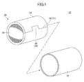
- FIG. 1 is a schematic perspective view of an exhaust gas treating apparatus in a disassembled state according to the present invention.
- FIG. 2 is a schematic cross-sectional view of a vertical plane with respect to the axial (longitudinal) direction of the exhaust gas treating apparatus shown in FIG. 1 .
- the example of the exhaust gas treating apparatus shown in FIG. 1 is manufactured by a press-fitting method.
- the exhaust gas treating apparatus may be manufactured by another method, such as a clamshell method, a winding-tightening method, a sizing method, or the like.
- an exhaust gas treating apparatus 10 includes an exhaust gas treating body 20, a mat member 24 wound around the peripheral surface of the exhaust gas treating body 20, and a casing 12 for accommodating the exhaust gas treating body 20 around which the mat member 24 is wound (hereinafter, "integrated exhaust gas treating body 25").
- the exhaust gas treating body 20 is, for example, a catalyst carrier having plural through holes extending in a direction parallel to the longitudinal direction.
- a catalyst is supported by each of the cell walls made of ceramics forming a honeycomb structure, for example.
- the exhaust gas treating body 20 may be a DPF having plural through holes extending in a direction parallel to the longitudinal direction, in which the ends of the through holes are sealed in a checkered manner at both of the opening faces of the exhaust gas treating body 20.
- FIG. 3 illustrates an example of the mat member 24.
- the mat member 24 includes a first main surface 250 and a second main surface 260. Furthermore, the mat member 24 includes two edge faces 70 and 71 perpendicular to the direction in which the sheet member 24 is wound (X direction in FIG. 3 ).
- the edge faces 70 and 71 have a mating protruding part 50 and a mating receding part 60, respectively.
- the mating protruding part 50 is mated to the mating receding part 60, and the mat member 24 is fixed to the exhaust gas treating body 20.
- the edge faces 70 and 71 of the mat member 24 are fixed with the use of adhesive tape or the like so that the mated part does not become detached while handling the "integrated exhaust gas treating body 25".
- the mat member 24 constitutes a mat-like component including inorganic fiber. Any kind of inorganic fiber may be used; however, inorganic fiber including alumina and silica is typically used. If the mat member 24 were only made of inorganic fiber, the bulk of the mat member 24 would increase, and it would be difficult to handle the mat member 24. Therefore, the mat member 24 is usually impregnated with an organic binder.
- the casing 12 constitutes metal such as stainless steel, nickel alloy, or the like.
- the exhaust gas treating apparatus 10 includes a first heating element 80 provided at an interface 79 of the mat member 24 and the case 12, and a second heating element 90 provided at an interface 89 of the exhaust gas treating body 20 and the mat member 24, although not shown in FIG. 1 nor described with reference to FIG. 1 as a matter of clarification.
- the first heating element 80 and the second heating element 90 are provided at both interfaces 79 and 89, respectively; however, either one may be omitted.
- first heating element 80 may be provided across the entire interface 79 and the second heating element 90 may be provided across the entire interface 89, respectively, or the first heating element 80 may be provided at a part of the interface 79 and the second heating element 90 may be provided at a part of the interface 89, respectively.
- the first and second heating elements 80 and 90 have features of emitting heat when the temperature exceeds a predetermined value.
- the first and second heating elements 80 and 90 constitute a substance that generates a significant exothermic reaction in a temperature region where the temperature exceeds a predetermined value.
- exhaust gas of high temperature typically 400 °C through 1000 °C
- exhaust gas of high temperature typically 400 °C through 1000 °C
- the casing and the exhaust gas treating body of the exhaust gas treating apparatus expand/contract, and therefore the mat member repeatedly receives compression/decompression loads in the radial direction of the exhaust gas treating body from both main surfaces.
- the amount of damaged inorganic fiber included in the mat member increases due to repeatedly receiving such loads.
- the holding force of the mat member decreases with the passage of time.
- the mat member can no longer hold the exhaust gas treating body.
- the exhaust gas treating body or the mat member becomes displaced from the predetermined position, and therefore the exhaust gas treating apparatus may not be able to effectively treat the exhaust gas.
- the exhaust gas treating apparatus 10 includes the first heating element 80 and the second heating element 90 which are provided at the interface 79 and the interface 89, respectively.
- the first heating element 80 and the second heating element 90 are heated by heat of the exhaust gas that enters the exhaust gas treating body 20 while the exhaust gas treating apparatus 10 is being used.
- the temperature of the first heating element 80 and the second heating element 90 exceeds a predetermined value, heat is emitted from the first heating element 80 and the second heating element 90.
- the temperature of the positions where the first heating element 80 and the second heating element 90 are disposed and neighboring positions increases acutely due to the heat emitted from the heating elements.
- the first heating element 80 is provided at the interface 79 of the mat member 24 and the casing 12
- the temperature rises locally and acutely at a position on the casing 12 in contact with or close to the first heating element 80 and neighboring positions (hereinafter, "high temperature contact position").
- this "high temperature contact position" exceeds the melting point of the material of the inner surface of the casing 12
- the inner surface of the casing 12 melts, and molten material is formed.
- the molten material generated from the casing 12 moves, in a molten state, toward the outer surface of the mat member 24 (e.g., the first main surface 250) facing the inner surface of the casing 12.
- the molten material enters inside the mat member 24 from the outer surface of the mat member 24.
- the distance between the molten material and the first heating element 80 increases, and as this distance increases, the temperature of the molten material decreases.
- the temperature of the molten material falls below its melting point. Accordingly, the molten material starts solidifying. For example, when the first heating element 80 stops generating heat as the substance contributing to heat generation disappears, the local increase in temperature of the casing 12 stops, and the formation of molten material will stop.
- the interface 79 of the mat member 24 and the casing 12 will finally have the form as illustrated in FIG. 4 . That is, a molten-solidified layer 275 will be formed at the interface 79, extending from the first main surface 250 of the mat member in the depth direction of the mat member.
- the molten-solidified layer 275 contributes to enhancing the bonding strength of the casing 12 and the mat member 24.
- the molten-solidified layer 275 is solidified with many inorganic fibers 270 of the mat member 24 captured in the molten-solidified layer 275, so that the molten-solidified layer 275 firmly bonds together the mat member 24 and the casing 12.
- the molten-solidified layer 275 extends inside the mat member 24, and therefore the mat member 24 has favorable resistance with respect to a force in the lateral direction (longitudinal direction) of the exhaust gas treating apparatus. Accordingly, once the molten-solidified layer 275 is formed, the positional displacement of the mat member 24 with respect to the casing 12 hardly occurs. It is particularly noted that this effect is maintained even as features of a typical mat member changes with the passage of time, i.e., even as the amount of damaged inorganic materials included in the mat member increases with the passage of time.
- the positional displacement of components hardly occurs for a longer period of time compared to conventional exhaust gas treating apparatuses.
- the surface roughness of the inner surface of the casing 12 will be relatively high.
- the increase in surface roughness contributes to the increase in the friction coefficient with respect to the movement of the mat member 24 along the longitudinal direction of the exhaust gas treating apparatus. Accordingly, assuming that the mat member 24 receives large stress in this direction from outside and part of the molten-solidified layer 275 breaks, the rough surface of the casing 12 will continue to mitigate the positional displacement of the mat member, thereby attaining a significant effect.
- the second heating element 90 at the interface 89 between the mat member 24 and the exhaust gas treating body 20.
- the inner surface of the casing 12 usually constitutes metal
- the peripheral surface of the exhaust gas treating body 20 constitutes ceramics such as cordierite or the like, which has a higher melting point than that of metal.
- the heat value of the second heating element 90 is preferably higher than that of the first heating element 80.
- Such a heating element may emit heat according to an exothermic chemical reaction.
- a preferable chemical reaction to be selected for this configuration is a chemical reaction that occurs at a temperature range of the exhaust gas (e.g., 450 °C through 1000 °C) . Accordingly, when the exhaust gas flows through, the exothermic reaction starts immediately, thus attaining the above-described effect.
- the starting material used for the chemical reaction is preferably configured to form a liquid at the above-described temperature range of exhaust gas, i.e., the starting material preferably has a melting point within this range.
- the chemical reaction can be quickly generated.
- the reaction of liquid/solid or liquid/liquid is faster than that of solid/solid.
- the melting point of the product generated as a result of the chemical reaction is preferably higher than the above-described temperature range of exhaust gas. If the product is in a liquid-phase state, the molten material of the casing or the exhaust gas treating body is mixed with this product, which may hamper the movement of the molten material toward the mat member.
- the product generated as a result of the chemical reaction may be a product that sublimates or volatilizes in the above-described temperature range of exhaust gas. In this case, it is possible to mitigate the reaction product from hampering the movement of the molten material toward the mat member.
- the heat generation density of the heating element (heat value per unit area at the interface 79 or the interface 89) may be in a range of 0.1 kJ/cm 2 through 0.4 kJ/cm 2 , although this depends on the melting target. These values depend on the melting point, the melting amount, the melting area and the like of the melting target.
- the starting material necessary for the reaction may be any of the various material systems described below.
- Combinations of metal and an inorganic compound include, for example, a combination of aluminum and oxide, nitride, carbide, or the like.
- the oxide may be, for example, iron oxide, titanium oxide, or the like.
- the nitride may be titanium oxide, silicon nitride, titanium nitride, zirconium nitride, hafnium nitride, vanadium nitride, niobium nitride, tantalum nitride, or the like.
- the carbide may be boron carbide, aluminum carbide, or the like.
- FIG. 5 shows examples of combinations of metals and inorganic compounds, together with melting points of the products.
- the reaction heat is a negative value (e.g., the reaction heat ⁇ H of the reaction of No. 1 is -851.5 kJ/mol), which means that these reactions are exothermic reactions.
- each combination may be used as the starting material of the above-described heating element.
- the melting point of aluminum used as one of the starting materials for each reaction is approximately 660 °C, which is equal to or lower than the temperature of exhaust gas described above.
- the melting point of the product of each reaction is at least 1350 °C (e.g., the cases of Nos. 3 and 5), which is higher than the temperature of exhaust gas.
- a mixture of a first metal (or alloy) and a second metal (or alloy) may be used as the starting material necessary for a chemical reaction.
- the first metal aluminum may be used.
- the second metal may include steel, titanium, zirconium, hafnium, vanadium, niobium, tantalum, nickel, and the like.
- FIG. 6 shows examples of combinations of a first metal (or alloy) and a second metal (or alloy), together with melting points of the products.
- the reaction heat is a negative value, which means that these reactions are exothermic reactions. Accordingly, each combination may be used as the starting material of the above-described heating element.
- the melting point of aluminum used as one of the starting materials for each reaction is approximately 660 °C, which is equal to or lower than the temperature of exhaust gas described above.
- the melting point of the product of each reaction is at least 1145 °C (e.g., the cases of No. 1), which is higher than the temperature of exhaust gas.
- each of the above combination examples two kinds of materials are used as the starting materials; however, the combinations of the heating element according to the present invention are not limited thereto.
- three kinds of materials may be used as the starting materials.
- FIG. 7 shows examples of such combinations, together with melting points of the products.
- the reaction heat is a negative value, which means that these reactions are exothermic reactions. Accordingly, each combination may be used as the starting material of the above-described heating element.
- the melting point of aluminum used as one of the starting materials for each reaction is approximately 660 °C, which is equal to or lower than the temperature of exhaust gas described above.
- the melting point of the product of each reaction is at least 1390 °C (Al 3 Ti), which is higher than the temperature of exhaust gas.
- a substance having a function of mitigating oxidation of aluminum and/or a function deoxidizing an oxide film on the surface of aluminum Accordingly, the exothermic reaction can be attained more quickly (or at a lower temperature).
- a substance having such functions are Mg, Ca, Li, and the like.
- metallic elements are taken as examples of metals used as the starting material; however, the metal used as the starting material may be an alloy.
- the metal used as the starting material may be an alloy.
- Al-Cu alloy, Al-Mn alloy, Al-Si alloy, and Al-Mg alloy have melting points of approximately 550 °C., 660 °C, 580 °C, and 450 °C, respectively.
- the first heating element 80 and the second heating element 90 may be provided at the interfaces 79 and 89, respectively, by any method such as brush painting, spray painting, or the like. Furthermore, the heating element may be provided at the interfaces 79 and 89 in any form, such as powder, a sheet, a layer, or the like. Particularly, when a heating element that uses exothermic heat generated by a chemical reaction is to be provided, starting materials necessary for a chemical reaction are turned into powder, and the powder may be provided across the entire interface or at a part of the interface. Alternatively, the powder may be mixed with an organic solvent to prepare a liquid or a paste, and this mixture may be applied to the interfaces 79 and 89.
- the first heating element 80 and the second heating element 90 may be provided on any surface that forms an interface when the exhaust gas treating apparatus is completed, such as the inner surface of the casing 12, the first main surface 250 and/or the second main surface 260 of the mat member 24, the peripheral surface of the exhaust gas treating body 20, or the like.
- a first starting material necessary for a chemical reaction is provided on the inner surface of the casing 12, and a second starting material is provided on one of the main surfaces of the mat member 24, or the other way around. Accordingly, at the stage of manufacturing the exhaust gas treating apparatus, when the first starting material and the second starting material contact each other or come close to each other, the first heating element 80 is formed at the interface 79. The same applies to the peripheral surface of the exhaust gas treating body 20 and the other main surface of the mat member 24.
- FIG. 8 is an example of a flowchart of a method of manufacturing the exhaust gas treating apparatus in which a heating element is provided on the interface 79 and/or the interface 89 by the above method. It is to be noted that in FIG. 8 , the "first (second) starting material" may be a single material or may include plural materials.
- the present invention is not limited to such an embodiment.
- the above-described molten-solidified layer 275 may be formed at the interface 79 and/or the interface 89 by placing the exhaust gas treating apparatus having the above-described configuration in an electric furnace or the like before actually using the exhaust gas treating apparatus, and keeping the exhaust gas treating apparatus in a high temperature to activate the heating element (so called "thermal pretreatment method").
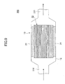
- FIG. 9 illustrates an example of an application of the exhaust gas treating apparatus according to the present invention.
- the exhaust gas treating apparatus 10 is provided in the middle of an exhaust pipe 200 for discharging exhaust gas generated by an engine of a vehicle or the like outside the system.
- the exhaust pipe 200 includes an inlet pipe 210 and an outlet pipe 220 for the exhaust gas.
- the exhaust gas treating apparatus 10 according to the present invention is provided between the inlet pipe 210 and the outlet pipe 220.
- the inlet pipe 210 and the outlet pipe 220 are taper-shaped in such a manner that their diameters are increased at positions at which they are connected to the casing 12 of the exhaust gas treating apparatus 10. However, they do not necessarily need to be taper-shaped.
- the exhaust gas treating apparatus has a configuration in which positional displacement hardly occurs among the components of the exhaust gas treating body, the mat member, and the casing. Therefore, exhaust gas treatment properties can be stably attained for a long period of time.
- the effects of the present invention are described as follows. Specifically, in the above-described example, heat is generated from the first heating element 80 and/or the second heating element 90 provided at the interface 79 of the casing 12/mat member 24 and/or the interface 89 of the mat member 24/exhaust gas treating body 20, respectively. Part of the components (the casing or the exhaust gas treating body) melts due to this heat, thereby forming a molten-solidified layer.
- this phenomenon is described only as one example so that the present invention is easily understood. That is, the first heating element 80 and the second heating element 90 provided at the interfaces 79 and 89, respectively, may exhibit behaviors different from the above phenomenon.
- the heating element of No. 1 shown in FIG. 5 which uses aluminum and iron oxide as starting materials, is provided at the interface 79 of the casing 12/mat member 24.
- the aluminum included in the heating element starts to melt.
- the molten aluminum may move from the surface of the mat member 24 toward the inside of the mat member 24. Accordingly, part of the molten aluminum may cover part of the inorganic fiber included in the mat member 24.
- the alumina which is a reaction product of the heating element, is generated as a result of the reaction of the aluminum in a molten state.
- alumina is generated wherever the aluminum is present, also inside the mat member 24. Therefore, when the molten aluminum, which is covering a part of the inorganic fiber included in the mat member, changes to a layer of a reaction product (i.e., an alumina layer) as a result of this reaction, the inorganic fiber is captured in the alumina layer.
- a reaction product i.e., an alumina layer
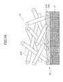
- FIG. 10 illustrates the final interface 79 attained as a result of such a phenomenon.
- part of the inorganic fibers 270 is captured by a reaction product layer 276.
- the mat member 24 and the casing are firmly bonded to each other by the reaction product layer 276 which is the final product, and therefore the same effects as above can be achieved.
- the casing 12 has not undergone the melting process.
- the present invention may be any kind of exhaust gas treating apparatus in which the first heating element 80 and the second heating element 90 are provided at the interfaces 79 and 89, respectively, regardless of the kind of phenomenon that may occur at the interfaces 79 and 89.
- a mat member 30 according to the present invention basically has the same configuration as the mat member 24 described above.
- the mat member 30 has a heating element 81 and a heating element 91 provided on a first main surface 251 and a second main surface 261, respectively.
- the heating elements 81 and 91 have the above-described functions; for example, when the temperature exceeds a predetermined value, the heating elements are activated and they generate heat.
- the heating elements 81 and 91 may be partially or entirely (as illustrated in FIG. 11 ) provided on the first main surface 251 and the second main surface 261, respectively.
- the heating elements 81 and 91 are provided as layers on both main surfaces 251 and 261, respectively.
- the heating elements may be provided in forms other than layers; for example, powder may be sprinkled on the main surfaces 251 and 261.
- a heating element may be provided on only one of the main surface 251 and 261.
- This mat member 30 may further have a sheet member including an organic compound provided on the main surface on which the heating element is provided, to improve the convenience in handling the mat member 30. This is extremely effective when the heating element is in a form other than a layer.
- the mat member 30 with such a heating element is wound around the exhaust gas treating body, and is inserted inside a casing to form an "integrated exhaust gas treating body", thereby configuring the exhaust gas treating apparatus.
- the heating element is activated by heat of the exhaust gas, and the heating element emits heat toward the peripheral surface of the exhaust gas treating body and/or the inner surface of the casing. Accordingly, in this case also, the bonding strength at the interface between the exhaust gas treating body and the mat member and/or the bonding strength at the interface between the mat member and the casing will increase due to the function of the molten-solidified layer 275 or the reaction product layer 276, thereby attaining the same effects as described above.
- This mat member is advantageous in that heating elements can be easily provided at the interface between the exhaust gas treating body and the mat member and at the interface between the mat member and the casing.
- FIG. 12 is a flowchart of a method of manufacturing the mat member according to the present invention.
- the method of manufacturing the mat member according to the present invention includes a step of providing the mat member including inorganic fiber (step S210) and a step of providing the heating element 81 and/or the heating element 91 on at least part of the first main surface 251 and/or the second main surface 261 of the mat member, respectively (step S220). Detailed descriptions of both steps are given below.
- a laminated sheet including inorganic fiber is manufactured.
- a mixture of alumina and silica is used as the inorganic fiber; however, the material of the inorganic fiber is not limited thereto.
- the inorganic fiber may be made of only alumina or only silica.
- the composition ratio of alumina:silica is more preferably 70 through 74:30 through 26. If the relative proportion of alumina is less than 60%, the composition ratio of the mullite, which is generated from alumina and silica, will decrease. Accordingly, the completed base sheet will tend to have high heat conductivity.
- an organic polymer such as polyvinyl alcohol is added to this precursor of alumina fiber. Subsequently, this liquid is concentrated to prepare a spinning solution. This spinning solution is used in a spinning operation performed by a blowing method.
- the blowing method is a spinning method performed with the use of airflows blown out from air nozzles and spinning solution flows pressed out from spinning solution supplying nozzles.
- the gas flow speed from slits of each air nozzle is usually 40 m/s through 200 m/s.
- the diameter of each spinning solution supplying nozzle is usually 0.1 mm through 0.5 mm, and the liquid amount per spinning solution supplying nozzle is usually around 1 ml/h through 120 ml/h, more preferably around 3 ml/h through 50 ml/h. Under such conditions, the spinning solution pressed out from the spinning solution supplying nozzles will be sufficiently extended without turning into a spray form (mist form), and the fibers will not be deposited onto each other. Accordingly, by optimizing the spinning conditions, it is possible to form a uniform precursor with a narrow fiber diameter distribution.
- the average fiber length of the alumina fibers manufactured herein is preferably more than or equal to 250 ⁇ m, and more preferably more than or equal to 500 ⁇ m. If the average fiber length were less than 250 ⁇ m, the fibers would not be sufficiently intertwined, and the strength would be insufficient.
- the average diameter of the inorganic fibers is not particularly limited; the inorganic fibers preferably have an average diameter in a range of approximately 3 ⁇ m through approximately 8 ⁇ m, more preferably in a range of approximately 5 ⁇ m through approximately 7 ⁇ m.
- the precursors that have undergone the spinning process are laminated to each other so that a laminated sheet is manufactured. Then, needling processing is performed on the laminated sheet. Needling processing is performed by inserting and pulling out needles to and from the laminated sheet to thin down the laminated sheet. A needling device is usually used for the needling processing.
- a needling device includes a needle board capable of reciprocating (usually up and down) in the direction in which needles are inserted in and pulled out from the laminated sheet, and a pair of supporting plates disposed on the side of the top main surface and on the side of the bottom main surface of the laminated sheet.
- the needle plate has multiple needles to be inserted in the laminated sheet, which needles are arranged at a density of, for example, approximately 25 needles/100 cm 2 through 5,000 needles/100 cm 2 .
- Each supporting plate has multiple through holes for the needles.
- the needle board In a state where the pair of supporting plates is pressed against both sides of the laminated sheet, the needle board is moved toward and away from the laminated sheet. Accordingly, the needles are inserted in and pulled out from the laminated sheet, and multiple needle traces are formed in the interlaced fibers.
- the needling device may include a set of two needle boards.
- Each needle board has a corresponding support plate.
- the two needle boards are respectively disposed on the top surface and the bottom surface of the laminated sheet, so that the laminated sheet is held by the supporting plates on both sides.
- the needles on one of the needle boards are arranged in such a manner that their positions do not coincide with those on the other needle board during the needling processing.
- each of the support plates has multiple through holes that are arranged in consideration of the positions of the needles on each of the needle boards, so that the needles do not abut the support plate when the needling processing is performed from both sides of the laminated sheet.
- Such a device can be used to sandwich the laminated sheet from both sides with the two supporting plates and perform the needling processing from both sides of the laminated sheet with the two needle boards. With such a method of needling processing, the process time can be reduced.
- the laminated sheet formed by the above needling processing is heated from normal temperature, and is continuously fired at a maximum temperature of approximately 1,250 °C to form a mat member having a predetermined volume density (weight per unit area).
- the formed mat member is impregnated with an organic binder such as resin from one or both of the main surfaces.
- an organic binder such as resin from one or both of the main surfaces.
- the amount of the organic binder included in the mat member is preferably as small as possible, preferably within a range of, for example, 1.0 wt% through 4.0 wt%.
- organic binder examples include epoxy resin, acrylic resin, rubber resin, styrene resin, or the like.
- Preferable examples are acrylic (ACM) resin, acrylonitrile-butadiene rubber (NBR) resin, styrene-butadiene rubber (SBR) resin, or the like.
- the mat member manufactured as above is cut into a predetermined shape (for example, the shape illustrated in FIG. 11 ).
- a heating element is partially or entirely provided on the first main surface.
- An example of a method of providing the heating member on the mat member is described below, taking as an example the heating element having a function of generating heat in response to a chemical reaction.
- the heating element raw material may be formed by mixing together particles of starting materials necessary for the chemical reaction such as those indicated in FIGS. 5 through 7 , by a predetermined mixing ratio. Under normal circumstances, this mixing ratio is selected according to reaction stoichiometry. For example, in the case of the reaction system of No. 1 in FIG. 5 , aluminum powder and iron oxide (Fe 2 O 3 ) powder are mixed together so that the molar ratio is 2:1.
- the heating element raw material is mixed together with an organic solvent to prepare a liquid such as slurry, a turbid medium, or the like.
- the heating element raw material and the organic solvent may be mixed together by various existing methods.
- the resultant liquid is sprayed or brushed onto a first main surface of a mat member, thereby providing a heating element on the first main surface.
- the mat member may subsequently undergo thermal treatment in order to vaporize the organic solvent.
- the heating element raw material may be sprinkled on the first surface of the mat member as a powder.
- the raw material powder may scatter or drop.
- a polymer film, a polymer sheet, or the like is preferably provided on the first main surface to cover the heating element raw material.
- the same process may be performed to partially or entirely provide a heating element on the second main surface of the mat member, which heating element may be the same kind as that of the first main surface or a different kind from that of the first main surface.
- a mat member which has a heating element provided on at least one of its main surfaces.
- Aluminum powder manufactured by Kishida Chemical Co., Ltd., purity 90%
- the powders were put in a mortar, acetone was added to the powders, and this was mixed together for 60 minutes. Subsequently, this mixture was put in a drying machine and was dried for one hour in 110 °C, thereby attaining a powder mixture for the heating element.
- polyvinyl alcohol was added to this precursor of alumina fiber.
- this liquid was concentrated to prepare a spinning solution.
- This spinning solution was used in a spinning operation performed by a blowing process.
- the flow rate of the conveying carrier gas (air) was 52 m/s and the supplying speed of the spinning solution was 5.3 ml/h.
- the precursors of alumina fiber were folded and laminated to each other so that a raw material sheet of alumina fiber was manufactured.
- the needling processing was performed from one side of the raw material sheet by disposing a needle board, on which needles are arranged at a density of 80 needles/100 cm 2 , only on the side of one of the main surfaces of the raw material sheet.
- the resultant raw material sheet was continuously fired at a temperature ranging from a normal temperature to a maximum temperature of 1,250 °C for an hour, thereby forming the mat member.
- the mat member formed in the above manner having a thickness of 7.4 mm and a basis weight of 1240 g/m 2 , was cut to a size of length 50 mm ⁇ width 40 mm, thereby manufacturing a test mat member.
- This mat member does not include an organic binder.
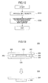
- the mat member manufactured by the above method was used to manufacture an evaluation test sample 310 shown in FIG. 13 by the following method.
- the above-described powder mixture was applied entirely on one of the main surfaces (area of 50 mm x ⁇ 40 mm) of the mat member manufactured by the above-described method, so that the application amount was 75 mg/cm 2 .
- This application amount corresponds to 0.3 kJ/cm 2 when converted to heat generation density.
- a mat member 325 covered by a powder mixture 320 was placed in the center of a stainless steel plate (SUS 304) 330 having a size of length 150 mm ⁇ width 40 mm ⁇ thickness 1 mm, in such a manner that the surface covered by the powder mixture 320 is facing upward.
- metal spacers 340 each having the same thickness as that of the mat member 325, were provided on both edges of the mat member 325.
- another stainless steel plate (SUS 304) 350 having a size of length 150 mm ⁇ width 40 mm ⁇ thickness 1 mm was arranged on top of these components, in such a manner as to overlap the position of the stainless steel plate 330 in the direction of laminated layers.
- a metal wire 360 was wound around each of the edges of the stainless steel plates 330 and 350 to fix the components together, thereby forming an assembly 300.
- This assembly 300 was put in an atmosphere electric furnace, and was kept in there for 10 minutes at a temperature of 1000 °C. Subsequently, the assembly 300 was removed from the electrical furnace and was naturally cooled. The metal wires 360 used for fixing the components were removed from the resultant assembly 300, so that the components were separated from one another. Finally a test sample 310 was formed, in which the stainless steel plate 350 and the mat member 325 were joined together.
- Example 2 By the same method as example 1, a test sample was manufactured. However, in example 2, the application amount of the powder mixture on the surface of the mat member was 25 mg/cm 2 . This application amount corresponds to 0.1 kJ/cm 2 when converted to heat generation density. The other conditions were the same as those of example 1.
- Example 3 the application amount of the powder mixture on the surface of the mat member was 50 mg/cm 2 . This application amount corresponds to 0.2 kJ/cm 2 when converted to heat generation density.
- the other conditions were the same as those of example 1.
- Example 4 By the same method as example 1, a test sample was manufactured. However, in example 4, the application amount of the powder mixture on the surface of the mat member was 100 mg/cm 2 . This application amount corresponds to 0.4 kJ/cm 2 when converted to heat generation density. The other conditions were the same as those of example 1.
- Example 5 By the same method as example 1, a test sample was manufactured. However, in example 5, the application amount of the powder mixture on the surface of the mat member was 150 mg/cm 2 . This application amount corresponds to 0.6 kJ/cm 2 when converted to heat generation density. The other conditions were the same as those of example 1.
- the metal wires used for fixing the components were removed from the resultant assembly.
- the stainless steel plate 350 and the mat member 325 were not joined together at all.
- an inorganic fiber mat member (length 50 mm x width 40 mm x thickness 7.4 mm) was manufactured. On one of the main surfaces of this mat member (area of 50 mm x 40 mm), a high polymer material was provided. The application amount was 0.8 mg/cm 2 .
- a styrene-butadiene adhesive (spray type adhesive Z-2 manufactured by Konishi Co., Ltd.) was used as the high polymer material.
- test sample was manufactured by the same method as example 1. However, after being kept in an atmosphere electric furnace for 10 minutes at a temperature of 1000 °C, the stainless steel plate 350 and the mat member 325 were not joined together at all.
- Table 1 indicates the manufacturing conditions and the state after heat treatment for all of the test samples of the examples and comparative examples.
- Table 1 POWDER MIXTURE FOR GENERATG HEAT APPLICATION AMOUNT [mg/cm 2 ] HEAT GENERATION DENSITY [kJ/cm 2 ] STATE OF DEPOSITION STATE OF STAINLESS STEAL PLATE BONDING STRENGTH [N/cm 2 ] METAL INORGANIC COMPOUND MOLAR RATIO EXAMPLE 1 Al Fe 2 O 3 2:1 75 0.3 GOOD GOOD 2.38 EXAMPLE 2 Al Fe 2 O 3 2:1 25 0.1 GOOD GOOD 1.84 EXAMPLE 3 Al Fe 2 O 3 2:1 50 0.2 GOOD GOOD 2.14 EXAMPLE 4 Al Fe 2 O 3 2:1 100 0.4 GOOD GOOD 2.95 EXAMPLE 5 Al Fe 2 O 3 2:1 150 0.6 GOOD DEFORMED 3.77 COMPARATIVE EXAMPLE 1 - - - - - GOOD 0.96 COMPARATIVE EXAMPLE 2 APPLY HIGH POLY
- the bonding strength between the mat member and the stainless steel plate was evaluated for each of the test samples (examples 1 through 5 and comparative examples 1 and 2) manufactured by the above method.
- the evaluation of the bonding strength was performed with a testing apparatus 400 shown in FIG. 14 .
- the testing apparatus 400 includes a center plate 410 that can move up and down, a fixed plate 450 provided on the same axis as the center plate 410 and fixed at this position, and two pressing tools 480.
- the center plate 410, the fixed plate 450, and the pressing tools 480 are made of stainless steel.
- Attachment members 420 are respectively provided on the front side and back side of the center plate 410 at positions corresponding to each other. On each attachment member 420, on the surface opposite to that in contact with the center plate 410, multiple needle-like protruding parts are provided, extending in a substantially perpendicular direction with respect to each surface of the center plate 410. The full length of each needle-like protruding part is approximately 2 mm.
- the length and width of each of the attachment members 420 are substantially the same as those of the above-described mat member 325 (to be more precise, the attachment member 420 has a size of length 50 mm x width 40 mm, but is somewhat larger than the mat member 325).
- the pressing tools 480 are made of rectangular planks, and each of the pressing tools 480 has openings corresponding to bolt holes at four corners. Furthermore, the fixed plate 450 also has openings corresponding to bolt holes at two predetermined positions.
- each evaluation test sample 310 was fixed to the surface of one of the pressing tools 480.
- Each evaluation test sample 310 was fixed, with the use of double-faced adhesive tape or the like, in such a manner that the side of the stainless steel plate 350 of the evaluation test sample 310 was in contact with the pressing tool 480.
- the pressing tools 480 were disposed on both sides of the center plate 410, in such a manner that the evaluation test samples 310 were located inside the center plate 410 and the pressing tools 480. More specifically, the pressing tools 480 were disposed in such a manner that the surfaces of the mat members 325 of the evaluation test samples 310 were in contact with the surfaces of the attachment members 420. As described above, needle-like protruding parts are provided on the surfaces of the attachment members 420. With the use of these protruding parts, each evaluation test sample 310 was fixed to the center plate 410.
- the center plate 410 is pulled upwards.
- the positions of the fixed plate 450 and the pressing tools 480 fixed to the fixed plate 450 do not change. Accordingly, by moving the center plate 410, the interface of the mat member 325 and the stainless steel plate 350 receives a shearing force, and therefore it is possible to evaluate the bonding strength at the interface of the mat member 325 and the stainless steel plate 350 by performing this test.
- bonding strength N / cm 2 maximum load N / area of mat member cm 2 ⁇ 2
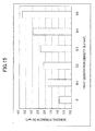
- FIG. 15 illustrates the relationship between heat generation densities of the powder mixture and bonding strengths. This diagram shows that as the heat generation density of the powder mixture increases, the bonding strength increases. However, as indicated by example 5 in Table 1, if the heat generation density was too high, the bonding target that is to be bonded with the mat member would deteriorate or deform due to the heat. Accordingly, the heat generation density is preferably less than 0.6 kJ/cm.
- the exhaust gas treating apparatus according to the present invention is applicable to a vehicle or the like.
- an exhaust gas treating apparatus includes an exhaust gas treating body; a mat member including inorganic fiber, the mat member being wound around at least a part of a peripheral surface of the exhaust gas treating body; a casing configured to accommodate the exhaust gas treating body around which the mat member is wound; and a heating element configured to emit heat, the heating element being provided at least one of between the exhaust gas treating body and the mat member and between the mat member and the casing.
- the heating element can emit heat in such a manner that at least one of the exhaust gas treating body and the casing melts near the heating element.
- the heating element can be provided as a powder or as a layer, on at least a part of at least one of the exhaust gas treating body, the mat member, and the casing.
- the heating element can be provided in a state bound by an organic binder.
- the heating element can emit the heat in response to an exothermic chemical reaction.
- a metal or an alloy, and an inorganic compound can be used as starting materials for the chemical reaction.
- the inorganic compound can include iron oxide.
- a first metal or a first alloy and a second metal or a second alloy can be used as the starting materials for the chemical reaction.
- At least one material included in the starting materials can have a melting point falling in a range of 450 °C through 1000 °C.
- the starting materials can include aluminum or an aluminum alloy.
- a product of the chemical reaction can have a melting point that exceeds 1000 °C.
- the exhaust gas treating body can include a catalyst carrier or an exhaust gas filter.
- a method of manufacturing an exhaust gas treating apparatus including an exhaust gas treating body, a mat member including inorganic fiber, the mat member being wound around at least a part of a peripheral surface of the exhaust gas treating body, and a casing configured to accommodate the exhaust gas treating body around which the mat member is wound, includes a heating element providing step of providing a heating element configured to emit heat, at least one of between the exhaust gas treating body and the mat member and between the mat member and the casing.
- the heating element providing step can further include a step of providing the heating element as a powder or as a layer, on at least a part of at least one of the exhaust gas treating body, the mat member, and the casing.
- the heating element can be provided in a state bound by an organic binder.
- the heating element can emit the heat in response to an exothermic chemical reaction.
- the heating element providing step can further include a step of providing a first starting material on a first surface of at least one of the exhaust gas treating body, the mat member, and the casing; a step of providing a second starting material on a second surface that comes in contact with or comes close to the first surface onto which the first starting material is provided when the exhaust gas treating apparatus is completed; and a step of bringing the fist starting material and the second starting material in contact with each other.
- the method can further include a step of increasing the temperature of the exhaust gas treating apparatus so that the temperature of the exhaust gas treating apparatus falls in a range of 450 °C through 1000 °C.
- the step of increasing the temperature of the exhaust gas treating apparatus so that the temperature of the exhaust gas treating apparatus falls in a range of 450 °C through 1000 °C can further include a step of causing exhaust gas to flow through the exhaust gas treating apparatus.
- the exhaust gas treating body can include a catalyst carrier or an exhaust gas filter.
- a mat member includes a first main surface; a second main surface; inorganic fiber; and a heating element configured to emit heat, the heating element being provided on at least one of the first main surface and the second main surface.
- the heating element can be provided as a powder or as a layer.
- the heating element can be provided in a state bound by an organic binder.
- the heating element can emit the heat in response to an exothermic chemical reaction.
- the heating element can be provided in such a manner that a heat generation density per unit area falls in a range of 0.1 kJ/cm 2 through 0.4 4 kJ/cm 2 .
- a metal or an alloy, and an inorganic compound can be used as starting materials for the chemical reaction.
- the inorganic compound can include iron oxide.
- a first metal or a first alloy and a second metal or a second alloy can be used as the starting materials for the chemical reaction.
- At least one material included in the starting materials can have a melting point falling in a range of 450 °C through 1000 °C.
- the metal can include aluminum or an aluminum alloy.
- a product of the chemical reaction can have a melting point that exceeds 1000 °C.
- a method of manufacturing a mat member including a first main surface, a second main surface, and inorganic fiber includes a heating element providing step of providing a heating element configured to emit heat, the heating element being provided on at least one of the first main surface and the second main surface.
- the heating element providing step further includes a step of providing the heating element as a powder or as a layer, on a surface of at least one of the first main surface and the second main surface.
- the heating element can be provided in a state bound by an organic binder.
- the heating element can emit the heat in response to an exothermic chemical reaction.
Landscapes
- Chemical & Material Sciences (AREA)
- Engineering & Computer Science (AREA)
- Chemical Kinetics & Catalysis (AREA)
- Mechanical Engineering (AREA)
- Combustion & Propulsion (AREA)
- Toxicology (AREA)
- Health & Medical Sciences (AREA)
- General Engineering & Computer Science (AREA)
- Exhaust Gas After Treatment (AREA)
- Exhaust Gas Treatment By Means Of Catalyst (AREA)
- Processes For Solid Components From Exhaust (AREA)
- Solid-Sorbent Or Filter-Aiding Compositions (AREA)
- Diaphragms For Electromechanical Transducers (AREA)
- External Artificial Organs (AREA)
- Gas-Filled Discharge Tubes (AREA)
Priority Applications (1)
| Application Number | Priority Date | Filing Date | Title |
|---|---|---|---|
| EP11155573A EP2336516B1 (de) | 2008-03-27 | 2008-09-30 | Mattenelement |
Applications Claiming Priority (1)
| Application Number | Priority Date | Filing Date | Title |
|---|---|---|---|
| JP2008084611A JP5164633B2 (ja) | 2008-03-27 | 2008-03-27 | 排気ガス処理装置およびその製造方法 |
Related Child Applications (1)
| Application Number | Title | Priority Date | Filing Date |
|---|---|---|---|
| EP11155573.6 Division-Into | 2011-02-23 |
Publications (2)
| Publication Number | Publication Date |
|---|---|
| EP2105593A1 true EP2105593A1 (de) | 2009-09-30 |
| EP2105593B1 EP2105593B1 (de) | 2011-04-20 |
Family
ID=40085568
Family Applications (2)
| Application Number | Title | Priority Date | Filing Date |
|---|---|---|---|
| EP08165492A Active EP2105593B1 (de) | 2008-03-27 | 2008-09-30 | Abgasbehandlungsvorrichtung und entsprechendes Herstellungsverfahren |
| EP11155573A Active EP2336516B1 (de) | 2008-03-27 | 2008-09-30 | Mattenelement |
Family Applications After (1)
| Application Number | Title | Priority Date | Filing Date |
|---|---|---|---|
| EP11155573A Active EP2336516B1 (de) | 2008-03-27 | 2008-09-30 | Mattenelement |
Country Status (6)
| Country | Link |
|---|---|
| US (1) | US20090246095A1 (de) |
| EP (2) | EP2105593B1 (de) |
| JP (1) | JP5164633B2 (de) |
| CN (1) | CN101543727B (de) |
| AT (2) | ATE506526T1 (de) |
| DE (1) | DE602008006352D1 (de) |
Cited By (2)
| Publication number | Priority date | Publication date | Assignee | Title |
|---|---|---|---|---|
| EP2784283A3 (de) * | 2013-03-26 | 2015-08-19 | Ibiden Co., Ltd. | Haltendes Dichtungsmaterial für eine Abgasreinigungsvorrichtung, Herstellungsverfahren von haltendem Dichtungsmaterial, Abgasreinigungskatalysatorvorrichtung, und Verfahren zur Herstellung der Abgasreinigungsvorrichtung |
| EP2784284A3 (de) * | 2013-03-26 | 2015-08-19 | Ibiden Co., Ltd. | Haltedichtungsmaterial, Verfahren zur Herstellung des Haltedichtungsmaterial, Abgasreinigungsvorrichtung und Verfahren zur Herstellung einer Abgasreinigungsvorrichtung |
Families Citing this family (7)
| Publication number | Priority date | Publication date | Assignee | Title |
|---|---|---|---|---|
| JP5014113B2 (ja) * | 2007-01-26 | 2012-08-29 | イビデン株式会社 | シート材、その製造方法、排気ガス処理装置および消音装置 |
| CN103079701B (zh) * | 2010-09-10 | 2014-10-08 | 丰田自动车株式会社 | 电加热式催化剂 |
| US9924564B2 (en) | 2010-11-11 | 2018-03-20 | Unifrax I Llc | Heated mat and exhaust gas treatment device |
| EP2740914B1 (de) * | 2011-08-05 | 2020-01-22 | Nichias Corporation | Halter für gasverarbeitungsvorrichtung, gasverarbeitungsvorrichtung und herstellungsverfahren dafür |
| CN115680847A (zh) * | 2018-06-21 | 2023-02-03 | 3M创新有限公司 | 垫材料、其制造方法、污染控制装置和隔热结构 |
| EP3881064A1 (de) * | 2018-11-15 | 2021-09-22 | Corning Incorporated | Ultraschallprüfung für keramische strukturen |
| JP2020097901A (ja) * | 2018-12-17 | 2020-06-25 | イビデン株式会社 | 保持シール材及び保持シール材の製造方法 |
Citations (2)
| Publication number | Priority date | Publication date | Assignee | Title |
|---|---|---|---|---|
| EP0574012A2 (de) * | 1992-06-10 | 1993-12-15 | Shimadzu Corporation | Konstruktion einer katalytischen Auspuff-Gas-Reinigungs-Anlage |
| US5413766A (en) | 1991-10-04 | 1995-05-09 | Leistritz Ag & Co. Abgastechnik | Device for reducing exhaust gas contaminants, particularly for motor vehicles |
Family Cites Families (9)
| Publication number | Priority date | Publication date | Assignee | Title |
|---|---|---|---|---|
| JPS60212611A (ja) * | 1984-04-06 | 1985-10-24 | Suzuki Motor Co Ltd | 触媒体の保持方法 |
| JP3056747B2 (ja) * | 1989-05-08 | 2000-06-26 | 臼井国際産業株式会社 | 排気ガス浄化装置 |
| US5322671A (en) * | 1992-02-25 | 1994-06-21 | Blue Planet Technologies Co., L.P. | Catalytic vessel |
| JP3715127B2 (ja) * | 1999-02-22 | 2005-11-09 | 本田技研工業株式会社 | 触媒コンバータ |
| US20020127154A1 (en) * | 2000-03-03 | 2002-09-12 | Foster Michael R. | Exhaust control device and method for manufacture thereof |
| DE60118421T2 (de) * | 2000-11-10 | 2006-08-17 | Ibiden Co., Ltd. | Abgaskatalysator, Verfahren zu seiner Herstellung und Halte-und Dichtungsmaterial für Katalysatoren |
| US20030129102A1 (en) * | 2002-01-08 | 2003-07-10 | Turek Alan Gerard | Exhaust emissions control devices comprising adhesive |
| JP2005074243A (ja) * | 2003-08-29 | 2005-03-24 | Three M Innovative Properties Co | 汚染コントロール要素の保持材及び汚染コントロール装置 |
| JP4665618B2 (ja) * | 2005-06-10 | 2011-04-06 | イビデン株式会社 | 保持シール材の製造方法 |
-
2008
- 2008-03-27 JP JP2008084611A patent/JP5164633B2/ja not_active Expired - Fee Related
- 2008-09-23 CN CN2008101658130A patent/CN101543727B/zh active Active
- 2008-09-29 US US12/240,797 patent/US20090246095A1/en not_active Abandoned
- 2008-09-30 AT AT08165492T patent/ATE506526T1/de not_active IP Right Cessation
- 2008-09-30 AT AT11155573T patent/ATE557173T1/de active
- 2008-09-30 EP EP08165492A patent/EP2105593B1/de active Active
- 2008-09-30 DE DE602008006352T patent/DE602008006352D1/de active Active
- 2008-09-30 EP EP11155573A patent/EP2336516B1/de active Active
Patent Citations (2)
| Publication number | Priority date | Publication date | Assignee | Title |
|---|---|---|---|---|
| US5413766A (en) | 1991-10-04 | 1995-05-09 | Leistritz Ag & Co. Abgastechnik | Device for reducing exhaust gas contaminants, particularly for motor vehicles |
| EP0574012A2 (de) * | 1992-06-10 | 1993-12-15 | Shimadzu Corporation | Konstruktion einer katalytischen Auspuff-Gas-Reinigungs-Anlage |
Cited By (2)
| Publication number | Priority date | Publication date | Assignee | Title |
|---|---|---|---|---|
| EP2784283A3 (de) * | 2013-03-26 | 2015-08-19 | Ibiden Co., Ltd. | Haltendes Dichtungsmaterial für eine Abgasreinigungsvorrichtung, Herstellungsverfahren von haltendem Dichtungsmaterial, Abgasreinigungskatalysatorvorrichtung, und Verfahren zur Herstellung der Abgasreinigungsvorrichtung |
| EP2784284A3 (de) * | 2013-03-26 | 2015-08-19 | Ibiden Co., Ltd. | Haltedichtungsmaterial, Verfahren zur Herstellung des Haltedichtungsmaterial, Abgasreinigungsvorrichtung und Verfahren zur Herstellung einer Abgasreinigungsvorrichtung |
Also Published As
| Publication number | Publication date |
|---|---|
| EP2336516B1 (de) | 2012-05-09 |
| CN101543727B (zh) | 2012-01-11 |
| DE602008006352D1 (de) | 2011-06-01 |
| EP2336516A1 (de) | 2011-06-22 |
| CN101543727A (zh) | 2009-09-30 |
| JP5164633B2 (ja) | 2013-03-21 |
| ATE557173T1 (de) | 2012-05-15 |
| EP2105593B1 (de) | 2011-04-20 |
| JP2009236047A (ja) | 2009-10-15 |
| US20090246095A1 (en) | 2009-10-01 |
| ATE506526T1 (de) | 2011-05-15 |
Similar Documents
| Publication | Publication Date | Title |
|---|---|---|
| EP2336516B1 (de) | Mattenelement | |
| KR101497865B1 (ko) | 오염 제어 요소용 보유 재료 및 오염 제어 장치 | |
| EP1717218B1 (de) | Wabenstruktur | |
| EP2328674B1 (de) | Montageunterlage mit flexiblem kantenschutz und abgasbearbeitungsvorrichtung mit der montageunterlage | |
| US8951323B2 (en) | Multiple layer mat and exhaust gas treatment device | |
| EP2603676B1 (de) | Montageunterlage mit flexiblem kantenschutz und abgasbearbeitungsvorrichtung mit der montageunterlage | |
| EP1738813A1 (de) | Wabenstruktur | |
| WO2006013651A1 (ja) | 焼成炉及びこれを用いた多孔質セラミック部材の製造方法 | |
| EP1772600B1 (de) | Halteabdichtung und Abgasbehandlungsvorrichtung | |
| CN101155978B (zh) | 污染控制元件安装部件和污染控制装置 | |
| EP1759754B1 (de) | Verfahren zur herstellung eines filters für abgasreinigungssystem | |
| EP1832729B1 (de) | Faserschichtbauteil und Abgasreinigungsvorrichtung beinhaltend dieses als Lagermatte | |
| KR100993447B1 (ko) | 배기 가스 처리 장치, 그 제조 방법, 매트재 및 그 제조 방법 | |
| EP4077892B1 (de) | Verfahren zur herstellung einer wärmedämmstruktur | |
| JP2011241837A (ja) | シート材および排気ガス浄化装置 |
Legal Events
| Date | Code | Title | Description |
|---|---|---|---|
| PUAI | Public reference made under article 153(3) epc to a published international application that has entered the european phase |
Free format text: ORIGINAL CODE: 0009012 |
|
| 17P | Request for examination filed |
Effective date: 20080930 |
|
| AK | Designated contracting states |
Kind code of ref document: A1 Designated state(s): AT BE BG CH CY CZ DE DK EE ES FI FR GB GR HR HU IE IS IT LI LT LU LV MC MT NL NO PL PT RO SE SI SK TR |
|
| AX | Request for extension of the european patent |
Extension state: AL BA MK RS |
|
| 17Q | First examination report despatched |
Effective date: 20100118 |
|
| AKX | Designation fees paid |
Designated state(s): AT BE BG CH CY CZ DE DK EE ES FI FR GB GR HR HU IE IS IT LI LT LU LV MC MT NL NO PL PT RO SE SI SK TR |
|
| GRAP | Despatch of communication of intention to grant a patent |
Free format text: ORIGINAL CODE: EPIDOSNIGR1 |
|
| RTI1 | Title (correction) |
Free format text: EXHAUST GAS TREATING APPARATUS AND CORRESPONDING METHOD OF MANUFACTURING. |
|
| GRAS | Grant fee paid |
Free format text: ORIGINAL CODE: EPIDOSNIGR3 |
|
| GRAA | (expected) grant |
Free format text: ORIGINAL CODE: 0009210 |
|
| AK | Designated contracting states |
Kind code of ref document: B1 Designated state(s): AT BE BG CH CY CZ DE DK EE ES FI FR GB GR HR HU IE IS IT LI LT LU LV MC MT NL NO PL PT RO SE SI SK TR |
|
| REG | Reference to a national code |
Ref country code: GB Ref legal event code: FG4D |
|
| REG | Reference to a national code |
Ref country code: CH Ref legal event code: EP |
|
| REG | Reference to a national code |
Ref country code: IE Ref legal event code: FG4D |
|
| REF | Corresponds to: |
Ref document number: 602008006352 Country of ref document: DE Date of ref document: 20110601 Kind code of ref document: P |
|
| REG | Reference to a national code |
Ref country code: DE Ref legal event code: R096 Ref document number: 602008006352 Country of ref document: DE Effective date: 20110601 |
|
| REG | Reference to a national code |
Ref country code: NL Ref legal event code: VDEP Effective date: 20110420 |
|
| LTIE | Lt: invalidation of european patent or patent extension |
Effective date: 20110420 |
|
| PG25 | Lapsed in a contracting state [announced via postgrant information from national office to epo] |
Ref country code: HR Free format text: LAPSE BECAUSE OF FAILURE TO SUBMIT A TRANSLATION OF THE DESCRIPTION OR TO PAY THE FEE WITHIN THE PRESCRIBED TIME-LIMIT Effective date: 20110420 Ref country code: LT Free format text: LAPSE BECAUSE OF FAILURE TO SUBMIT A TRANSLATION OF THE DESCRIPTION OR TO PAY THE FEE WITHIN THE PRESCRIBED TIME-LIMIT Effective date: 20110420 Ref country code: SE Free format text: LAPSE BECAUSE OF FAILURE TO SUBMIT A TRANSLATION OF THE DESCRIPTION OR TO PAY THE FEE WITHIN THE PRESCRIBED TIME-LIMIT Effective date: 20110420 Ref country code: PT Free format text: LAPSE BECAUSE OF FAILURE TO SUBMIT A TRANSLATION OF THE DESCRIPTION OR TO PAY THE FEE WITHIN THE PRESCRIBED TIME-LIMIT Effective date: 20110822 Ref country code: NO Free format text: LAPSE BECAUSE OF FAILURE TO SUBMIT A TRANSLATION OF THE DESCRIPTION OR TO PAY THE FEE WITHIN THE PRESCRIBED TIME-LIMIT Effective date: 20110720 |
|
| PG25 | Lapsed in a contracting state [announced via postgrant information from national office to epo] |
Ref country code: FI Free format text: LAPSE BECAUSE OF FAILURE TO SUBMIT A TRANSLATION OF THE DESCRIPTION OR TO PAY THE FEE WITHIN THE PRESCRIBED TIME-LIMIT Effective date: 20110420 Ref country code: LV Free format text: LAPSE BECAUSE OF FAILURE TO SUBMIT A TRANSLATION OF THE DESCRIPTION OR TO PAY THE FEE WITHIN THE PRESCRIBED TIME-LIMIT Effective date: 20110420 Ref country code: BE Free format text: LAPSE BECAUSE OF FAILURE TO SUBMIT A TRANSLATION OF THE DESCRIPTION OR TO PAY THE FEE WITHIN THE PRESCRIBED TIME-LIMIT Effective date: 20110420 Ref country code: CY Free format text: LAPSE BECAUSE OF FAILURE TO SUBMIT A TRANSLATION OF THE DESCRIPTION OR TO PAY THE FEE WITHIN THE PRESCRIBED TIME-LIMIT Effective date: 20110420 Ref country code: ES Free format text: LAPSE BECAUSE OF FAILURE TO SUBMIT A TRANSLATION OF THE DESCRIPTION OR TO PAY THE FEE WITHIN THE PRESCRIBED TIME-LIMIT Effective date: 20110731 Ref country code: GR Free format text: LAPSE BECAUSE OF FAILURE TO SUBMIT A TRANSLATION OF THE DESCRIPTION OR TO PAY THE FEE WITHIN THE PRESCRIBED TIME-LIMIT Effective date: 20110721 Ref country code: IS Free format text: LAPSE BECAUSE OF FAILURE TO SUBMIT A TRANSLATION OF THE DESCRIPTION OR TO PAY THE FEE WITHIN THE PRESCRIBED TIME-LIMIT Effective date: 20110820 Ref country code: AT Free format text: LAPSE BECAUSE OF FAILURE TO SUBMIT A TRANSLATION OF THE DESCRIPTION OR TO PAY THE FEE WITHIN THE PRESCRIBED TIME-LIMIT Effective date: 20110420 Ref country code: SI Free format text: LAPSE BECAUSE OF FAILURE TO SUBMIT A TRANSLATION OF THE DESCRIPTION OR TO PAY THE FEE WITHIN THE PRESCRIBED TIME-LIMIT Effective date: 20110420 |
|
| PG25 | Lapsed in a contracting state [announced via postgrant information from national office to epo] |
Ref country code: NL Free format text: LAPSE BECAUSE OF FAILURE TO SUBMIT A TRANSLATION OF THE DESCRIPTION OR TO PAY THE FEE WITHIN THE PRESCRIBED TIME-LIMIT Effective date: 20110420 |
|
| PG25 | Lapsed in a contracting state [announced via postgrant information from national office to epo] |
Ref country code: EE Free format text: LAPSE BECAUSE OF FAILURE TO SUBMIT A TRANSLATION OF THE DESCRIPTION OR TO PAY THE FEE WITHIN THE PRESCRIBED TIME-LIMIT Effective date: 20110420 Ref country code: CZ Free format text: LAPSE BECAUSE OF FAILURE TO SUBMIT A TRANSLATION OF THE DESCRIPTION OR TO PAY THE FEE WITHIN THE PRESCRIBED TIME-LIMIT Effective date: 20110420 |
|
| PLBE | No opposition filed within time limit |
Free format text: ORIGINAL CODE: 0009261 |
|
| STAA | Information on the status of an ep patent application or granted ep patent |
Free format text: STATUS: NO OPPOSITION FILED WITHIN TIME LIMIT |
|
| PG25 | Lapsed in a contracting state [announced via postgrant information from national office to epo] |
Ref country code: DK Free format text: LAPSE BECAUSE OF FAILURE TO SUBMIT A TRANSLATION OF THE DESCRIPTION OR TO PAY THE FEE WITHIN THE PRESCRIBED TIME-LIMIT Effective date: 20110420 Ref country code: SK Free format text: LAPSE BECAUSE OF FAILURE TO SUBMIT A TRANSLATION OF THE DESCRIPTION OR TO PAY THE FEE WITHIN THE PRESCRIBED TIME-LIMIT Effective date: 20110420 Ref country code: PL Free format text: LAPSE BECAUSE OF FAILURE TO SUBMIT A TRANSLATION OF THE DESCRIPTION OR TO PAY THE FEE WITHIN THE PRESCRIBED TIME-LIMIT Effective date: 20110420 Ref country code: RO Free format text: LAPSE BECAUSE OF FAILURE TO SUBMIT A TRANSLATION OF THE DESCRIPTION OR TO PAY THE FEE WITHIN THE PRESCRIBED TIME-LIMIT Effective date: 20110420 |
|
| 26N | No opposition filed |
Effective date: 20120123 |
|
| PG25 | Lapsed in a contracting state [announced via postgrant information from national office to epo] |
Ref country code: MC Free format text: LAPSE BECAUSE OF NON-PAYMENT OF DUE FEES Effective date: 20110930 |
|
| REG | Reference to a national code |
Ref country code: DE Ref legal event code: R097 Ref document number: 602008006352 Country of ref document: DE Effective date: 20120123 |
|
| PG25 | Lapsed in a contracting state [announced via postgrant information from national office to epo] |
Ref country code: IT Free format text: LAPSE BECAUSE OF FAILURE TO SUBMIT A TRANSLATION OF THE DESCRIPTION OR TO PAY THE FEE WITHIN THE PRESCRIBED TIME-LIMIT Effective date: 20110420 |
|
| REG | Reference to a national code |
Ref country code: IE Ref legal event code: MM4A |
|
| PG25 | Lapsed in a contracting state [announced via postgrant information from national office to epo] |
Ref country code: IE Free format text: LAPSE BECAUSE OF NON-PAYMENT OF DUE FEES Effective date: 20110930 |
|
| PG25 | Lapsed in a contracting state [announced via postgrant information from national office to epo] |
Ref country code: MT Free format text: LAPSE BECAUSE OF FAILURE TO SUBMIT A TRANSLATION OF THE DESCRIPTION OR TO PAY THE FEE WITHIN THE PRESCRIBED TIME-LIMIT Effective date: 20110420 |
|
| REG | Reference to a national code |
Ref country code: CH Ref legal event code: PL |
|
| PG25 | Lapsed in a contracting state [announced via postgrant information from national office to epo] |
Ref country code: LU Free format text: LAPSE BECAUSE OF NON-PAYMENT OF DUE FEES Effective date: 20110930 |
|
| PG25 | Lapsed in a contracting state [announced via postgrant information from national office to epo] |
Ref country code: BG Free format text: LAPSE BECAUSE OF FAILURE TO SUBMIT A TRANSLATION OF THE DESCRIPTION OR TO PAY THE FEE WITHIN THE PRESCRIBED TIME-LIMIT Effective date: 20110720 |
|
| PG25 | Lapsed in a contracting state [announced via postgrant information from national office to epo] |
Ref country code: LI Free format text: LAPSE BECAUSE OF NON-PAYMENT OF DUE FEES Effective date: 20120930 Ref country code: CH Free format text: LAPSE BECAUSE OF NON-PAYMENT OF DUE FEES Effective date: 20120930 |
|
| PG25 | Lapsed in a contracting state [announced via postgrant information from national office to epo] |
Ref country code: TR Free format text: LAPSE BECAUSE OF FAILURE TO SUBMIT A TRANSLATION OF THE DESCRIPTION OR TO PAY THE FEE WITHIN THE PRESCRIBED TIME-LIMIT Effective date: 20110420 |
|
| PG25 | Lapsed in a contracting state [announced via postgrant information from national office to epo] |
Ref country code: HU Free format text: LAPSE BECAUSE OF FAILURE TO SUBMIT A TRANSLATION OF THE DESCRIPTION OR TO PAY THE FEE WITHIN THE PRESCRIBED TIME-LIMIT Effective date: 20110420 |
|
| REG | Reference to a national code |
Ref country code: FR Ref legal event code: PLFP Year of fee payment: 9 |
|
| REG | Reference to a national code |
Ref country code: FR Ref legal event code: PLFP Year of fee payment: 10 |
|
| REG | Reference to a national code |
Ref country code: FR Ref legal event code: PLFP Year of fee payment: 11 |
|
| PGFP | Annual fee paid to national office [announced via postgrant information from national office to epo] |
Ref country code: GB Payment date: 20180926 Year of fee payment: 11 |
|
| GBPC | Gb: european patent ceased through non-payment of renewal fee |
Effective date: 20190930 |
|
| PG25 | Lapsed in a contracting state [announced via postgrant information from national office to epo] |
Ref country code: GB Free format text: LAPSE BECAUSE OF NON-PAYMENT OF DUE FEES Effective date: 20190930 |
|
| PGFP | Annual fee paid to national office [announced via postgrant information from national office to epo] |
Ref country code: FR Payment date: 20200812 Year of fee payment: 13 |
|
| PG25 | Lapsed in a contracting state [announced via postgrant information from national office to epo] |
Ref country code: FR Free format text: LAPSE BECAUSE OF NON-PAYMENT OF DUE FEES Effective date: 20210930 |
|
| PGFP | Annual fee paid to national office [announced via postgrant information from national office to epo] |
Ref country code: DE Payment date: 20250805 Year of fee payment: 18 |