EP2105604A2 - Fuel injection system for a combustion engine - Google Patents
Fuel injection system for a combustion engine Download PDFInfo
- Publication number
- EP2105604A2 EP2105604A2 EP09001412A EP09001412A EP2105604A2 EP 2105604 A2 EP2105604 A2 EP 2105604A2 EP 09001412 A EP09001412 A EP 09001412A EP 09001412 A EP09001412 A EP 09001412A EP 2105604 A2 EP2105604 A2 EP 2105604A2
- Authority
- EP
- European Patent Office
- Prior art keywords
- fuel
- pressure
- line
- injection system
- valve
- Prior art date
- Legal status (The legal status is an assumption and is not a legal conclusion. Google has not performed a legal analysis and makes no representation as to the accuracy of the status listed.)
- Granted
Links
- 239000000446 fuel Substances 0.000 title claims abstract description 91
- 238000002347 injection Methods 0.000 title claims abstract description 90
- 239000007924 injection Substances 0.000 title claims abstract description 90
- 238000002485 combustion reaction Methods 0.000 title claims abstract description 5
- 239000002828 fuel tank Substances 0.000 claims description 10
- 238000007789 sealing Methods 0.000 claims description 6
- 238000001816 cooling Methods 0.000 claims description 2
- 101100322245 Caenorhabditis elegans des-2 gene Proteins 0.000 description 5
- 230000000694 effects Effects 0.000 description 4
- 230000000903 blocking effect Effects 0.000 description 3
- 238000013016 damping Methods 0.000 description 3
- 230000001105 regulatory effect Effects 0.000 description 3
- 238000010586 diagram Methods 0.000 description 2
- 230000006870 function Effects 0.000 description 2
- 230000003466 anti-cipated effect Effects 0.000 description 1
- 238000000889 atomisation Methods 0.000 description 1
- 230000003750 conditioning effect Effects 0.000 description 1
- 230000003247 decreasing effect Effects 0.000 description 1
- 230000008030 elimination Effects 0.000 description 1
- 238000003379 elimination reaction Methods 0.000 description 1
- 230000005284 excitation Effects 0.000 description 1
- 210000003746 feather Anatomy 0.000 description 1
- 230000000977 initiatory effect Effects 0.000 description 1
- 238000009434 installation Methods 0.000 description 1
- 230000001788 irregular Effects 0.000 description 1
- 238000005259 measurement Methods 0.000 description 1
- 238000000034 method Methods 0.000 description 1
- 239000000203 mixture Substances 0.000 description 1
- 230000010355 oscillation Effects 0.000 description 1
- 238000002360 preparation method Methods 0.000 description 1
- 230000002265 prevention Effects 0.000 description 1
- 238000005507 spraying Methods 0.000 description 1
- 230000003068 static effect Effects 0.000 description 1
Images


Classifications
-
- F—MECHANICAL ENGINEERING; LIGHTING; HEATING; WEAPONS; BLASTING
- F02—COMBUSTION ENGINES; HOT-GAS OR COMBUSTION-PRODUCT ENGINE PLANTS
- F02M—SUPPLYING COMBUSTION ENGINES IN GENERAL WITH COMBUSTIBLE MIXTURES OR CONSTITUENTS THEREOF
- F02M63/00—Other fuel-injection apparatus having pertinent characteristics not provided for in groups F02M39/00 - F02M57/00 or F02M67/00; Details, component parts, or accessories of fuel-injection apparatus, not provided for in, or of interest apart from, the apparatus of groups F02M39/00 - F02M61/00 or F02M67/00; Combination of fuel pump with other devices, e.g. lubricating oil pump
- F02M63/0012—Valves
- F02M63/0031—Valves characterized by the type of valves, e.g. special valve member details, valve seat details, valve housing details
- F02M63/0033—Lift valves, i.e. having a valve member that moves perpendicularly to the plane of the valve seat
- F02M63/0035—Poppet valves, i.e. having a mushroom-shaped valve member that moves perpendicularly to the plane of the valve seat
-
- F—MECHANICAL ENGINEERING; LIGHTING; HEATING; WEAPONS; BLASTING
- F02—COMBUSTION ENGINES; HOT-GAS OR COMBUSTION-PRODUCT ENGINE PLANTS
- F02M—SUPPLYING COMBUSTION ENGINES IN GENERAL WITH COMBUSTIBLE MIXTURES OR CONSTITUENTS THEREOF
- F02M37/00—Apparatus or systems for feeding liquid fuel from storage containers to carburettors or fuel-injection apparatus; Arrangements for purifying liquid fuel specially adapted for, or arranged on, internal-combustion engines
- F02M37/0011—Constructional details; Manufacturing or assembly of elements of fuel systems; Materials therefor
- F02M37/0023—Valves in the fuel supply and return system
- F02M37/0029—Pressure regulator in the low pressure fuel system
-
- F—MECHANICAL ENGINEERING; LIGHTING; HEATING; WEAPONS; BLASTING
- F02—COMBUSTION ENGINES; HOT-GAS OR COMBUSTION-PRODUCT ENGINE PLANTS
- F02M—SUPPLYING COMBUSTION ENGINES IN GENERAL WITH COMBUSTIBLE MIXTURES OR CONSTITUENTS THEREOF
- F02M61/00—Fuel-injectors not provided for in groups F02M39/00 - F02M57/00 or F02M67/00
- F02M61/16—Details not provided for in, or of interest apart from, the apparatus of groups F02M61/02 - F02M61/14
- F02M61/20—Closing valves mechanically, e.g. arrangements of springs or weights or permanent magnets; Damping of valve lift
- F02M61/205—Means specially adapted for varying the spring tension or assisting the spring force to close the injection-valve, e.g. with damping of valve lift
-
- F—MECHANICAL ENGINEERING; LIGHTING; HEATING; WEAPONS; BLASTING
- F02—COMBUSTION ENGINES; HOT-GAS OR COMBUSTION-PRODUCT ENGINE PLANTS
- F02M—SUPPLYING COMBUSTION ENGINES IN GENERAL WITH COMBUSTIBLE MIXTURES OR CONSTITUENTS THEREOF
- F02M63/00—Other fuel-injection apparatus having pertinent characteristics not provided for in groups F02M39/00 - F02M57/00 or F02M67/00; Details, component parts, or accessories of fuel-injection apparatus, not provided for in, or of interest apart from, the apparatus of groups F02M39/00 - F02M61/00 or F02M67/00; Combination of fuel pump with other devices, e.g. lubricating oil pump
- F02M63/0003—Fuel-injection apparatus having a cyclically-operated valve for connecting a pressure source, e.g. constant pressure pump or accumulator, to an injection valve held closed mechanically, e.g. by springs, and automatically opened by fuel pressure
- F02M63/0007—Fuel-injection apparatus having a cyclically-operated valve for connecting a pressure source, e.g. constant pressure pump or accumulator, to an injection valve held closed mechanically, e.g. by springs, and automatically opened by fuel pressure using electrically actuated valves
-
- F—MECHANICAL ENGINEERING; LIGHTING; HEATING; WEAPONS; BLASTING
- F02—COMBUSTION ENGINES; HOT-GAS OR COMBUSTION-PRODUCT ENGINE PLANTS
- F02M—SUPPLYING COMBUSTION ENGINES IN GENERAL WITH COMBUSTIBLE MIXTURES OR CONSTITUENTS THEREOF
- F02M63/00—Other fuel-injection apparatus having pertinent characteristics not provided for in groups F02M39/00 - F02M57/00 or F02M67/00; Details, component parts, or accessories of fuel-injection apparatus, not provided for in, or of interest apart from, the apparatus of groups F02M39/00 - F02M61/00 or F02M67/00; Combination of fuel pump with other devices, e.g. lubricating oil pump
- F02M63/0012—Valves
- F02M63/0031—Valves characterized by the type of valves, e.g. special valve member details, valve seat details, valve housing details
- F02M63/004—Sliding valves, e.g. spool valves, i.e. whereby the closing member has a sliding movement along a seat for opening and closing
-
- F—MECHANICAL ENGINEERING; LIGHTING; HEATING; WEAPONS; BLASTING
- F02—COMBUSTION ENGINES; HOT-GAS OR COMBUSTION-PRODUCT ENGINE PLANTS
- F02M—SUPPLYING COMBUSTION ENGINES IN GENERAL WITH COMBUSTIBLE MIXTURES OR CONSTITUENTS THEREOF
- F02M63/00—Other fuel-injection apparatus having pertinent characteristics not provided for in groups F02M39/00 - F02M57/00 or F02M67/00; Details, component parts, or accessories of fuel-injection apparatus, not provided for in, or of interest apart from, the apparatus of groups F02M39/00 - F02M61/00 or F02M67/00; Combination of fuel pump with other devices, e.g. lubricating oil pump
- F02M63/0012—Valves
- F02M63/0031—Valves characterized by the type of valves, e.g. special valve member details, valve seat details, valve housing details
- F02M63/0054—Check valves
-
- F—MECHANICAL ENGINEERING; LIGHTING; HEATING; WEAPONS; BLASTING
- F02—COMBUSTION ENGINES; HOT-GAS OR COMBUSTION-PRODUCT ENGINE PLANTS
- F02M—SUPPLYING COMBUSTION ENGINES IN GENERAL WITH COMBUSTIBLE MIXTURES OR CONSTITUENTS THEREOF
- F02M2200/00—Details of fuel-injection apparatus, not otherwise provided for
- F02M2200/31—Fuel-injection apparatus having hydraulic pressure fluctuations damping elements
- F02M2200/315—Fuel-injection apparatus having hydraulic pressure fluctuations damping elements for damping fuel pressure fluctuations
-
- F—MECHANICAL ENGINEERING; LIGHTING; HEATING; WEAPONS; BLASTING
- F02—COMBUSTION ENGINES; HOT-GAS OR COMBUSTION-PRODUCT ENGINE PLANTS
- F02M—SUPPLYING COMBUSTION ENGINES IN GENERAL WITH COMBUSTIBLE MIXTURES OR CONSTITUENTS THEREOF
- F02M63/00—Other fuel-injection apparatus having pertinent characteristics not provided for in groups F02M39/00 - F02M57/00 or F02M67/00; Details, component parts, or accessories of fuel-injection apparatus, not provided for in, or of interest apart from, the apparatus of groups F02M39/00 - F02M61/00 or F02M67/00; Combination of fuel pump with other devices, e.g. lubricating oil pump
- F02M63/02—Fuel-injection apparatus having several injectors fed by a common pumping element, or having several pumping elements feeding a common injector; Fuel-injection apparatus having provisions for cutting-out pumps, pumping elements, or injectors; Fuel-injection apparatus having provisions for variably interconnecting pumping elements and injectors alternatively
- F02M63/0225—Fuel-injection apparatus having a common rail feeding several injectors ; Means for varying pressure in common rails; Pumps feeding common rails
Definitions
- the invention relates to a fuel injection system for an internal combustion engine, in particular for a diesel engine, having at least one working cylinder and at least one injector per cylinder for injecting fuel into each working cylinder, the injector having a quantity valve and an injection nozzle connected to the quantity valve via a first fuel line , according to the preamble of claim 1.
- the invention is based on the object, an injection system of o.g. To improve the type of Abgresmengen and the beam conditioning and at the same time to achieve a lower dependence of the injected fuel amount of the pilot injection.
- the Standchristeinstellventil is designed such that this below a first switching pressure in the first fuel line , which is smaller than an opening pressure of the injection nozzle, in a first working position separates the fuel return line, at the first switching pressure and above the first switching pressure and below a second switching pressure which is greater than the first switching pressure and smaller than the opening pressure of the injection nozzle , the fuel return fluidly connects to the first fuel line in a second working position, as well as at and above the second switching pressure in a third working position the fuel return from the first Kr separating off the fuel line.
- the injection system of the invention achieves a lower application cost, a shortened overall length, a smaller Kraftstoffverteilrohrvolumen or rail volume (space) and lower control quantities. As a result, less drive line for the CR (common rail) pump is required and the efficiency improved, which also requires a CO 2 advantage.
- a fuel rail connected to the injector via a line (common rail) or fuel storage and a high-pressure pump connected to the fuel rail is provided, wherein the fuel return is connected to a fuel tank.
- the standard pressure adjustment valve is designed as a 2/3-way valve.
- the standard pressure adjusting valve has, for example, an axially displaceable piston depending on the pressure in the line in the three working positions, which abuts in the first and third working position on a sealing surface.
- the standard pressure adjusting valve preferably has a spring element which acts on the piston in the direction of the first switching position with force.
- an actuator for the flow control valve is designed as an electromagnet or piezoelement or magnetostrictive.
- a controlled overflow from the first fuel line into the fuel return is achieved by the fact that the Standdruckeinstellventil connects in the second working position, the fuel return to the first fuel line via a throttle.
- an opposed piston is provided with a pressure chamber axially to the injection nozzle such that the counter-piston exerts an axial force in the direction of the closed position of the injection nozzle at pressure in the pressure chamber.
- the pressure chamber of the counter-piston is preferably connected to the injector volume via a second fuel line.
- the quantity valve is designed as a 2/2-way valve.
- a fuel cooling device is provided in a fuel tank and / or in the fuel return.
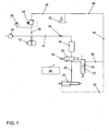
- a preferred embodiment of an injection system according to the invention for an internal combustion engine for example for a diesel engine, comprises a high-pressure pump 10 and a fuel distribution pipe or a rail 12 from which a line 14 with a throttle 16 branches off to an injector or engine cylinder.
- the injector essentially comprises an injector volume 18, a quantity valve 20 in the form of a 2/2-way valve which is driven, for example, by a piezo element or an electromagnet (not shown), a pressure adjusting valve 22 in the form of a 2/3-way valve and an injection nozzle 24, with nozzle needle spring (passive nozzle).
- the injection system includes a rail pressure sensor 26 connected to the fuel rail 12, a pressure regulating valve 28 regulating the pressure in the fuel rail 12, a fuel tank 30, and a drain line 28 connected to the pressure regulating valve 28, the fuel tank 30, the stem pressure adjusting valve 22, and the injector 24.
- Denoted at 34 is an electrical control for the flow control valve 20.
- a fuel line or return line 36 connects the fuel tank 30 to the pressure adjusting valve 22 and via the pressure control valve 28 to the Kraftstoffverteilrohr 12.
- For damping the pressure surges generated by the piston of the high-pressure pump 10 is located; between the rail 12 and the injector memory 18 at least one throttle 16.
- the throttle may be integrated into the injector or into the rail 12.
- the length of the line 14 between the rail 12 and the injector is the same for all cylinders.
- the injector memory 18 is formed generated by a hollow of the injector body.
- the injection quantity release takes place through the 2/2-way valve 20 (flow control valve).
- the 2/3-way valve 22 stabilizes the positive pressure between the injector 24 and the flow control valve 20.
- the leak oil flows, possibly through a radiator (not shown), via the leak oil line 32 and the fuel line 36 back to the fuel tank 30.
- the lines in the injector are as short as possible.
- a first line 40 connects the injector 24 to the flow control valve 20.
- a connection of the pressure adjusting valve 22 is connected to the first line 40.
- the quantity valve is acted upon by a spring 44 in the direction of the closed position with force.
- the 2/3-way valve 22 has three positions, which in addition Fig. 3 to 5 are illustrated.
- a first switching position according to Fig. 3 the 2/3-way valve 22 is closed.
- a second switching position according to Fig. 4 connects the 2/3-way valve 22, the first line 40 to the return line 36 via a formed in the 2/3-way valve 22 throttle 46.
- a third switching position according to Fig. 5 this connection between the first line 40 and the return line 36 is disconnected again.
- the 2/3-way valve 22 is designed such that a pressure applied via the first line 40 in the 2/3-way valve 22 switches between the aforementioned switching positions.
- Fig. 2 a second preferred embodiment of a fuel injection system according to the invention is shown, wherein like reference numerals have functionally identical parts as in Fig. 1 and 3 to 5 so that their explanation in the above description of the Fig. 1 and 3 to 5 is referenced.
- Fig. 1 includes the second embodiment according to Fig. 2 a counter-piston 38 at the injection nozzle 24.
- a space for the opposed piston 38 is connected via a second line 42 to the injector volume 18. This counter-piston 38 exerts an additional closing force on the injection nozzle 24.
- the actuator which actuates the quantity valve 20 is optionally activated in such a way that the quantity valve 20 executes only a partial stroke.
- the injection rate is represented by throttling via the flow control valve 20. Since it is a 2/2-way valve 20, this throttling does not lead to a reduction of the volumetric efficiency.
- a seat throttling in the injection nozzle as provided for example in conventional, known CR (common rail) systems, the mixture forming quality is improved.
- the seat throttling leads to cavitation before and in the nozzle holes and thus to an irregular or uneven distribution of the fuel to the individual injection holes.
- the second embodiment according to Fig. 2 acts a constantly biased by the pressure in the injector memory 18 piston 38 in addition to the back of the nozzle needle 24 a.
- the nozzle opening and closing pressure increases with the rail pressure. This allows an additional degree of freedom in the tuning of the injection system.
- the function corresponds to that of the first embodiment according to FIG Fig. 1 , Like previously described.
- the flow control valve 20 is 100% static pressure balanced to minimize the actuating forces.
- the effective cross section of the flow control valve 20 is, for example 4 times, preferably 4 1/2 times as large as that of the injection nozzle 24, so that no appreciable pressure loss via the flow control valve 20 occurs.
- the 2/3-way valve 22 is in the starting position ( Fig. 3 ) a seat valve.
- the 2nd switch position and the 3rd switch position are sealed via gaps (slide valve), as shown 4 and 5 seen.
- the seat seal in the starting position ( Fig. 3 ) allows a secure holding of the stand pressure, since no leakage occurs over the closed valve 22.
- the passing through the valve 22 amount can be in the embodiment according to Fig. 6 over the length of a plug 48, which releases a throttle cross-section (throttle edge) set. Alternatively, this can be done by adjusting the (transverse) bore diameter in the valve spool.
- FIG. 7 An enlargement of the pressure spread between the first switching positions ( Fig. 3 ) and the third switch position ( Fig. 5 ) can be achieved by placing the seat of the poppet valve on a larger diameter than the pusher diameter, as in Fig. 7 shown.
- the sealing diameter for the initial position (first switching position) is analog Fig. 3 designated.
- the sealing diameter for the third switching position is analog Fig. 5 designated.
- the pressures, and thus the required spring forces behave like the diameters associated surfaces on which is sealed.
- the line pressure acting on the upper face shifts the valve spool.
- the spring force and the spring stiffness, together with the valve travel determine the pressures for the two switching stages.
- the connection of the branch line to the 2/3-way valve 22 is located in the immediate vicinity of the flow control valve 20 to "level" or to absorb the returning pressure wave after closing the injector 24 there.
- the injection quantity is metered directly via the quantity valve 20. This eliminates the errors from the timing chain of a conventional injector.
- a pilot valve is moved via an electromagnet or a piezo actuator. This in turn relieves the back of the injection needle. This lifts off the needle seat and the injection begins.
- the pilot valve is closed, which leads to a pressure build-up on the back of the injection needle and the initiation of the closing movement.
- the pressure wave is effectively calmed, which minimizes the quantity effect on the individual injections.
- the injection quantity corresponds to the amount taken from the reservoir, taking into account the small amount that escapes during pressure build-up and pressure reduction by the 2/3-way valve 22.
- This Abgresmenge is independent of the injection quantity, it is easily influenced by the accumulator pressure.
- the Abberichtmenge is small ( ⁇ 2mm 3 ).
- the operational safety is increased by the 2/3-way valve 22, since small leaks (leaking flow control valve) by shifting the 2/3-way valve 22 in the second switching position ( Fig. 4 ) are intercepted without it comes to a permanent injection.
- the injector memory 18 is dimensioned large and oriented in the direction of the injector needle axis.
- the actuator is roughly oriented in the direction of the injector needle axis (on nozzle).
- the injector memory 18 and the high-pressure port are arranged laterally.
- the present invention can also be used as injector control for the CRID. In this case, the injector memory 18 is replaced by the pressure booster of the CRID.
Landscapes
- Engineering & Computer Science (AREA)
- Chemical & Material Sciences (AREA)
- Combustion & Propulsion (AREA)
- Mechanical Engineering (AREA)
- General Engineering & Computer Science (AREA)
- Fuel-Injection Apparatus (AREA)
Abstract
Die Erfindung betrifft ein Kraftstoffeinspritzsystem für eine Brennkraftmaschine, insbesondere für einen Dieselmotor, mit wenigstens einem Arbeitszylinder und wenigstens einem Injektor pro Arbeitszylinder zum Einspritzen von Kraftstoff in jeweils einen Arbeitszylinder, wobei der Injektor ein Mengenventil (20) und eine mit dem Mengenventil (20) über eine erste Kraftstoffleitung (40) verbundene Einspritzdüse (24) aufweist. Hierbei ist zusätzlich ein Standdruckeinstellventil (22) vorgesehen, welches einerseits mit der ersten Kraftstoffleitung (40) und andererseits mit einem Kraftstoffrücklauf (36) verbunden ist, wobei das Standdruckeinstellventil (22) derart ausgebildet ist, dass dieses unterhalb eines ersten Schaltdruckes in der ersten Kraftstoffleitung (40), welcher kleiner ist als ein Öffnungsdruck der Einspritzdüse (24), in einer ersten Arbeitsstellung den Kraftstoffrücklauf (36) von der Leitung (40) abtrennt, bei dem ersten Schaltdruck und oberhalb des ersten Schaltdruckes sowie unterhalb eines zweiten Schaltdruckes, welcher größer als der erste Schaltdruck und kleiner als der Öffnungsdruck der Einspritzdüse (24) ist, den Kraftstoffrücklauf (36) mit der ersten Kraftstoffleitung (40) in einer zweiten Arbeitsstellung fluidleitend verbindet, sowie bei und oberhalb des zweiten Schaltdruckes in einer dritten Arbeitsstellung den Kraftstoffrücklauf (36) von der ersten Kraftstoffleitung (40) abtrennt.

Description
Die Erfindung betrifft ein Kraftstoffeinspritzsystem für eine Brennkraftmaschine, insbesondere für einen Dieselmotor, mit wenigstens einem Arbeitszylinder und wenigstens einem Injektor pro Arbeitszylinder zum Einspritzen von Kraftstoff in jeweils einen Arbeitszylinder, wobei der Injektor ein Mengenventil und eine mit dem Mengenventil über eine erste Kraftstoffleitung verbundene Einspritzdüse aufweist, gemäß dem Oberbegriff des Patentanspruchs 1.The invention relates to a fuel injection system for an internal combustion engine, in particular for a diesel engine, having at least one working cylinder and at least one injector per cylinder for injecting fuel into each working cylinder, the injector having a quantity valve and an injection nozzle connected to the quantity valve via a first fuel line , according to the preamble of claim 1.
Bekannte Einspritzsysteme weisen eine starke Abhängigkeit der Einspritzmenge von der der vorausgehenden Einspritzung auf, was zu Emissions- und Applikationsproblemen sowie einem reduzierten Wirkungsgrad vor allem bei kleinen Einspritzmengen führt.Known injection systems have a strong dependence of the injection quantity on that of the preceding injection, which leads to emission and application problems as well as a reduced efficiency, especially with small injection quantities.
Der Erfindung liegt die Aufgabe zugrunde, ein Einspritzsystem der o.g. Art hinsichtlich der Absteuermengen und der Strahlaufbereitung zu verbessern und gleichzeitig eine geringere Abhängigkeit der eingespritzten Kraftstoffmenge von der Voreinspritzung zu erzielen.The invention is based on the object, an injection system of o.g. To improve the type of Absteuermengen and the beam conditioning and at the same time to achieve a lower dependence of the injected fuel amount of the pilot injection.
Diese Aufgabe wird erfindungsgemäß durch ein Kraftstoffeinspritzsystem der o.g. Art mit den in Anspruch 1 gekennzeichneten Merkmalen gelöst. Vorteilhafte Ausgestaltungen der Erfindung sind in den weiteren Ansprüchen beschrieben.This object is achieved by a fuel injection system o.g. Art solved with the features characterized in claim 1. Advantageous embodiments of the invention are described in the further claims.
Dazu ist es bei einem Kraftstoffeinspritzsystem der o.g. Art erfindungsgemäß vorgesehen, dass zusätzlich ein Standdruckeinstellventil vorgesehen ist, welches einerseits mit der ersten Kraftstoffleitung und andererseits mit einem Kraftstoffrücklauf verbunden ist, wobei das Standdruckeinstellventil derart ausgebildet ist, dass dieses unterhalb eines ersten Schaltdruckes in der ersten Kraftstoffleitung, welcher kleiner ist als ein Öffnungsdruck der Einspritzdüse, in einer ersten Arbeitsstellung den Kraftstoffrücklauf von der Leitung abtrennt, bei dem ersten Schaltdruck und oberhalb des ersten Schaltdruckes sowie unterhalb eines zweiten Schaltdruckes, welcher größer als der erste Schaltdruck und kleiner als der Öffnungsdruck der Einspritzdüse ist, den Kraftstoffrücklauf mit der ersten Kraftstoffleitung in einer zweiten Arbeitsstellung fluidleitend verbindet, sowie bei und oberhalb des zweiten Schaltdruckes in einer dritten Arbeitsstellung den Kraftstoffrücklauf von der ersten Kraftstoffleitung abtrennt.For this purpose, it is provided according to the invention in a fuel injection system of the type mentioned above, which is additionally connected to the first fuel line and on the other hand with a fuel return, the Standdruckeinstellventil is designed such that this below a first switching pressure in the first fuel line , which is smaller than an opening pressure of the injection nozzle, in a first working position separates the fuel return line, at the first switching pressure and above the first switching pressure and below a second switching pressure which is greater than the first switching pressure and smaller than the opening pressure of the injection nozzle , the fuel return fluidly connects to the first fuel line in a second working position, as well as at and above the second switching pressure in a third working position the fuel return from the first Kr separating off the fuel line.
Dies hat den Vorteil, dass ein Einspritzsystem ohne Separationszeitempfindlichkeit und mit reduzierten Absteuermengen bei besserer Strahlaufbereitung durch den Entfall einer Sitzdrossel zur Verfügung steht. Das erfindungsgemäße Einspritzsystem erzielt einen geringeren Applikationsaufwand, eine verkürzte Baulänge, ein kleineres Kraftstoffverteilrohrvolumen bzw. Railvolumen (Bauraum) und geringere Steuermengen. In der Folge wird weniger Antriebsleitung für die CR(Common Rail)-Pumpe benötigt sowie der Wirkungsgrad verbessert, was auch einen CO2-Vorteil bedingt.This has the advantage that an injection system without Separationszeitempfindlichkeit and with reduced Absteuermengen with better jet preparation by the elimination of a seat throttle is available. The injection system of the invention achieves a lower application cost, a shortened overall length, a smaller Kraftstoffverteilrohrvolumen or rail volume (space) and lower control quantities. As a result, less drive line for the CR (common rail) pump is required and the efficiency improved, which also requires a CO 2 advantage.
Zweckmäßigerweise ist ein mit dem Injektor über eine Leitung verbundenes Kraftstoffverteilerrohr (Common Rail) oder Kraftstoffspeicher und eine mit dem Kraftstoffverteilerrohr verbundene Hochdruckpumpe vorgesehen, wobei der Kraftstoffrücklauf mit einem Kraftstoffstank verbunden ist.Conveniently, a fuel rail connected to the injector via a line (common rail) or fuel storage and a high-pressure pump connected to the fuel rail is provided, wherein the fuel return is connected to a fuel tank.
In einer bevorzugten Ausführungsform ist das Standdruckeinstellventil als 2/3-Wegeventil ausgebildet.In a preferred embodiment, the standard pressure adjustment valve is designed as a 2/3-way valve.
Das Standdruckeinstellventil weist beispielsweise einen axial in Abhängigkeit von dem Druck in der Leitung in die drei Arbeitsstellungen verschiebbaren Kolben auf, welcher in der ersten und der dritten Arbeitsstellung an einer Dichtfläche anschlägt. Hierbei weist das Standdruckeinstellventil bevorzugt ein Federelement auf, welches den Kolben in Richtung der ersten Schaltstellung mit Kraft beaufschlagt.The standard pressure adjusting valve has, for example, an axially displaceable piston depending on the pressure in the line in the three working positions, which abuts in the first and third working position on a sealing surface. Here, the standard pressure adjusting valve preferably has a spring element which acts on the piston in the direction of the first switching position with force.
In einer bevorzugten Ausführungsform ist ein Aktuator für das Mengenventil als Elektromagnet oder Piezoelement oder Magnetorestriktiv ausgebildet.In a preferred embodiment, an actuator for the flow control valve is designed as an electromagnet or piezoelement or magnetostrictive.
Ein kontrolliertes Überströmen von der ersten Kraftstoffleitung in den Kraftstoffrücklauf erzielt man dadurch, dass das Standdruckeinstellventil in der zweiten Arbeitsstellung den Kraftstoffrücklauf mit der ersten Kraftstoffleitung über eine Drossel verbindet.A controlled overflow from the first fuel line into the fuel return is achieved by the fact that the Standdruckeinstellventil connects in the second working position, the fuel return to the first fuel line via a throttle.
In einer alternativen Ausführungsform ist ein Gegenkolben mit einem Druckraum axial zur Einspritzdüse derart vorgesehen, dass der Gegenkolben bei Druck im Druckraum eine axiale Kraft in Richtung der Schließstellung der Einspritzdüse ausübt. Hierbei ist bevorzugt der Druckraum des Gegenkolbens über eine zweite Kraftstoffleitung mit dem Injektorvolumen verbunden.In an alternative embodiment, an opposed piston is provided with a pressure chamber axially to the injection nozzle such that the counter-piston exerts an axial force in the direction of the closed position of the injection nozzle at pressure in the pressure chamber. In this case, the pressure chamber of the counter-piston is preferably connected to the injector volume via a second fuel line.
In einer bevorzugten Ausführungsform ist das Mengenventil als 2/2-Wegeventil ausgebildet.In a preferred embodiment, the quantity valve is designed as a 2/2-way valve.
Zweckmäßigerweise ist in einem Kraftstofftank und/oder im Kraftstoffrücklauf eine Kraftstoffkühlvorrichtung vorgesehen.Conveniently, a fuel cooling device is provided in a fuel tank and / or in the fuel return.
Die Erfindung wird im Folgenden anhand der Zeichnung näher erläutert. Diese zeigt in
- Fig. 1
- ein schematisches Schaltbild einer ersten bevorzugten Ausführungsform eines erfindungsgemäßen Kraftstoffeinspritzsystems,
- Fig. 2
- ein schematisches Schaltbild einer zweiten bevorzugten Ausführungsform eines erfindungsgemäßen Kraftstoffeinspritzsystems,
- Fig. 3
- ein Standdruckeinstellventil in Form eines 2/3-Wegeventils für ein erfindungsgemäßes Kraftstoffeinspritzsystem in schematischer Schnittansicht in einer Ausgangsstellung (erste Sperrstellung),
- Fig. 4
- das Standdruckeinstellventil gemäß
Fig. 3 in Durchflussstellung mit Drossel, - Fig. 5
- das Standdruckeinstellventil gemäß
Fig. 3 in zweiter Sperrstellung, - Fig. 6
- das Standdruckeinstellventil gemäß
Fig. 3 in erster Sperrstellung in vergrößerter Darstellung und - Fig. 7
- eine alternative Ausführungsform des Standdruckeinstellventil in schematischer Schnittansicht.
- Fig. 1
- 1 is a schematic circuit diagram of a first preferred embodiment of a fuel injection system according to the invention,
- Fig. 2
- FIG. 2 is a schematic circuit diagram of a second preferred embodiment of a fuel injection system according to the invention, FIG.
- Fig. 3
- a state pressure adjusting valve in the form of a 2/3-way valve for a fuel injection system according to the invention in a schematic sectional view in an initial position (first blocking position),
- Fig. 4
- the pressure adjusting valve according to
Fig. 3 in flow position with throttle, - Fig. 5
- the pressure adjusting valve according to
Fig. 3 in the second blocking position, - Fig. 6
- the pressure adjusting valve according to
Fig. 3 in the first blocking position in an enlarged view and - Fig. 7
- an alternative embodiment of the standard pressure adjusting valve in a schematic sectional view.
Die in
Das 2/3-Wegeventil 22 weist drei Stellungen auf, die zusätzlich in
In
Nachfolgend wird die Funktionsweise des erfindungsgemäßen Kraftstoffeinspritzsystems anhand der ersten Ausführungsform gemäß der
Erste Einspritzung:
- 1. Vor der Einspritzung:
- a.
Die erste Leitung 40zwischen Mengenventil 20 und Einspritzdüse 24 ist drucklos. Das 2/3-Wegeventil 22 ist geschlossen. Dies ist die Ausgangsstellung des 2/3-Wegeventil 22 gemäßFig. 3 . - b.
Das Mengenventil 20 öffnet aufgrund einer Betätigung durch beispielsweise einen Elektromagneten oder ein Piezoelement (nicht dargestellt). - c. Der Druck in
der Leitung 40zwischen Mengenventil 20 und Einspritzdüse 24 steigt, bis er den Öffnungsdruck (erster Schaltdruck) für die 2. Schaltstufe des 2/3-Wegeventils 22 überschreitet und das 2/3-Wegeventils 22 wechselt zur 2. Schaltstellung "Durchfluss mit Drossel 46" (Fig. 4 ). , - d. Kraftstoff strömt über die
Drossel 46 des 2/3-Wegeventils 22, wie inFig. 4 dargestellt, inden Rücklauf 36zum Kraftstofftank 30. Der Druck für die 2. Schaltstufe des 2/3-Wegeventils 22 liegt unter dem Öffnungsdruck der Einspritzdüse 24. - e. Der Druck in
der Leitung 40zwischen Mengenventil 20 und Einspritzdüse 24 steigt weiter. Das 2/3-Wegeventil 22 wechselt bei Überschreiten eines vorbestimmten zweiten Schaltdruckes in der ersten Leitung 40 in die 3. Schaltstufe "zweite Sperrstellung" (Fig. 5 ). Es sperrt den Durchfluss indie Rücklaufleitung 36 erneut ab. Dieser zweite Schaltdruck ist bevorzugt etwas kleiner als der Öffnungsdruck der Einspritzdüse 24.
- a.
- 2. Einspritzung:
- a. Der weiterhin durch
das Mengenventil 20 tretende Kraftstoff hebt den Druck inder Leitung 40zwischen Mengenventil 20 und Einspritzdüse 24 so weit an, dass der Öffnungsdruck der Einspritzdüse 24 überschritten wird und dementsprechend die Einspritzung beginnt. - b. Da der freie Querschnitt des Mengenventils 20 deutlich größer (ca. 4-5 mal) als der der Einspritzdüse 24 ist, tritt keine merkliche Drosselung über
das Mengenventil 20 auf. Der Druckverlust ist beispielsweise kleiner als 5% des Druckes indem Rail 12. - c.
Die federbelastete Einspritzdüse 24 "schnappt" auf, d.h. kaum Nadeldrosselung. Die Nadel schaltet quasi digital von zu nach auf.
- a. Der weiterhin durch
- 3. Einspritzende:
- a.
Das Mengenventil 20 wird durch dieFeder 44 geschlossen. Der Druck inder Leitung 40zwischen Mengenventil 20 und Einspritzdüse 24 fällt sehr schnell ab. - b.
Die Einspritzdüse 24 schließt, sobald ein Schließbeginndruck erreicht bzw. unterschritten wird. - c. Das 2/3-
Wegeventil 22 bewegt sich in die Mittelstellung (Fig. 4 ). Über dieDrossel 46 in dem 2/3-Wegeventil 22 fließt zusätzlich Kraftstoff aus der Leitung 40 inden Rücklauf 36 ab, so dass der Druckabfall in der Leitung 49 beschleunigt wird. - d.
Die Einspritzdüse 24 schließt, wobei aufgrund des schnellen Druckabfalls in der ersten Leitung 40 während der Schließphase wenig Kraftstoff austritt. Daraus folgt eine gute Zerstäubung ohne Sitzdrosselung (siehe auch SAE 2003-01-0698).Die zum Mengenventil 20 rücklaufende Druckwelle aufgrund des Schließens der Einspritzdüse 24 wird über dieDrossel 46 in dem 2/3-Wegeventil 22 abgebaut. Ein Nachspritzen der Einspritzdüse 24 wird dadurch funktionssicher vermieden. - e. Sobald der Standdruck (erster Schaltdruck) in
der Leitung 40zwischen Mengenventil 20 und Einspritzdüse 24 erreicht wird, schließt das 2/3-Wegeventil 22 und es bewegt sich in die Grundstellung zurück (Fig. 3 ). Der Standdruck bleibt erhalten.
- a.
- 4. Folgende Einspritzungen:
Wie oben, wobei jedoch dieLeitung 40 bereits unter Standdruck steht und nicht mehr so weit vorgespannt werden muss. DasÖffnen des Mengenventils 20 bewirkt sofort ein Überschreiten des ersten Schaltdruckes in derLeitung 40 und dementsprechend ein Schalten des 2/3-Wegeventils 22 in die 2. Schaltstufe. Der restliche Ablauf wie unter Punkten 3. und 4 oben ist analog. Der Standdruck verhindert Kavitation und ein unbekanntes "Luftvolumen" in der Leitung. Weiterhin ergibt sich ein Wirkungsgradvorteil durch vorweggenommene Kraftstoffkompressibilität.
- 1. Before the injection:
- a. The
first line 40 betweenflow control valve 20 andinjector 24 is depressurized. The 2/3-way valve 22 is closed. This is the starting position of the 2/3-way valve 22 according toFig. 3 , - b. The
flow control valve 20 opens due to actuation by, for example, an electromagnet or a piezoelectric element (not shown). - c. The pressure in the
line 40 betweenflow control valve 20 andinjector 24 increases until it exceeds the opening pressure (first switching pressure) for the 2nd switching stage of the 2/3-way valve 22 and the 2/3-way valve 22 changes to the second switching position "flow withthrottle 46 "(Fig. 4 ). . - d. Fuel flows via the
throttle 46 of the 2/3-way valve 22, as inFig. 4 shown, in thereturn line 36 to thefuel tank 30. The pressure for the 2nd switching stage of the 2/3-way valve 22 is below the opening pressure of the injection nozzle 24th - e. The pressure in
line 40 betweenflow control valve 20 andinjector 24 continues to increase. The 2/3-way valve 22 changes when a predetermined second switching pressure in thefirst line 40 in the third switching stage "second Lock position "(Fig. 5 ). It blocks the flow in thereturn line 36 again. This second switching pressure is preferably slightly smaller than the opening pressure of theinjection nozzle 24.
- a. The
- 2nd injection:
- a. The further passing through the
flow control valve 20 fuel raises the pressure in theline 40 betweenflow control valve 20 andinjector 24 so far that the opening pressure of theinjector 24 is exceeded and, accordingly, the injection begins. - b. Since the free cross section of the
flow control valve 20 is significantly larger (about 4-5 times) than that of theinjection nozzle 24, no appreciable throttling occurs via theflow control valve 20. For example, the pressure loss is less than 5% of the pressure in therail 12. - c. The spring-loaded
injector 24 "snaps" on, ie hardly needle throttling. The needle switches from digital to digital.
- a. The further passing through the
- 3rd injection end:
- a. The
flow control valve 20 is closed by thespring 44. The pressure in theline 40 betweenflow control valve 20 andinjector 24 drops very quickly. - b. The
injection nozzle 24 closes as soon as a closing start pressure is reached or fallen below. - c. The 2/3-
way valve 22 moves to the middle position (Fig. 4 ). In addition, fuel flows from theline 40 into thereturn line 36 via thethrottle 46 in the 2/3-way valve 22, so that the pressure drop in the line 49 is accelerated. - d. The
injector 24 closes, leaving little fuel due to the rapid pressure drop in thefirst conduit 40 during the closing phase. This results in a good atomization without seat throttling (see also SAE 2003-01-0698). The return to theflow valve 20 pressure wave due to the closing of theinjector 24 is reduced via thethrottle 46 in the 2/3-way valve 22. Injection of theinjection nozzle 24 is thereby reliably avoided. - e. As soon as the stand pressure (first switching pressure) in the
line 40 between thequantity valve 20 and theinjection nozzle 24 is reached, the 2/3-way valve 22 closes and it moves back into the normal position (FIG.Fig. 3 ). The pressure remains.
- a. The
- 4. Following injections:
As above, but theline 40 is already under pressure and no longer has to be biased so far. The opening of thequantity valve 20 immediately causes an exceeding the first switching pressure in theline 40 and, accordingly, a switching of the 2/3-way valve 22 in the second switching stage. The rest of the procedure as under points 3 and 4 above is analog. The stand pressure prevents cavitation and an unknown "air volume" in the pipe. Furthermore, there is an efficiency advantage through anticipated fuel compressibility.
Um Einfluss auf den Einspritzverlauf zu nehmen bzw. die Dosierfähigkeit bei Kleinstmengen zu verbessern, wird der Aktuator, der das Mengenventil 20 betätigt, optional derart angesteuert, dass das Mengenventil 20 lediglich einen Teilhub ausführt. Die Einspritzrate wird durch Drosselung über das Mengenventil 20 dargestellt. Da es sich um ein 2/2-Wegeventil 20 handelt führt diese Drosselung nicht zu einer Reduktion des volumetrischen Wirkungsgrades. Gegenüber einer Sitzdrosselung in der Einspritzdüse, wie beispielsweise bei herkömmlichen, bekannten CR(Common Rail)-Systemen vorgesehen, ist die Gemischbildungsgüte verbessert. Die Sitzdrosselung führt zu Kavitation vor und in den Düsenlöchern und damit zu einer unregelmäßigen bzw. ungleichmäßigen Verteilung des Kraftstoffes auf die einzelnen Einspritzlöcher.In order to influence the course of injection or to improve the metering capability for very small quantities, the actuator which actuates the
Bei der zweiten Ausführungsform gemäß
Das Mengenventil 20 ist zu 100% statisch druckausgeglichen, um die Betätigungskräfte zu minimieren. Zusätzlich ist das Mengenventil 20 größtenteils dynamisch druckausgeglichen ausgebildet..Der effektive Querschnitt des Mengenventils 20 ist beispielsweise 4 mal, bevorzugt 4 1/2-mal so groß wie der der Einspritzdüse 24, damit kein merklicher Druckverlust über das Mengenventil 20 auftritt. Das 2/3-Wegeventil 22 ist in der Ausgangstellung (
Eine Vergrößerung der Druckspreizung zwischen den ersten Schaltstellungen (
Es ergibt sich eine geringere Mengenstreuung durch direkte Freigabe der Einspritzmenge. Die Einspritzmenge wird direkt über das Mengenventil 20 dosiert. Damit entfallen die Fehler aus der Steuerkette eines üblichen Injektors. Bei diesen wird über einen Elektromagneten oder einen Piezoaktuator ein Vorsteuerventil bewegt. Dieses wiederum entlastet die Rückseite der Einspritznadel. Diese hebt vom Nadelsitz ab und die Einspritzung beginnt. Um die Einspritzung zu beenden wird das Vorsteuerventil geschlossen, was zu einem Druckaufbau auf der Rückseite der Einspritznadel und zur Initiation der Schließbewegung führt.This results in a smaller amount of scatter by direct release of the injection quantity. The injection quantity is metered directly via the
Nachfolgend wird die Dämpfung bzw. Verhinderung der Druckwellenwirkung auf die Einspritzmenge näher erläutert. Die meist mit 2/2-Wegeventilen durchgeführte, Vorsteuerung führt dazu, dass die Absteuermenge bedeutsam wird. Bei kleinen Einspritzmengen, beispielsweise Voreinspritzungen von 1 mg, beträgt die Absteuermenge ein Mehrfaches der Einspritzmenge. Die Absteuermenge wird, genau wie die Einspritzmenge, dem Injektor und damit der Kraftstoffverteilleiste entzogen. Dieser Mengenverlust löst eine starke Druckwelle aus. Diese Druckwelle führt ihrerseits zum Effekt der sich verändernden Einspritzmenge in Abhängigkeit des Abstandes zwischen zwei Einspritzungen. Um die Wirkung der Druckwellen zu minimieren werden bei der vorliegenden Erfindung folgende Maßnahmen ergriffen:
- 1. Die gesamte dem System entzogenen Menge (Absteuer- und Einspritzmenge) ist minimiert, da damit die Anregung der Druckwellen minimiert wird.
- 2. Die Leitungslänge zwischen dem Mengenventil bzw.
Vorsteuerventil 20 ist minimiert, damit die Störung möglichst hochfrequent ist. Je größer die Frequenz der Schwingung, desto größer wird die Dämpfung, d.h. die Zeit, nach der die Störung abgeklungen ist, verkürzt sich. - 3. Die Druckwelle wird nah am Entstehungspunkt gedämpft. Die Dämpfung erfolgt bei dem erfindungsgemäßen Kraftstoffeinspritzsystem durch die kombinierte Anwendung eines Volumens (Injektorspeicher 18) und der
Drossel 46.
- 1. The total amount withdrawn from the system (spill and injection quantity) is minimized because it minimizes the excitation of the pressure waves.
- 2. The line length between the quantity valve or
pilot valve 20 is minimized, so that the disturbance is as high as possible. The greater the frequency of the oscillation, the greater the attenuation, ie the time after which the disturbance has subsided, is shortened. - 3. The pressure wave is damped close to the point of origin. The damping takes place in the fuel injection system according to the invention by the combined use of a volume (injector memory 18) and the throttle 46th
Durch die Kombination der drei vorgenannten Maßnahmen wird die Druckwelle wirksam beruhigt, was den Mengeneffekt auf die einzelnen Einspritzungen minimiert.By combining the three aforementioned measures, the pressure wave is effectively calmed, which minimizes the quantity effect on the individual injections.
Weiterhin ergeben sich Wirkungsgradvorteile, d.h. geringere Absteuermengen. Die Einspritzmenge entspricht der aus dem Speicher entnommenen Menge unter Berücksichtigung der kleinen Menge die beim Druckaufbau und Druckabbau durch das 2/3-Wegeventil 22 entweicht. Diese Absteuermenge ist unabhängig von der Einspritzmenge, sie wird leicht durch den Speicherdruck beeinflusst. Die Absteuermenge ist klein (<2mm3).Furthermore, there are efficiency advantages, ie lower Absteuermengen. The injection quantity corresponds to the amount taken from the reservoir, taking into account the small amount that escapes during pressure build-up and pressure reduction by the 2/3-
Die Betriebsicherheit wird durch das 2/3-Wegeventil 22 gesteigert, da kleine Leckagen (undichtes Mengenventil) durch verschieben des 2/3-Wegeventils 22 in die zweite Schaltstellung (
Durch eine Weg-/Geschwindigkeitsmessung der Nadel des 2/3-Wegeventils 22 und/oder der Düsennadel 24 kann eine für die OBD verwertbare Rückmeldung über den Zustand des Einspritzsystems erzeugt werden:
- a. Innere Leckage über 2/3-Wegeventil
- b. Einspritzdauer bzw. Spritzverzug über Düsennadel bzw. 2/3-Wegeventilsensierung
- a. Internal leakage via 2/3-way valve
- b. Injection time or spraying delay via nozzle needle or 2/3-way valve sensing
Es wird weiterhin eine Baulänge sparende Bauweise insbesondere für 2-V-Motoren (Schrägeinbau) und MSV-Konzepte (MSV = Mehrstufenverbrennung) erzielt mit einer Länge < 130mm bzw. < 100mm. Der Injektorspeicher 18 ist groß dimensioniert und in Richtung der Einspritzdüsennadelachse orientiert. Der Aktuator ist grob in Richtung der Einspritzdüsennadelachse orientiert (auf Düse). Der Injektorspeicher 18 und der Hochdruckanschluss sind seitlich angeordnet. Die vorliegende Erfindung ist auch als Einspritzventilsteuerung für den CRID einsetzbar. In diesem Fall kommt an die Stelle des Injektorspeichers 18 der Druckverstärker des CRID.It is further achieved with a length of <130 mm and <100 mm, a length-saving design and in particular for 2-V-engines (inclined installation) and MSV concepts (MSV = M o s v tufen erbrennung). The
- 1010
- Hochdruckpumpehigh pressure pump
- 1212
- Kraftstoffverteilrohr bzw. ein RailFuel distribution pipe or a rail
- 1414
- Leitungmanagement
- 1616
- Drosselthrottle
- 1818
- Injektorvolumeninjector volume
- 2020
- Mengenventil / 2/2-WegeventilQuantity valve / 2/2-way valve
- 2222
- Standdruckeinstellventil / 3/2-WegeventilPressure adjusting valve / 3/2-way valve
- 2424
- Einspritzdüseinjection
- 2626
- RaildrucksensorRail pressure sensor
- 2828
- DruckregelventilPressure control valve
- 3030
- KraftstofftankFuel tank
- 3232
- LeckölleitungDrain line
- 3434
-
Steuerung für das Mengenventil 20Control for the
quantity valve 20 - 3636
- Kraftstoffleitung / RücklaufleitungFuel line / return line
- 3838
- Gegenkolbenopposed piston
- 4040
- erste Kraftstoffleitungfirst fuel line
- 4242
- zweite Kraftstoffleitungsecond fuel line
- 4444
- Federfeather
- 4646
-
Drossel in 2/3-Wegeventil 22Throttle in 2/3-
way valve 22 - 4848
- StopfenPlug
- 5050
- Dichtdurchmesser für die Ausgangsstellung (erste Schaltstellung)Sealing diameter for the initial position (first switching position)
- 5252
- Dichtdurchmesser für die dritte SchaltstellungSealing diameter for the third switching position
Claims (12)
Applications Claiming Priority (1)
| Application Number | Priority Date | Filing Date | Title |
|---|---|---|---|
| DE200810015857 DE102008015857A1 (en) | 2008-03-27 | 2008-03-27 | Fuel injection system for an internal combustion engine |
Publications (3)
| Publication Number | Publication Date |
|---|---|
| EP2105604A2 true EP2105604A2 (en) | 2009-09-30 |
| EP2105604A3 EP2105604A3 (en) | 2010-11-17 |
| EP2105604B1 EP2105604B1 (en) | 2013-04-10 |
Family
ID=40810086
Family Applications (1)
| Application Number | Title | Priority Date | Filing Date |
|---|---|---|---|
| EP09001412.7A Not-in-force EP2105604B1 (en) | 2008-03-27 | 2009-02-02 | Fuel injection system for a combustion engine |
Country Status (2)
| Country | Link |
|---|---|
| EP (1) | EP2105604B1 (en) |
| DE (1) | DE102008015857A1 (en) |
Families Citing this family (1)
| Publication number | Priority date | Publication date | Assignee | Title |
|---|---|---|---|---|
| DE102014210779A1 (en) | 2014-06-05 | 2015-12-17 | Volkswagen Aktiengesellschaft | Fuel injector |
Family Cites Families (6)
| Publication number | Priority date | Publication date | Assignee | Title |
|---|---|---|---|---|
| DE3009750C2 (en) * | 1980-03-14 | 1987-01-02 | M.A.N.- B & W Diesel GmbH, 8900 Augsburg | Fuel injection device for internal combustion engines |
| AT2961U3 (en) * | 1998-07-02 | 1999-11-25 | Avl List Gmbh | STORAGE INJECTION DEVICE |
| GB9822653D0 (en) * | 1998-10-17 | 1998-12-09 | Lucas Ind Plc | Fuel system |
| DE10033428C2 (en) * | 2000-07-10 | 2002-07-11 | Bosch Gmbh Robert | Pressure controlled injector for injecting fuel |
| DE10046662B4 (en) * | 2000-09-20 | 2004-09-30 | Robert Bosch Gmbh | Fuel injection valve with a pressure control valve |
| DE10330132A1 (en) * | 2003-07-04 | 2005-01-20 | Robert Bosch Gmbh | Pressure holding valve for fuel injection system, comprises release mechanism located in the valve housing between the first connection and the valve head |
-
2008
- 2008-03-27 DE DE200810015857 patent/DE102008015857A1/en not_active Withdrawn
-
2009
- 2009-02-02 EP EP09001412.7A patent/EP2105604B1/en not_active Not-in-force
Non-Patent Citations (1)
| Title |
|---|
| None |
Also Published As
| Publication number | Publication date |
|---|---|
| EP2105604B1 (en) | 2013-04-10 |
| DE102008015857A1 (en) | 2009-10-01 |
| EP2105604A3 (en) | 2010-11-17 |
Similar Documents
| Publication | Publication Date | Title |
|---|---|---|
| EP1654456B1 (en) | Fuel injection device for an internal combustion engine | |
| EP1125046B1 (en) | Fuel injection system for an internal combustion engine with a pressure amplifier | |
| DE10024268B4 (en) | Device for gasoline direct injection in a reciprocating internal combustion engine | |
| EP1392966A1 (en) | Fuel injection device with pressure amplification device and pressure amplification device | |
| WO2001088365A1 (en) | Injection assembly for an accumulator fuel-injection system of an internal combustion engine | |
| DE102004053421A1 (en) | Fuel injector | |
| WO2004003376A1 (en) | Boosted fuel injector with rapid pressure reduction at end of injection | |
| EP1925812B1 (en) | Fuel injector valve for combustion engines | |
| EP1187984B1 (en) | Control valve and fuel injection valve provided with a control valve of this type | |
| EP2835526B1 (en) | Valve assembly for a fuel supply system and fuel supply system | |
| EP2156050B1 (en) | Pressure boosting system for at least one fuel injector | |
| DE19640085C1 (en) | Stop valve to limit the flow rate | |
| EP2105604B1 (en) | Fuel injection system for a combustion engine | |
| DE102018200565A1 (en) | Injector for metering gaseous fuel, Gaseinblassystem with such an injector and method for operating this injector | |
| DE19945785A1 (en) | Fuel injection system for internal combustion engines and method for injecting fuel into the combustion chamber of an internal combustion engine | |
| DE102015226070A1 (en) | fuel injector | |
| DE102007005382A1 (en) | Injector i.e. common rail injector, for injecting fuel e.g. diesel, into combustion chamber of internal-combustion engine, has control valve for varying control pressure, and fuel tank connected with nozzle chamber via throttle channel | |
| DE10132248C2 (en) | Fuel injector with 2-way valve control | |
| DE10357873A1 (en) | Injector | |
| EP1920156B1 (en) | Fuel injection system for an internal combustion engine | |
| DE102006026877A1 (en) | Fuel injection device for an internal combustion engine | |
| EP1313945B1 (en) | Injection valve for the injection of fuel in an internal combustion engine and method for control of the opening and closing process of a nozzle needle in an injection valve | |
| DE102007001365A1 (en) | Common rail injector, for injecting e.g. petrol, into combustion chamber of internal combustion engine, has switching chamber connected with low pressure area by connecting channel that is closed and opened by control valve | |
| DE10300385B3 (en) | Fuel injection device for internal combustion engine has 3/3-way valve using high pressure e.g. common-rail pressure, for rapid valve closure | |
| DE102004028886A1 (en) | Fuel injection system |
Legal Events
| Date | Code | Title | Description |
|---|---|---|---|
| PUAI | Public reference made under article 153(3) epc to a published international application that has entered the european phase |
Free format text: ORIGINAL CODE: 0009012 |
|
| AK | Designated contracting states |
Kind code of ref document: A2 Designated state(s): AT BE BG CH CY CZ DE DK EE ES FI FR GB GR HR HU IE IS IT LI LT LU LV MC MK MT NL NO PL PT RO SE SI SK TR |
|
| AX | Request for extension of the european patent |
Extension state: AL BA RS |
|
| PUAL | Search report despatched |
Free format text: ORIGINAL CODE: 0009013 |
|
| AK | Designated contracting states |
Kind code of ref document: A3 Designated state(s): AT BE BG CH CY CZ DE DK EE ES FI FR GB GR HR HU IE IS IT LI LT LU LV MC MK MT NL NO PL PT RO SE SI SK TR |
|
| AX | Request for extension of the european patent |
Extension state: AL BA RS |
|
| RIC1 | Information provided on ipc code assigned before grant |
Ipc: F02M 63/00 20060101AFI20101012BHEP Ipc: F02M 61/20 20060101ALI20101012BHEP Ipc: F02M 63/02 20060101ALI20101012BHEP |
|
| 17P | Request for examination filed |
Effective date: 20110517 |
|
| AKX | Designation fees paid |
Designated state(s): AT BE BG CH CY CZ DE DK EE ES FI FR GB GR HR HU IE IS IT LI LT LU LV MC MK MT NL NO PL PT RO SE SI SK TR |
|
| RIC1 | Information provided on ipc code assigned before grant |
Ipc: F02M 63/02 20060101ALI20120126BHEP Ipc: F02M 63/00 20060101AFI20120126BHEP Ipc: F02M 61/20 20060101ALI20120126BHEP Ipc: F02M 37/00 20060101ALI20120126BHEP |
|
| 17Q | First examination report despatched |
Effective date: 20120427 |
|
| RAP1 | Party data changed (applicant data changed or rights of an application transferred) |
Owner name: VOLKSWAGEN AKTIENGESELLSCHAFT |
|
| GRAP | Despatch of communication of intention to grant a patent |
Free format text: ORIGINAL CODE: EPIDOSNIGR1 |
|
| GRAS | Grant fee paid |
Free format text: ORIGINAL CODE: EPIDOSNIGR3 |
|
| GRAA | (expected) grant |
Free format text: ORIGINAL CODE: 0009210 |
|
| AK | Designated contracting states |
Kind code of ref document: B1 Designated state(s): AT BE BG CH CY CZ DE DK EE ES FI FR GB GR HR HU IE IS IT LI LT LU LV MC MK MT NL NO PL PT RO SE SI SK TR |
|
| REG | Reference to a national code |
Ref country code: GB Ref legal event code: FG4D Free format text: NOT ENGLISH |
|
| REG | Reference to a national code |
Ref country code: AT Ref legal event code: REF Ref document number: 606156 Country of ref document: AT Kind code of ref document: T Effective date: 20130415 Ref country code: CH Ref legal event code: EP |
|
| REG | Reference to a national code |
Ref country code: IE Ref legal event code: FG4D Free format text: LANGUAGE OF EP DOCUMENT: GERMAN |
|
| REG | Reference to a national code |
Ref country code: DE Ref legal event code: R096 Ref document number: 502009006761 Country of ref document: DE Effective date: 20130606 |
|
| PG25 | Lapsed in a contracting state [announced via postgrant information from national office to epo] |
Ref country code: SI Free format text: LAPSE BECAUSE OF FAILURE TO SUBMIT A TRANSLATION OF THE DESCRIPTION OR TO PAY THE FEE WITHIN THE PRESCRIBED TIME-LIMIT Effective date: 20130410 |
|
| REG | Reference to a national code |
Ref country code: LT Ref legal event code: MG4D Ref country code: NL Ref legal event code: VDEP Effective date: 20130410 |
|
| PG25 | Lapsed in a contracting state [announced via postgrant information from national office to epo] |
Ref country code: ES Free format text: LAPSE BECAUSE OF FAILURE TO SUBMIT A TRANSLATION OF THE DESCRIPTION OR TO PAY THE FEE WITHIN THE PRESCRIBED TIME-LIMIT Effective date: 20130721 Ref country code: PT Free format text: LAPSE BECAUSE OF FAILURE TO SUBMIT A TRANSLATION OF THE DESCRIPTION OR TO PAY THE FEE WITHIN THE PRESCRIBED TIME-LIMIT Effective date: 20130812 Ref country code: LT Free format text: LAPSE BECAUSE OF FAILURE TO SUBMIT A TRANSLATION OF THE DESCRIPTION OR TO PAY THE FEE WITHIN THE PRESCRIBED TIME-LIMIT Effective date: 20130410 Ref country code: NL Free format text: LAPSE BECAUSE OF FAILURE TO SUBMIT A TRANSLATION OF THE DESCRIPTION OR TO PAY THE FEE WITHIN THE PRESCRIBED TIME-LIMIT Effective date: 20130410 Ref country code: FI Free format text: LAPSE BECAUSE OF FAILURE TO SUBMIT A TRANSLATION OF THE DESCRIPTION OR TO PAY THE FEE WITHIN THE PRESCRIBED TIME-LIMIT Effective date: 20130410 Ref country code: NO Free format text: LAPSE BECAUSE OF FAILURE TO SUBMIT A TRANSLATION OF THE DESCRIPTION OR TO PAY THE FEE WITHIN THE PRESCRIBED TIME-LIMIT Effective date: 20130710 Ref country code: GR Free format text: LAPSE BECAUSE OF FAILURE TO SUBMIT A TRANSLATION OF THE DESCRIPTION OR TO PAY THE FEE WITHIN THE PRESCRIBED TIME-LIMIT Effective date: 20130711 Ref country code: IS Free format text: LAPSE BECAUSE OF FAILURE TO SUBMIT A TRANSLATION OF THE DESCRIPTION OR TO PAY THE FEE WITHIN THE PRESCRIBED TIME-LIMIT Effective date: 20130810 Ref country code: SE Free format text: LAPSE BECAUSE OF FAILURE TO SUBMIT A TRANSLATION OF THE DESCRIPTION OR TO PAY THE FEE WITHIN THE PRESCRIBED TIME-LIMIT Effective date: 20130410 |
|
| PG25 | Lapsed in a contracting state [announced via postgrant information from national office to epo] |
Ref country code: LV Free format text: LAPSE BECAUSE OF FAILURE TO SUBMIT A TRANSLATION OF THE DESCRIPTION OR TO PAY THE FEE WITHIN THE PRESCRIBED TIME-LIMIT Effective date: 20130410 Ref country code: PL Free format text: LAPSE BECAUSE OF FAILURE TO SUBMIT A TRANSLATION OF THE DESCRIPTION OR TO PAY THE FEE WITHIN THE PRESCRIBED TIME-LIMIT Effective date: 20130410 Ref country code: BG Free format text: LAPSE BECAUSE OF FAILURE TO SUBMIT A TRANSLATION OF THE DESCRIPTION OR TO PAY THE FEE WITHIN THE PRESCRIBED TIME-LIMIT Effective date: 20130710 Ref country code: HR Free format text: LAPSE BECAUSE OF FAILURE TO SUBMIT A TRANSLATION OF THE DESCRIPTION OR TO PAY THE FEE WITHIN THE PRESCRIBED TIME-LIMIT Effective date: 20130410 Ref country code: CY Free format text: LAPSE BECAUSE OF FAILURE TO SUBMIT A TRANSLATION OF THE DESCRIPTION OR TO PAY THE FEE WITHIN THE PRESCRIBED TIME-LIMIT Effective date: 20130410 |
|
| PG25 | Lapsed in a contracting state [announced via postgrant information from national office to epo] |
Ref country code: EE Free format text: LAPSE BECAUSE OF FAILURE TO SUBMIT A TRANSLATION OF THE DESCRIPTION OR TO PAY THE FEE WITHIN THE PRESCRIBED TIME-LIMIT Effective date: 20130410 Ref country code: CZ Free format text: LAPSE BECAUSE OF FAILURE TO SUBMIT A TRANSLATION OF THE DESCRIPTION OR TO PAY THE FEE WITHIN THE PRESCRIBED TIME-LIMIT Effective date: 20130410 Ref country code: SK Free format text: LAPSE BECAUSE OF FAILURE TO SUBMIT A TRANSLATION OF THE DESCRIPTION OR TO PAY THE FEE WITHIN THE PRESCRIBED TIME-LIMIT Effective date: 20130410 Ref country code: DK Free format text: LAPSE BECAUSE OF FAILURE TO SUBMIT A TRANSLATION OF THE DESCRIPTION OR TO PAY THE FEE WITHIN THE PRESCRIBED TIME-LIMIT Effective date: 20130410 |
|
| PLBE | No opposition filed within time limit |
Free format text: ORIGINAL CODE: 0009261 |
|
| STAA | Information on the status of an ep patent application or granted ep patent |
Free format text: STATUS: NO OPPOSITION FILED WITHIN TIME LIMIT |
|
| PG25 | Lapsed in a contracting state [announced via postgrant information from national office to epo] |
Ref country code: RO Free format text: LAPSE BECAUSE OF FAILURE TO SUBMIT A TRANSLATION OF THE DESCRIPTION OR TO PAY THE FEE WITHIN THE PRESCRIBED TIME-LIMIT Effective date: 20130410 Ref country code: IT Free format text: LAPSE BECAUSE OF FAILURE TO SUBMIT A TRANSLATION OF THE DESCRIPTION OR TO PAY THE FEE WITHIN THE PRESCRIBED TIME-LIMIT Effective date: 20130410 |
|
| 26N | No opposition filed |
Effective date: 20140113 |
|
| REG | Reference to a national code |
Ref country code: DE Ref legal event code: R097 Ref document number: 502009006761 Country of ref document: DE Effective date: 20140113 |
|
| BERE | Be: lapsed |
Owner name: VOLKSWAGEN A.G. Effective date: 20140228 |
|
| PG25 | Lapsed in a contracting state [announced via postgrant information from national office to epo] |
Ref country code: LU Free format text: LAPSE BECAUSE OF FAILURE TO SUBMIT A TRANSLATION OF THE DESCRIPTION OR TO PAY THE FEE WITHIN THE PRESCRIBED TIME-LIMIT Effective date: 20140202 Ref country code: MC Free format text: LAPSE BECAUSE OF FAILURE TO SUBMIT A TRANSLATION OF THE DESCRIPTION OR TO PAY THE FEE WITHIN THE PRESCRIBED TIME-LIMIT Effective date: 20130410 |
|
| REG | Reference to a national code |
Ref country code: CH Ref legal event code: PL |
|
| PG25 | Lapsed in a contracting state [announced via postgrant information from national office to epo] |
Ref country code: LI Free format text: LAPSE BECAUSE OF NON-PAYMENT OF DUE FEES Effective date: 20140228 Ref country code: CH Free format text: LAPSE BECAUSE OF NON-PAYMENT OF DUE FEES Effective date: 20140228 |
|
| REG | Reference to a national code |
Ref country code: IE Ref legal event code: MM4A |
|
| PG25 | Lapsed in a contracting state [announced via postgrant information from national office to epo] |
Ref country code: BE Free format text: LAPSE BECAUSE OF NON-PAYMENT OF DUE FEES Effective date: 20140228 Ref country code: IE Free format text: LAPSE BECAUSE OF NON-PAYMENT OF DUE FEES Effective date: 20140202 |
|
| REG | Reference to a national code |
Ref country code: FR Ref legal event code: PLFP Year of fee payment: 7 |
|
| REG | Reference to a national code |
Ref country code: AT Ref legal event code: MM01 Ref document number: 606156 Country of ref document: AT Kind code of ref document: T Effective date: 20140202 |
|
| PGFP | Annual fee paid to national office [announced via postgrant information from national office to epo] |
Ref country code: DE Payment date: 20150228 Year of fee payment: 7 |
|
| PG25 | Lapsed in a contracting state [announced via postgrant information from national office to epo] |
Ref country code: AT Free format text: LAPSE BECAUSE OF NON-PAYMENT OF DUE FEES Effective date: 20140202 |
|
| PGFP | Annual fee paid to national office [announced via postgrant information from national office to epo] |
Ref country code: GB Payment date: 20150227 Year of fee payment: 7 Ref country code: FR Payment date: 20150227 Year of fee payment: 7 |
|
| PG25 | Lapsed in a contracting state [announced via postgrant information from national office to epo] |
Ref country code: MT Free format text: LAPSE BECAUSE OF FAILURE TO SUBMIT A TRANSLATION OF THE DESCRIPTION OR TO PAY THE FEE WITHIN THE PRESCRIBED TIME-LIMIT Effective date: 20130410 |
|
| PG25 | Lapsed in a contracting state [announced via postgrant information from national office to epo] |
Ref country code: TR Free format text: LAPSE BECAUSE OF FAILURE TO SUBMIT A TRANSLATION OF THE DESCRIPTION OR TO PAY THE FEE WITHIN THE PRESCRIBED TIME-LIMIT Effective date: 20130410 Ref country code: HU Free format text: LAPSE BECAUSE OF FAILURE TO SUBMIT A TRANSLATION OF THE DESCRIPTION OR TO PAY THE FEE WITHIN THE PRESCRIBED TIME-LIMIT; INVALID AB INITIO Effective date: 20090202 |
|
| REG | Reference to a national code |
Ref country code: DE Ref legal event code: R119 Ref document number: 502009006761 Country of ref document: DE |
|
| GBPC | Gb: european patent ceased through non-payment of renewal fee |
Effective date: 20160202 |
|
| REG | Reference to a national code |
Ref country code: FR Ref legal event code: ST Effective date: 20161028 |
|
| PG25 | Lapsed in a contracting state [announced via postgrant information from national office to epo] |
Ref country code: DE Free format text: LAPSE BECAUSE OF NON-PAYMENT OF DUE FEES Effective date: 20160901 Ref country code: FR Free format text: LAPSE BECAUSE OF NON-PAYMENT OF DUE FEES Effective date: 20160229 Ref country code: GB Free format text: LAPSE BECAUSE OF NON-PAYMENT OF DUE FEES Effective date: 20160202 |
|
| PG25 | Lapsed in a contracting state [announced via postgrant information from national office to epo] |
Ref country code: MK Free format text: LAPSE BECAUSE OF FAILURE TO SUBMIT A TRANSLATION OF THE DESCRIPTION OR TO PAY THE FEE WITHIN THE PRESCRIBED TIME-LIMIT Effective date: 20130410 |