EP2105604A2 - Système d'injection de carburant pour un moteur à combustion interne - Google Patents
Système d'injection de carburant pour un moteur à combustion interne Download PDFInfo
- Publication number
- EP2105604A2 EP2105604A2 EP09001412A EP09001412A EP2105604A2 EP 2105604 A2 EP2105604 A2 EP 2105604A2 EP 09001412 A EP09001412 A EP 09001412A EP 09001412 A EP09001412 A EP 09001412A EP 2105604 A2 EP2105604 A2 EP 2105604A2
- Authority
- EP
- European Patent Office
- Prior art keywords
- fuel
- pressure
- line
- injection system
- valve
- Prior art date
- Legal status (The legal status is an assumption and is not a legal conclusion. Google has not performed a legal analysis and makes no representation as to the accuracy of the status listed.)
- Granted
Links
- 239000000446 fuel Substances 0.000 title claims abstract description 91
- 238000002347 injection Methods 0.000 title claims abstract description 90
- 239000007924 injection Substances 0.000 title claims abstract description 90
- 238000002485 combustion reaction Methods 0.000 title claims abstract description 5
- 239000002828 fuel tank Substances 0.000 claims description 10
- 238000007789 sealing Methods 0.000 claims description 6
- 238000001816 cooling Methods 0.000 claims description 2
- 101100322245 Caenorhabditis elegans des-2 gene Proteins 0.000 description 5
- 230000000694 effects Effects 0.000 description 4
- 230000000903 blocking effect Effects 0.000 description 3
- 238000013016 damping Methods 0.000 description 3
- 230000001105 regulatory effect Effects 0.000 description 3
- 238000010586 diagram Methods 0.000 description 2
- 230000006870 function Effects 0.000 description 2
- 230000003466 anti-cipated effect Effects 0.000 description 1
- 238000000889 atomisation Methods 0.000 description 1
- 230000003750 conditioning effect Effects 0.000 description 1
- 230000003247 decreasing effect Effects 0.000 description 1
- 230000008030 elimination Effects 0.000 description 1
- 238000003379 elimination reaction Methods 0.000 description 1
- 230000005284 excitation Effects 0.000 description 1
- 210000003746 feather Anatomy 0.000 description 1
- 230000000977 initiatory effect Effects 0.000 description 1
- 238000009434 installation Methods 0.000 description 1
- 230000001788 irregular Effects 0.000 description 1
- 238000005259 measurement Methods 0.000 description 1
- 238000000034 method Methods 0.000 description 1
- 239000000203 mixture Substances 0.000 description 1
- 230000010355 oscillation Effects 0.000 description 1
- 238000002360 preparation method Methods 0.000 description 1
- 230000002265 prevention Effects 0.000 description 1
- 238000005507 spraying Methods 0.000 description 1
- 230000003068 static effect Effects 0.000 description 1
Images


Classifications
-
- F—MECHANICAL ENGINEERING; LIGHTING; HEATING; WEAPONS; BLASTING
- F02—COMBUSTION ENGINES; HOT-GAS OR COMBUSTION-PRODUCT ENGINE PLANTS
- F02M—SUPPLYING COMBUSTION ENGINES IN GENERAL WITH COMBUSTIBLE MIXTURES OR CONSTITUENTS THEREOF
- F02M63/00—Other fuel-injection apparatus having pertinent characteristics not provided for in groups F02M39/00 - F02M57/00 or F02M67/00; Details, component parts, or accessories of fuel-injection apparatus, not provided for in, or of interest apart from, the apparatus of groups F02M39/00 - F02M61/00 or F02M67/00; Combination of fuel pump with other devices, e.g. lubricating oil pump
- F02M63/0012—Valves
- F02M63/0031—Valves characterized by the type of valves, e.g. special valve member details, valve seat details, valve housing details
- F02M63/0033—Lift valves, i.e. having a valve member that moves perpendicularly to the plane of the valve seat
- F02M63/0035—Poppet valves, i.e. having a mushroom-shaped valve member that moves perpendicularly to the plane of the valve seat
-
- F—MECHANICAL ENGINEERING; LIGHTING; HEATING; WEAPONS; BLASTING
- F02—COMBUSTION ENGINES; HOT-GAS OR COMBUSTION-PRODUCT ENGINE PLANTS
- F02M—SUPPLYING COMBUSTION ENGINES IN GENERAL WITH COMBUSTIBLE MIXTURES OR CONSTITUENTS THEREOF
- F02M37/00—Apparatus or systems for feeding liquid fuel from storage containers to carburettors or fuel-injection apparatus; Arrangements for purifying liquid fuel specially adapted for, or arranged on, internal-combustion engines
- F02M37/0011—Constructional details; Manufacturing or assembly of elements of fuel systems; Materials therefor
- F02M37/0023—Valves in the fuel supply and return system
- F02M37/0029—Pressure regulator in the low pressure fuel system
-
- F—MECHANICAL ENGINEERING; LIGHTING; HEATING; WEAPONS; BLASTING
- F02—COMBUSTION ENGINES; HOT-GAS OR COMBUSTION-PRODUCT ENGINE PLANTS
- F02M—SUPPLYING COMBUSTION ENGINES IN GENERAL WITH COMBUSTIBLE MIXTURES OR CONSTITUENTS THEREOF
- F02M61/00—Fuel-injectors not provided for in groups F02M39/00 - F02M57/00 or F02M67/00
- F02M61/16—Details not provided for in, or of interest apart from, the apparatus of groups F02M61/02 - F02M61/14
- F02M61/20—Closing valves mechanically, e.g. arrangements of springs or weights or permanent magnets; Damping of valve lift
- F02M61/205—Means specially adapted for varying the spring tension or assisting the spring force to close the injection-valve, e.g. with damping of valve lift
-
- F—MECHANICAL ENGINEERING; LIGHTING; HEATING; WEAPONS; BLASTING
- F02—COMBUSTION ENGINES; HOT-GAS OR COMBUSTION-PRODUCT ENGINE PLANTS
- F02M—SUPPLYING COMBUSTION ENGINES IN GENERAL WITH COMBUSTIBLE MIXTURES OR CONSTITUENTS THEREOF
- F02M63/00—Other fuel-injection apparatus having pertinent characteristics not provided for in groups F02M39/00 - F02M57/00 or F02M67/00; Details, component parts, or accessories of fuel-injection apparatus, not provided for in, or of interest apart from, the apparatus of groups F02M39/00 - F02M61/00 or F02M67/00; Combination of fuel pump with other devices, e.g. lubricating oil pump
- F02M63/0003—Fuel-injection apparatus having a cyclically-operated valve for connecting a pressure source, e.g. constant pressure pump or accumulator, to an injection valve held closed mechanically, e.g. by springs, and automatically opened by fuel pressure
- F02M63/0007—Fuel-injection apparatus having a cyclically-operated valve for connecting a pressure source, e.g. constant pressure pump or accumulator, to an injection valve held closed mechanically, e.g. by springs, and automatically opened by fuel pressure using electrically actuated valves
-
- F—MECHANICAL ENGINEERING; LIGHTING; HEATING; WEAPONS; BLASTING
- F02—COMBUSTION ENGINES; HOT-GAS OR COMBUSTION-PRODUCT ENGINE PLANTS
- F02M—SUPPLYING COMBUSTION ENGINES IN GENERAL WITH COMBUSTIBLE MIXTURES OR CONSTITUENTS THEREOF
- F02M63/00—Other fuel-injection apparatus having pertinent characteristics not provided for in groups F02M39/00 - F02M57/00 or F02M67/00; Details, component parts, or accessories of fuel-injection apparatus, not provided for in, or of interest apart from, the apparatus of groups F02M39/00 - F02M61/00 or F02M67/00; Combination of fuel pump with other devices, e.g. lubricating oil pump
- F02M63/0012—Valves
- F02M63/0031—Valves characterized by the type of valves, e.g. special valve member details, valve seat details, valve housing details
- F02M63/004—Sliding valves, e.g. spool valves, i.e. whereby the closing member has a sliding movement along a seat for opening and closing
-
- F—MECHANICAL ENGINEERING; LIGHTING; HEATING; WEAPONS; BLASTING
- F02—COMBUSTION ENGINES; HOT-GAS OR COMBUSTION-PRODUCT ENGINE PLANTS
- F02M—SUPPLYING COMBUSTION ENGINES IN GENERAL WITH COMBUSTIBLE MIXTURES OR CONSTITUENTS THEREOF
- F02M63/00—Other fuel-injection apparatus having pertinent characteristics not provided for in groups F02M39/00 - F02M57/00 or F02M67/00; Details, component parts, or accessories of fuel-injection apparatus, not provided for in, or of interest apart from, the apparatus of groups F02M39/00 - F02M61/00 or F02M67/00; Combination of fuel pump with other devices, e.g. lubricating oil pump
- F02M63/0012—Valves
- F02M63/0031—Valves characterized by the type of valves, e.g. special valve member details, valve seat details, valve housing details
- F02M63/0054—Check valves
-
- F—MECHANICAL ENGINEERING; LIGHTING; HEATING; WEAPONS; BLASTING
- F02—COMBUSTION ENGINES; HOT-GAS OR COMBUSTION-PRODUCT ENGINE PLANTS
- F02M—SUPPLYING COMBUSTION ENGINES IN GENERAL WITH COMBUSTIBLE MIXTURES OR CONSTITUENTS THEREOF
- F02M2200/00—Details of fuel-injection apparatus, not otherwise provided for
- F02M2200/31—Fuel-injection apparatus having hydraulic pressure fluctuations damping elements
- F02M2200/315—Fuel-injection apparatus having hydraulic pressure fluctuations damping elements for damping fuel pressure fluctuations
-
- F—MECHANICAL ENGINEERING; LIGHTING; HEATING; WEAPONS; BLASTING
- F02—COMBUSTION ENGINES; HOT-GAS OR COMBUSTION-PRODUCT ENGINE PLANTS
- F02M—SUPPLYING COMBUSTION ENGINES IN GENERAL WITH COMBUSTIBLE MIXTURES OR CONSTITUENTS THEREOF
- F02M63/00—Other fuel-injection apparatus having pertinent characteristics not provided for in groups F02M39/00 - F02M57/00 or F02M67/00; Details, component parts, or accessories of fuel-injection apparatus, not provided for in, or of interest apart from, the apparatus of groups F02M39/00 - F02M61/00 or F02M67/00; Combination of fuel pump with other devices, e.g. lubricating oil pump
- F02M63/02—Fuel-injection apparatus having several injectors fed by a common pumping element, or having several pumping elements feeding a common injector; Fuel-injection apparatus having provisions for cutting-out pumps, pumping elements, or injectors; Fuel-injection apparatus having provisions for variably interconnecting pumping elements and injectors alternatively
- F02M63/0225—Fuel-injection apparatus having a common rail feeding several injectors ; Means for varying pressure in common rails; Pumps feeding common rails
Definitions
- the invention relates to a fuel injection system for an internal combustion engine, in particular for a diesel engine, having at least one working cylinder and at least one injector per cylinder for injecting fuel into each working cylinder, the injector having a quantity valve and an injection nozzle connected to the quantity valve via a first fuel line , according to the preamble of claim 1.
- the invention is based on the object, an injection system of o.g. To improve the type of Abgresmengen and the beam conditioning and at the same time to achieve a lower dependence of the injected fuel amount of the pilot injection.
- the Standchristeinstellventil is designed such that this below a first switching pressure in the first fuel line , which is smaller than an opening pressure of the injection nozzle, in a first working position separates the fuel return line, at the first switching pressure and above the first switching pressure and below a second switching pressure which is greater than the first switching pressure and smaller than the opening pressure of the injection nozzle , the fuel return fluidly connects to the first fuel line in a second working position, as well as at and above the second switching pressure in a third working position the fuel return from the first Kr separating off the fuel line.
- the injection system of the invention achieves a lower application cost, a shortened overall length, a smaller Kraftstoffverteilrohrvolumen or rail volume (space) and lower control quantities. As a result, less drive line for the CR (common rail) pump is required and the efficiency improved, which also requires a CO 2 advantage.
- a fuel rail connected to the injector via a line (common rail) or fuel storage and a high-pressure pump connected to the fuel rail is provided, wherein the fuel return is connected to a fuel tank.
- the standard pressure adjustment valve is designed as a 2/3-way valve.
- the standard pressure adjusting valve has, for example, an axially displaceable piston depending on the pressure in the line in the three working positions, which abuts in the first and third working position on a sealing surface.
- the standard pressure adjusting valve preferably has a spring element which acts on the piston in the direction of the first switching position with force.
- an actuator for the flow control valve is designed as an electromagnet or piezoelement or magnetostrictive.
- a controlled overflow from the first fuel line into the fuel return is achieved by the fact that the Standdruckeinstellventil connects in the second working position, the fuel return to the first fuel line via a throttle.
- an opposed piston is provided with a pressure chamber axially to the injection nozzle such that the counter-piston exerts an axial force in the direction of the closed position of the injection nozzle at pressure in the pressure chamber.
- the pressure chamber of the counter-piston is preferably connected to the injector volume via a second fuel line.
- the quantity valve is designed as a 2/2-way valve.
- a fuel cooling device is provided in a fuel tank and / or in the fuel return.
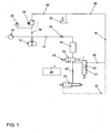
- a preferred embodiment of an injection system according to the invention for an internal combustion engine for example for a diesel engine, comprises a high-pressure pump 10 and a fuel distribution pipe or a rail 12 from which a line 14 with a throttle 16 branches off to an injector or engine cylinder.
- the injector essentially comprises an injector volume 18, a quantity valve 20 in the form of a 2/2-way valve which is driven, for example, by a piezo element or an electromagnet (not shown), a pressure adjusting valve 22 in the form of a 2/3-way valve and an injection nozzle 24, with nozzle needle spring (passive nozzle).
- the injection system includes a rail pressure sensor 26 connected to the fuel rail 12, a pressure regulating valve 28 regulating the pressure in the fuel rail 12, a fuel tank 30, and a drain line 28 connected to the pressure regulating valve 28, the fuel tank 30, the stem pressure adjusting valve 22, and the injector 24.
- Denoted at 34 is an electrical control for the flow control valve 20.
- a fuel line or return line 36 connects the fuel tank 30 to the pressure adjusting valve 22 and via the pressure control valve 28 to the Kraftstoffverteilrohr 12.
- For damping the pressure surges generated by the piston of the high-pressure pump 10 is located; between the rail 12 and the injector memory 18 at least one throttle 16.
- the throttle may be integrated into the injector or into the rail 12.
- the length of the line 14 between the rail 12 and the injector is the same for all cylinders.
- the injector memory 18 is formed generated by a hollow of the injector body.
- the injection quantity release takes place through the 2/2-way valve 20 (flow control valve).
- the 2/3-way valve 22 stabilizes the positive pressure between the injector 24 and the flow control valve 20.
- the leak oil flows, possibly through a radiator (not shown), via the leak oil line 32 and the fuel line 36 back to the fuel tank 30.
- the lines in the injector are as short as possible.
- a first line 40 connects the injector 24 to the flow control valve 20.
- a connection of the pressure adjusting valve 22 is connected to the first line 40.
- the quantity valve is acted upon by a spring 44 in the direction of the closed position with force.
- the 2/3-way valve 22 has three positions, which in addition Fig. 3 to 5 are illustrated.
- a first switching position according to Fig. 3 the 2/3-way valve 22 is closed.
- a second switching position according to Fig. 4 connects the 2/3-way valve 22, the first line 40 to the return line 36 via a formed in the 2/3-way valve 22 throttle 46.
- a third switching position according to Fig. 5 this connection between the first line 40 and the return line 36 is disconnected again.
- the 2/3-way valve 22 is designed such that a pressure applied via the first line 40 in the 2/3-way valve 22 switches between the aforementioned switching positions.
- Fig. 2 a second preferred embodiment of a fuel injection system according to the invention is shown, wherein like reference numerals have functionally identical parts as in Fig. 1 and 3 to 5 so that their explanation in the above description of the Fig. 1 and 3 to 5 is referenced.
- Fig. 1 includes the second embodiment according to Fig. 2 a counter-piston 38 at the injection nozzle 24.
- a space for the opposed piston 38 is connected via a second line 42 to the injector volume 18. This counter-piston 38 exerts an additional closing force on the injection nozzle 24.
- the actuator which actuates the quantity valve 20 is optionally activated in such a way that the quantity valve 20 executes only a partial stroke.
- the injection rate is represented by throttling via the flow control valve 20. Since it is a 2/2-way valve 20, this throttling does not lead to a reduction of the volumetric efficiency.
- a seat throttling in the injection nozzle as provided for example in conventional, known CR (common rail) systems, the mixture forming quality is improved.
- the seat throttling leads to cavitation before and in the nozzle holes and thus to an irregular or uneven distribution of the fuel to the individual injection holes.
- the second embodiment according to Fig. 2 acts a constantly biased by the pressure in the injector memory 18 piston 38 in addition to the back of the nozzle needle 24 a.
- the nozzle opening and closing pressure increases with the rail pressure. This allows an additional degree of freedom in the tuning of the injection system.
- the function corresponds to that of the first embodiment according to FIG Fig. 1 , Like previously described.
- the flow control valve 20 is 100% static pressure balanced to minimize the actuating forces.
- the effective cross section of the flow control valve 20 is, for example 4 times, preferably 4 1/2 times as large as that of the injection nozzle 24, so that no appreciable pressure loss via the flow control valve 20 occurs.
- the 2/3-way valve 22 is in the starting position ( Fig. 3 ) a seat valve.
- the 2nd switch position and the 3rd switch position are sealed via gaps (slide valve), as shown 4 and 5 seen.
- the seat seal in the starting position ( Fig. 3 ) allows a secure holding of the stand pressure, since no leakage occurs over the closed valve 22.
- the passing through the valve 22 amount can be in the embodiment according to Fig. 6 over the length of a plug 48, which releases a throttle cross-section (throttle edge) set. Alternatively, this can be done by adjusting the (transverse) bore diameter in the valve spool.
- FIG. 7 An enlargement of the pressure spread between the first switching positions ( Fig. 3 ) and the third switch position ( Fig. 5 ) can be achieved by placing the seat of the poppet valve on a larger diameter than the pusher diameter, as in Fig. 7 shown.
- the sealing diameter for the initial position (first switching position) is analog Fig. 3 designated.
- the sealing diameter for the third switching position is analog Fig. 5 designated.
- the pressures, and thus the required spring forces behave like the diameters associated surfaces on which is sealed.
- the line pressure acting on the upper face shifts the valve spool.
- the spring force and the spring stiffness, together with the valve travel determine the pressures for the two switching stages.
- the connection of the branch line to the 2/3-way valve 22 is located in the immediate vicinity of the flow control valve 20 to "level" or to absorb the returning pressure wave after closing the injector 24 there.
- the injection quantity is metered directly via the quantity valve 20. This eliminates the errors from the timing chain of a conventional injector.
- a pilot valve is moved via an electromagnet or a piezo actuator. This in turn relieves the back of the injection needle. This lifts off the needle seat and the injection begins.
- the pilot valve is closed, which leads to a pressure build-up on the back of the injection needle and the initiation of the closing movement.
- the pressure wave is effectively calmed, which minimizes the quantity effect on the individual injections.
- the injection quantity corresponds to the amount taken from the reservoir, taking into account the small amount that escapes during pressure build-up and pressure reduction by the 2/3-way valve 22.
- This Abgresmenge is independent of the injection quantity, it is easily influenced by the accumulator pressure.
- the Abberichtmenge is small ( ⁇ 2mm 3 ).
- the operational safety is increased by the 2/3-way valve 22, since small leaks (leaking flow control valve) by shifting the 2/3-way valve 22 in the second switching position ( Fig. 4 ) are intercepted without it comes to a permanent injection.
- the injector memory 18 is dimensioned large and oriented in the direction of the injector needle axis.
- the actuator is roughly oriented in the direction of the injector needle axis (on nozzle).
- the injector memory 18 and the high-pressure port are arranged laterally.
- the present invention can also be used as injector control for the CRID. In this case, the injector memory 18 is replaced by the pressure booster of the CRID.
Landscapes
- Engineering & Computer Science (AREA)
- Chemical & Material Sciences (AREA)
- Combustion & Propulsion (AREA)
- Mechanical Engineering (AREA)
- General Engineering & Computer Science (AREA)
- Fuel-Injection Apparatus (AREA)
Applications Claiming Priority (1)
| Application Number | Priority Date | Filing Date | Title |
|---|---|---|---|
| DE200810015857 DE102008015857A1 (de) | 2008-03-27 | 2008-03-27 | Kraftstoffeinspritzsystem für eine Brennkraftmaschine |
Publications (3)
| Publication Number | Publication Date |
|---|---|
| EP2105604A2 true EP2105604A2 (fr) | 2009-09-30 |
| EP2105604A3 EP2105604A3 (fr) | 2010-11-17 |
| EP2105604B1 EP2105604B1 (fr) | 2013-04-10 |
Family
ID=40810086
Family Applications (1)
| Application Number | Title | Priority Date | Filing Date |
|---|---|---|---|
| EP09001412.7A Not-in-force EP2105604B1 (fr) | 2008-03-27 | 2009-02-02 | Système d'injection de carburant pour un moteur à combustion interne |
Country Status (2)
| Country | Link |
|---|---|
| EP (1) | EP2105604B1 (fr) |
| DE (1) | DE102008015857A1 (fr) |
Families Citing this family (1)
| Publication number | Priority date | Publication date | Assignee | Title |
|---|---|---|---|---|
| DE102014210779A1 (de) | 2014-06-05 | 2015-12-17 | Volkswagen Aktiengesellschaft | Kraftstoffeinspritzvorrichtung |
Family Cites Families (6)
| Publication number | Priority date | Publication date | Assignee | Title |
|---|---|---|---|---|
| DE3009750C2 (de) * | 1980-03-14 | 1987-01-02 | M.A.N.- B & W Diesel GmbH, 8900 Augsburg | Brennstoffeinspritzvorrichtung für Brennkraftmaschinen |
| AT2961U3 (de) * | 1998-07-02 | 1999-11-25 | Avl List Gmbh | Speichereinspritzeinrichtung |
| GB9822653D0 (en) * | 1998-10-17 | 1998-12-09 | Lucas Ind Plc | Fuel system |
| DE10033428C2 (de) * | 2000-07-10 | 2002-07-11 | Bosch Gmbh Robert | Druckgesteuerter Injektor zum Einspritzen von Kraftstoff |
| DE10046662B4 (de) * | 2000-09-20 | 2004-09-30 | Robert Bosch Gmbh | Kraftstoffeinspritzventil mit einem Druckhalteventil |
| DE10330132A1 (de) * | 2003-07-04 | 2005-01-20 | Robert Bosch Gmbh | Druckhalteventil, Werkzeug, Set und Kraftstoffeinspritzsystem |
-
2008
- 2008-03-27 DE DE200810015857 patent/DE102008015857A1/de not_active Withdrawn
-
2009
- 2009-02-02 EP EP09001412.7A patent/EP2105604B1/fr not_active Not-in-force
Non-Patent Citations (1)
| Title |
|---|
| None |
Also Published As
| Publication number | Publication date |
|---|---|
| EP2105604B1 (fr) | 2013-04-10 |
| EP2105604A3 (fr) | 2010-11-17 |
| DE102008015857A1 (de) | 2009-10-01 |
Similar Documents
| Publication | Publication Date | Title |
|---|---|---|
| EP1654456B1 (fr) | Dispositif d'injection de carburant pour moteur a combustion interne | |
| EP1125046B1 (fr) | System d'injection de carburant pour un moteur à combustion interne avec un multiplicateur de pression | |
| DE10024268B4 (de) | Vorrichtung zur Benzindirekteinspritzung in einer Kolbenbrennkraftmaschine | |
| EP1392966A1 (fr) | Systeme d'injection de carburant pourvu d'un dispositif multiplicateur de pression et dispositif multiplicateur de pression | |
| WO2001088365A1 (fr) | Systeme d'injection pour systeme accumulateur-injecteur de carburant de moteur a combustion interne | |
| DE102004053421A1 (de) | Kraftstoffeinspritzvorrichtung | |
| WO2004003376A1 (fr) | Injecteur de carburant a multiplicateur de pression a reduction de pression rapide lors de l'injection | |
| EP1925812B1 (fr) | Soupape d'injection de carburant pour moteurs à combustion interne | |
| EP1187984B1 (fr) | Valve de commande et soupape d'injection de carburant dotee de cette valve de commande | |
| EP2835526B1 (fr) | Agencement de vannes pour une installation d'alimentation en carburant et installation d'alimentation en carburant | |
| EP2156050B1 (fr) | Système d'amplification de pression pour au moins un injecteur de carburant | |
| DE19640085C1 (de) | Sperrventil zur Durchflußmengenbegrenzung | |
| EP2105604B1 (fr) | Système d'injection de carburant pour un moteur à combustion interne | |
| DE102018200565A1 (de) | Injektor zur Dosierung von gasförmigem Kraftstoff, Gaseinblassystem mit einem solchen Injektor und Verfahren zum Betreiben dieses Injektors | |
| DE19945785A1 (de) | Kraftstoffeinspritzsystem für Brennkraftmaschinen und Verfahren zum Einspritzen von Kraftstoff in den Brennraum einer Brennkraftmaschine | |
| DE102015226070A1 (de) | Kraftstoffinjektor | |
| DE102007005382A1 (de) | Leckagefreier Injektor | |
| DE10132248C2 (de) | Kraftstoffinjektor mit 2-Wege-Ventilsteuerung | |
| DE10357873A1 (de) | Einspritzventil | |
| EP1920156B1 (fr) | Systeme d'injection de carburant pour un moteur a combustion interne | |
| DE102006026877A1 (de) | Kraftstoff-Einspritzvorrichtung für eine Brennkraftmaschine | |
| EP1313945B1 (fr) | Soupape d'injection pour l'injection de carburant dans un moteur a combustion interne et procede pour commander l'ouverture et la fermeture d'une aiguille d'une soupape d'injection | |
| DE102007001365A1 (de) | Injektor mit Steuer- und Schaltkammer | |
| DE10300385B3 (de) | Kraftstoffeinspritzvorrichtung mit schnell schließendem 3/3-Wege-Steuerventil | |
| DE102004028886A1 (de) | Kraftstoffeinspritzeinrichtung |
Legal Events
| Date | Code | Title | Description |
|---|---|---|---|
| PUAI | Public reference made under article 153(3) epc to a published international application that has entered the european phase |
Free format text: ORIGINAL CODE: 0009012 |
|
| AK | Designated contracting states |
Kind code of ref document: A2 Designated state(s): AT BE BG CH CY CZ DE DK EE ES FI FR GB GR HR HU IE IS IT LI LT LU LV MC MK MT NL NO PL PT RO SE SI SK TR |
|
| AX | Request for extension of the european patent |
Extension state: AL BA RS |
|
| PUAL | Search report despatched |
Free format text: ORIGINAL CODE: 0009013 |
|
| AK | Designated contracting states |
Kind code of ref document: A3 Designated state(s): AT BE BG CH CY CZ DE DK EE ES FI FR GB GR HR HU IE IS IT LI LT LU LV MC MK MT NL NO PL PT RO SE SI SK TR |
|
| AX | Request for extension of the european patent |
Extension state: AL BA RS |
|
| RIC1 | Information provided on ipc code assigned before grant |
Ipc: F02M 63/00 20060101AFI20101012BHEP Ipc: F02M 61/20 20060101ALI20101012BHEP Ipc: F02M 63/02 20060101ALI20101012BHEP |
|
| 17P | Request for examination filed |
Effective date: 20110517 |
|
| AKX | Designation fees paid |
Designated state(s): AT BE BG CH CY CZ DE DK EE ES FI FR GB GR HR HU IE IS IT LI LT LU LV MC MK MT NL NO PL PT RO SE SI SK TR |
|
| RIC1 | Information provided on ipc code assigned before grant |
Ipc: F02M 63/02 20060101ALI20120126BHEP Ipc: F02M 63/00 20060101AFI20120126BHEP Ipc: F02M 61/20 20060101ALI20120126BHEP Ipc: F02M 37/00 20060101ALI20120126BHEP |
|
| 17Q | First examination report despatched |
Effective date: 20120427 |
|
| RAP1 | Party data changed (applicant data changed or rights of an application transferred) |
Owner name: VOLKSWAGEN AKTIENGESELLSCHAFT |
|
| GRAP | Despatch of communication of intention to grant a patent |
Free format text: ORIGINAL CODE: EPIDOSNIGR1 |
|
| GRAS | Grant fee paid |
Free format text: ORIGINAL CODE: EPIDOSNIGR3 |
|
| GRAA | (expected) grant |
Free format text: ORIGINAL CODE: 0009210 |
|
| AK | Designated contracting states |
Kind code of ref document: B1 Designated state(s): AT BE BG CH CY CZ DE DK EE ES FI FR GB GR HR HU IE IS IT LI LT LU LV MC MK MT NL NO PL PT RO SE SI SK TR |
|
| REG | Reference to a national code |
Ref country code: GB Ref legal event code: FG4D Free format text: NOT ENGLISH |
|
| REG | Reference to a national code |
Ref country code: AT Ref legal event code: REF Ref document number: 606156 Country of ref document: AT Kind code of ref document: T Effective date: 20130415 Ref country code: CH Ref legal event code: EP |
|
| REG | Reference to a national code |
Ref country code: IE Ref legal event code: FG4D Free format text: LANGUAGE OF EP DOCUMENT: GERMAN |
|
| REG | Reference to a national code |
Ref country code: DE Ref legal event code: R096 Ref document number: 502009006761 Country of ref document: DE Effective date: 20130606 |
|
| PG25 | Lapsed in a contracting state [announced via postgrant information from national office to epo] |
Ref country code: SI Free format text: LAPSE BECAUSE OF FAILURE TO SUBMIT A TRANSLATION OF THE DESCRIPTION OR TO PAY THE FEE WITHIN THE PRESCRIBED TIME-LIMIT Effective date: 20130410 |
|
| REG | Reference to a national code |
Ref country code: LT Ref legal event code: MG4D Ref country code: NL Ref legal event code: VDEP Effective date: 20130410 |
|
| PG25 | Lapsed in a contracting state [announced via postgrant information from national office to epo] |
Ref country code: ES Free format text: LAPSE BECAUSE OF FAILURE TO SUBMIT A TRANSLATION OF THE DESCRIPTION OR TO PAY THE FEE WITHIN THE PRESCRIBED TIME-LIMIT Effective date: 20130721 Ref country code: PT Free format text: LAPSE BECAUSE OF FAILURE TO SUBMIT A TRANSLATION OF THE DESCRIPTION OR TO PAY THE FEE WITHIN THE PRESCRIBED TIME-LIMIT Effective date: 20130812 Ref country code: LT Free format text: LAPSE BECAUSE OF FAILURE TO SUBMIT A TRANSLATION OF THE DESCRIPTION OR TO PAY THE FEE WITHIN THE PRESCRIBED TIME-LIMIT Effective date: 20130410 Ref country code: NL Free format text: LAPSE BECAUSE OF FAILURE TO SUBMIT A TRANSLATION OF THE DESCRIPTION OR TO PAY THE FEE WITHIN THE PRESCRIBED TIME-LIMIT Effective date: 20130410 Ref country code: FI Free format text: LAPSE BECAUSE OF FAILURE TO SUBMIT A TRANSLATION OF THE DESCRIPTION OR TO PAY THE FEE WITHIN THE PRESCRIBED TIME-LIMIT Effective date: 20130410 Ref country code: NO Free format text: LAPSE BECAUSE OF FAILURE TO SUBMIT A TRANSLATION OF THE DESCRIPTION OR TO PAY THE FEE WITHIN THE PRESCRIBED TIME-LIMIT Effective date: 20130710 Ref country code: GR Free format text: LAPSE BECAUSE OF FAILURE TO SUBMIT A TRANSLATION OF THE DESCRIPTION OR TO PAY THE FEE WITHIN THE PRESCRIBED TIME-LIMIT Effective date: 20130711 Ref country code: IS Free format text: LAPSE BECAUSE OF FAILURE TO SUBMIT A TRANSLATION OF THE DESCRIPTION OR TO PAY THE FEE WITHIN THE PRESCRIBED TIME-LIMIT Effective date: 20130810 Ref country code: SE Free format text: LAPSE BECAUSE OF FAILURE TO SUBMIT A TRANSLATION OF THE DESCRIPTION OR TO PAY THE FEE WITHIN THE PRESCRIBED TIME-LIMIT Effective date: 20130410 |
|
| PG25 | Lapsed in a contracting state [announced via postgrant information from national office to epo] |
Ref country code: LV Free format text: LAPSE BECAUSE OF FAILURE TO SUBMIT A TRANSLATION OF THE DESCRIPTION OR TO PAY THE FEE WITHIN THE PRESCRIBED TIME-LIMIT Effective date: 20130410 Ref country code: PL Free format text: LAPSE BECAUSE OF FAILURE TO SUBMIT A TRANSLATION OF THE DESCRIPTION OR TO PAY THE FEE WITHIN THE PRESCRIBED TIME-LIMIT Effective date: 20130410 Ref country code: BG Free format text: LAPSE BECAUSE OF FAILURE TO SUBMIT A TRANSLATION OF THE DESCRIPTION OR TO PAY THE FEE WITHIN THE PRESCRIBED TIME-LIMIT Effective date: 20130710 Ref country code: HR Free format text: LAPSE BECAUSE OF FAILURE TO SUBMIT A TRANSLATION OF THE DESCRIPTION OR TO PAY THE FEE WITHIN THE PRESCRIBED TIME-LIMIT Effective date: 20130410 Ref country code: CY Free format text: LAPSE BECAUSE OF FAILURE TO SUBMIT A TRANSLATION OF THE DESCRIPTION OR TO PAY THE FEE WITHIN THE PRESCRIBED TIME-LIMIT Effective date: 20130410 |
|
| PG25 | Lapsed in a contracting state [announced via postgrant information from national office to epo] |
Ref country code: EE Free format text: LAPSE BECAUSE OF FAILURE TO SUBMIT A TRANSLATION OF THE DESCRIPTION OR TO PAY THE FEE WITHIN THE PRESCRIBED TIME-LIMIT Effective date: 20130410 Ref country code: CZ Free format text: LAPSE BECAUSE OF FAILURE TO SUBMIT A TRANSLATION OF THE DESCRIPTION OR TO PAY THE FEE WITHIN THE PRESCRIBED TIME-LIMIT Effective date: 20130410 Ref country code: SK Free format text: LAPSE BECAUSE OF FAILURE TO SUBMIT A TRANSLATION OF THE DESCRIPTION OR TO PAY THE FEE WITHIN THE PRESCRIBED TIME-LIMIT Effective date: 20130410 Ref country code: DK Free format text: LAPSE BECAUSE OF FAILURE TO SUBMIT A TRANSLATION OF THE DESCRIPTION OR TO PAY THE FEE WITHIN THE PRESCRIBED TIME-LIMIT Effective date: 20130410 |
|
| PLBE | No opposition filed within time limit |
Free format text: ORIGINAL CODE: 0009261 |
|
| STAA | Information on the status of an ep patent application or granted ep patent |
Free format text: STATUS: NO OPPOSITION FILED WITHIN TIME LIMIT |
|
| PG25 | Lapsed in a contracting state [announced via postgrant information from national office to epo] |
Ref country code: RO Free format text: LAPSE BECAUSE OF FAILURE TO SUBMIT A TRANSLATION OF THE DESCRIPTION OR TO PAY THE FEE WITHIN THE PRESCRIBED TIME-LIMIT Effective date: 20130410 Ref country code: IT Free format text: LAPSE BECAUSE OF FAILURE TO SUBMIT A TRANSLATION OF THE DESCRIPTION OR TO PAY THE FEE WITHIN THE PRESCRIBED TIME-LIMIT Effective date: 20130410 |
|
| 26N | No opposition filed |
Effective date: 20140113 |
|
| REG | Reference to a national code |
Ref country code: DE Ref legal event code: R097 Ref document number: 502009006761 Country of ref document: DE Effective date: 20140113 |
|
| BERE | Be: lapsed |
Owner name: VOLKSWAGEN A.G. Effective date: 20140228 |
|
| PG25 | Lapsed in a contracting state [announced via postgrant information from national office to epo] |
Ref country code: LU Free format text: LAPSE BECAUSE OF FAILURE TO SUBMIT A TRANSLATION OF THE DESCRIPTION OR TO PAY THE FEE WITHIN THE PRESCRIBED TIME-LIMIT Effective date: 20140202 Ref country code: MC Free format text: LAPSE BECAUSE OF FAILURE TO SUBMIT A TRANSLATION OF THE DESCRIPTION OR TO PAY THE FEE WITHIN THE PRESCRIBED TIME-LIMIT Effective date: 20130410 |
|
| REG | Reference to a national code |
Ref country code: CH Ref legal event code: PL |
|
| PG25 | Lapsed in a contracting state [announced via postgrant information from national office to epo] |
Ref country code: LI Free format text: LAPSE BECAUSE OF NON-PAYMENT OF DUE FEES Effective date: 20140228 Ref country code: CH Free format text: LAPSE BECAUSE OF NON-PAYMENT OF DUE FEES Effective date: 20140228 |
|
| REG | Reference to a national code |
Ref country code: IE Ref legal event code: MM4A |
|
| PG25 | Lapsed in a contracting state [announced via postgrant information from national office to epo] |
Ref country code: BE Free format text: LAPSE BECAUSE OF NON-PAYMENT OF DUE FEES Effective date: 20140228 Ref country code: IE Free format text: LAPSE BECAUSE OF NON-PAYMENT OF DUE FEES Effective date: 20140202 |
|
| REG | Reference to a national code |
Ref country code: FR Ref legal event code: PLFP Year of fee payment: 7 |
|
| REG | Reference to a national code |
Ref country code: AT Ref legal event code: MM01 Ref document number: 606156 Country of ref document: AT Kind code of ref document: T Effective date: 20140202 |
|
| PGFP | Annual fee paid to national office [announced via postgrant information from national office to epo] |
Ref country code: DE Payment date: 20150228 Year of fee payment: 7 |
|
| PG25 | Lapsed in a contracting state [announced via postgrant information from national office to epo] |
Ref country code: AT Free format text: LAPSE BECAUSE OF NON-PAYMENT OF DUE FEES Effective date: 20140202 |
|
| PGFP | Annual fee paid to national office [announced via postgrant information from national office to epo] |
Ref country code: GB Payment date: 20150227 Year of fee payment: 7 Ref country code: FR Payment date: 20150227 Year of fee payment: 7 |
|
| PG25 | Lapsed in a contracting state [announced via postgrant information from national office to epo] |
Ref country code: MT Free format text: LAPSE BECAUSE OF FAILURE TO SUBMIT A TRANSLATION OF THE DESCRIPTION OR TO PAY THE FEE WITHIN THE PRESCRIBED TIME-LIMIT Effective date: 20130410 |
|
| PG25 | Lapsed in a contracting state [announced via postgrant information from national office to epo] |
Ref country code: TR Free format text: LAPSE BECAUSE OF FAILURE TO SUBMIT A TRANSLATION OF THE DESCRIPTION OR TO PAY THE FEE WITHIN THE PRESCRIBED TIME-LIMIT Effective date: 20130410 Ref country code: HU Free format text: LAPSE BECAUSE OF FAILURE TO SUBMIT A TRANSLATION OF THE DESCRIPTION OR TO PAY THE FEE WITHIN THE PRESCRIBED TIME-LIMIT; INVALID AB INITIO Effective date: 20090202 |
|
| REG | Reference to a national code |
Ref country code: DE Ref legal event code: R119 Ref document number: 502009006761 Country of ref document: DE |
|
| GBPC | Gb: european patent ceased through non-payment of renewal fee |
Effective date: 20160202 |
|
| REG | Reference to a national code |
Ref country code: FR Ref legal event code: ST Effective date: 20161028 |
|
| PG25 | Lapsed in a contracting state [announced via postgrant information from national office to epo] |
Ref country code: DE Free format text: LAPSE BECAUSE OF NON-PAYMENT OF DUE FEES Effective date: 20160901 Ref country code: FR Free format text: LAPSE BECAUSE OF NON-PAYMENT OF DUE FEES Effective date: 20160229 Ref country code: GB Free format text: LAPSE BECAUSE OF NON-PAYMENT OF DUE FEES Effective date: 20160202 |
|
| PG25 | Lapsed in a contracting state [announced via postgrant information from national office to epo] |
Ref country code: MK Free format text: LAPSE BECAUSE OF FAILURE TO SUBMIT A TRANSLATION OF THE DESCRIPTION OR TO PAY THE FEE WITHIN THE PRESCRIBED TIME-LIMIT Effective date: 20130410 |