EP2105663A1 - Dispositif d'exécution de processus thermiques, dans lesquels une flamme est utilisée comme source d'énergie thermique - Google Patents
Dispositif d'exécution de processus thermiques, dans lesquels une flamme est utilisée comme source d'énergie thermique Download PDFInfo
- Publication number
- EP2105663A1 EP2105663A1 EP08006149A EP08006149A EP2105663A1 EP 2105663 A1 EP2105663 A1 EP 2105663A1 EP 08006149 A EP08006149 A EP 08006149A EP 08006149 A EP08006149 A EP 08006149A EP 2105663 A1 EP2105663 A1 EP 2105663A1
- Authority
- EP
- European Patent Office
- Prior art keywords
- combustion chamber
- flue gases
- flame
- ceramic
- chamber
- Prior art date
- Legal status (The legal status is an assumption and is not a legal conclusion. Google has not performed a legal analysis and makes no representation as to the accuracy of the status listed.)
- Granted
Links
Images


Classifications
-
- F—MECHANICAL ENGINEERING; LIGHTING; HEATING; WEAPONS; BLASTING
- F23—COMBUSTION APPARATUS; COMBUSTION PROCESSES
- F23G—CREMATION FURNACES; CONSUMING WASTE PRODUCTS BY COMBUSTION
- F23G7/00—Incinerators or other apparatus for consuming industrial waste, e.g. chemicals
- F23G7/06—Incinerators or other apparatus for consuming industrial waste, e.g. chemicals of waste gases or noxious gases, e.g. exhaust gases
- F23G7/061—Incinerators or other apparatus for consuming industrial waste, e.g. chemicals of waste gases or noxious gases, e.g. exhaust gases with supplementary heating
- F23G7/065—Incinerators or other apparatus for consuming industrial waste, e.g. chemicals of waste gases or noxious gases, e.g. exhaust gases with supplementary heating using gaseous or liquid fuel
- F23G7/066—Incinerators or other apparatus for consuming industrial waste, e.g. chemicals of waste gases or noxious gases, e.g. exhaust gases with supplementary heating using gaseous or liquid fuel preheating the waste gas by the heat of the combustion, e.g. recuperation type incinerator
- F23G7/068—Incinerators or other apparatus for consuming industrial waste, e.g. chemicals of waste gases or noxious gases, e.g. exhaust gases with supplementary heating using gaseous or liquid fuel preheating the waste gas by the heat of the combustion, e.g. recuperation type incinerator using regenerative heat recovery means
-
- F—MECHANICAL ENGINEERING; LIGHTING; HEATING; WEAPONS; BLASTING
- F23—COMBUSTION APPARATUS; COMBUSTION PROCESSES
- F23G—CREMATION FURNACES; CONSUMING WASTE PRODUCTS BY COMBUSTION
- F23G5/00—Incineration of waste; Incinerator constructions; Details, accessories or control therefor
- F23G5/24—Incineration of waste; Incinerator constructions; Details, accessories or control therefor having a vertical, substantially cylindrical, combustion chamber
Definitions
- the invention relates to a device for carrying out thermal processes in which a flame is used as the thermal energy source, according to the preamble of claim 1.
- the thermal processes of this type may be, for example, drying and preheating of pans, containers or melting furnace in steel plants or manufacturing processes in ferrous and non-ferrous metal metallurgy.
- the thermal processes carried out in a combustion chamber are accompanied by a combustion process which takes place with the supply of combustion air and in which not only the fuel supplied to generate the flame from a main burner is burned, but also the vapors and gases produced during the thermal treatment, the of the treated material, eg from molten metal.
- Combustion processes are known to be associated with pollutant emissions, the pollutants and other emissions (noise, odor, etc.) may not be released freely to the environment for environmental protection reasons.
- a particular problem is the formation of nitrogen oxides (NO x ), which can lead to respiratory disease and multiple damage to sensitive ecosystems, and a precursor substance for the formation of acid precipitation, secondary aerosols and - together with the volatile organic compounds - of Photooxidants (ozone / summer smog) represent.
- NO x nitrogen oxides
- the combustion chamber must be followed by a post-combustion chamber with another burner and gas cleaning systems, whereby certain temperatures are necessary for the purification of the flue gases.
- the gas purification takes place in several stages, whereby the nitrogen oxides are reduced by the addition of ammonia to nitrogen. All these additional systems - not least also monitoring of noise caused by flame generation, as well as a system of exhaust hoods and filters - are associated with an increased consumption of electricity and fuel.
- the present invention has for its object to provide a device of the type mentioned, with the thermal processes or the processes accompanying these processes can be carried out environmentally friendly and yet with significantly reduced costs.
- the combustion chamber communicates with at least three regeneration chambers which can be connected to the supply line for the combustion air or to the exhaust line for the flue gases and which are each provided with a heatable ceramic bed.
- the combustion air is alternately fed into the combustion chamber via one of the regeneration chambers and thereby heated and the flue gases are removed via another regeneration chamber and thereby cooled, with the sequence of connection of the individual Regenerlerhuntn to the supply or to the suction line (or to none of both) is changed periodically.
- auxiliary burners are preferably arranged in the regeneration chambers.
- the low nitrogen emission in the combustion carried out in the inventive device which is at a controlled temperature.
- Any unburned gases and / or volatile organic substances are thermally destroyed in the ceramic beds maintained at 750 ° C or in the overlying zones with the auxiliary burner flames, and the gases in the ceramic beds are cooled to a temperature below 300 ° C.
- the pollutants are already eliminated within the inventive device and the flue gases cleaned, and more, platz contactsspruchende Nachverbrennungs- and Nach lenderssvorraumen unnecessary, which in turn brings a huge cost savings (in investment, maintenance, fuel and electricity consumption, etc.) with it.
- the ceramic beds also contribute to the acoustic absorption, so that the noise generated during flame generation is also reduced.
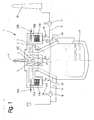
- Fig.1 shows an apparatus 1 for performing a thermal process, such as a melting furnace.
- the device 1 has a refractory housing 2, which encloses a combustion chamber 3.
- a combustion chamber 3 Into the housing 2 projects from above a main burner 4 as a central lance, which serves to generate a flame 5 as a thermal energy source for performing the thermal process (eg, melting).
- a combustion process takes place above the melt 6, in which not only the fuel is burned to produce the flame, but also the resulting during the thermal treatment vapors and gases coming from the treating material, such as the molten metal 6.
- the combustion chamber 3 communicates with three regeneration chambers 10A, 10B, 10C accommodated in the upper region of the housing 2, of which FIG Fig. 1 for simplicity, two are shown in the same plane of the drawing. How, however, out Fig. 2a to 2m
- the three regeneration chambers 10A, 10B, 10C are uniformly distributed around the circumference of the combustion chamber 3.
- Each regeneration chamber 10A, 10B, 10C contains a per se known ceramic bed 11A, 11B, 11C and is connected via a respective valve VA, VF to a supply line 14 for the combustion air (oxygen-containing gases) on the one hand and to an exhaust duct 15 for the flue gases on the other hand.
- the supplied by means of a blower 16 combustion air is introduced at the open valve VA, for example, to the regeneration chamber 10A and the ceramic bed 11A in the combustion chamber 3 and the flue gases through a ceramic bed another Regenerierhunt, eg the Regenerierhunt 10B, the valve VF is open by means of a Suction blower 17 withdrawn and passed into a chimney 18.
- an auxiliary burner 20A, 20B, 20C is disposed above the ceramic bed 11A, 11B, 11C, respectively, facing the main burner 4 and its flame 5 (ie, three auxiliary burners 20A, 20B, 20C preferably arranged perpendicular to the central axis a of the device 1, which enclose an angle of 120 ° with each other).
- auxiliary burners 20A, 20B, 20C placed between the combustion chamber 3 and the respective ceramic bed 11A, 11B, 11C ensure that in these zones and in the upper third of each ceramic bed 11A, 11B, 11C a temperature of at least 750 ° C is reached and maintained ,
- the entering into the combustion chamber 3 combustion air is heated in the corresponding ceramic bed and the overlying zone and the exiting flue gases cooled in the corresponding other ceramic bed to a temperature between 230 ° C and 260 ° C, with any unburned gases and / or volatile organic substances in the overheated part of the other ceramic bed (or already in the overlying zone) are thermally destroyed.
- the ceramic beds alternately absorb the heat from the exiting flue gases and deliver it to the incoming combustion air, whereby an enormous energy saving is achieved.
- the temperature in the upper third of the ceramic beds is measured continuously and secured by regulating the amount of fuel in the auxiliary burners 20A, 20B, 20C.
- the ceramic beds 11A, 11B, 11C are brought to the working temperature with a reduced air flow rate by means of the auxiliary burners 20A, 20B, 20C. Thereafter, the actual process begins, in which the main burner 4 is used.
- the main burner 4 As the main burner 4, a so-called LNI (Low Nox Iniection) burner is used.
- LNI Low Nox Iniection
- the ignition phase the amount of fuel added via the main burner 4 is minimal and the flame 5 is quiet, mixing with the warm combustion air. Thereafter, the capacity and the amount of combustion air are automatically increased.
- the work cycle is as follows:
- Fig. 2a the combustion air is introduced into the first regeneration chamber 10A (arrow A) and heated there, and the flue gases are withdrawn through the second regeneration chamber 10B (arrow F).
- the third regeneration chamber 10C is shaded (standby mode in which also the corresponding auxiliary burner 20C is out of operation).
- the amount of fuel introduced via the main burner is regulated together with the amount of combustion air, in accordance with the process parameters and the temperature in the second regeneration chamber 10B.
- the flue gases release their heat to the second ceramic bed 11B. This first phase continues until an inversion temperature is reached in the second regeneration chamber 10B and the flue gases have cooled to about 260.degree.
- the third regeneration chamber 10C is connected to the exhaust pipe 15 and the flue gases are discharged through both Regenerierhuntn 10B and 10C ( Fig. 2b ) before the exit from the second regeneration chamber 10B is closed via the corresponding valve VF ( Fig. 2c ). Now, the third ceramic bed 11C is heated by the flue gases.
- the second regeneration chamber 10B is connected to the supply line 14 via the corresponding valve VA and the combustion air is introduced into the combustion chamber 3 via both the first and second regeneration chambers 10A, 10B.
- the flue gases escape via the third regeneration chamber 10C (FIG. Fig. 2d ).
- the first regeneration chamber 10A is connected to the exhaust duct 15, the combustion air is still supplied via the second regeneration chamber 10B and the flue gases are discharged via the regeneration chambers 10C, 10A ( Fig. 2f ) until the exit from the third regeneration chamber 10C is closed ( Fig. 2g ).
- the second regeneration chamber 10B is opened for flue gases ( Fig. 2j ) and these escape via the first and the second regeneration chamber 10A, 10B before the first regeneration chamber 10A is closed for them ( Fig. 2k ).
- the flue gases release their heat to the second ceramic bed 11B.
- the first regeneration chamber 10A for the combustion air is opened ( Fig. 2l ), then the air supply via the third ceramic bed 11C interrupted ( Fig. 2m ) and thus the the Fig. 2a corresponding output circuit is reached again.
- any unburned gases and / or volatile organic substances are thermally destroyed in the ceramic beds maintained at 750 ° C or in the overlying zones with the auxiliary burner flames, and the gases in the ceramic beds are cooled to a temperature below 300 ° C.
- the pollutants are already eliminated within the inventive device and the flue gases cleaned, and further, space-consuming Nachverbrennungs- and Nachtherapiesvorraumen unnecessary, which in turn brings a huge cost savings (in investment, maintenance, fuel and electricity consumption, etc.).
- the ceramic beds also contribute to the acoustic absorption, so that the noise generated during flame generation is reduced.
- the inversion of the flow can continuously follow combustion air / flue gases, without negative influence on the flame, which would be unavoidable in only two regeneration chambers.
Landscapes
- Engineering & Computer Science (AREA)
- Environmental & Geological Engineering (AREA)
- Mechanical Engineering (AREA)
- General Engineering & Computer Science (AREA)
- Air Supply (AREA)
- Waste-Gas Treatment And Other Accessory Devices For Furnaces (AREA)
Priority Applications (1)
| Application Number | Priority Date | Filing Date | Title |
|---|---|---|---|
| EP08006149.2A EP2105663B1 (fr) | 2008-03-28 | 2008-03-28 | Dispositif d'exécution de processus thermiques, dans lesquels une flamme est utilisée comme source d'énergie thermique |
Applications Claiming Priority (1)
| Application Number | Priority Date | Filing Date | Title |
|---|---|---|---|
| EP08006149.2A EP2105663B1 (fr) | 2008-03-28 | 2008-03-28 | Dispositif d'exécution de processus thermiques, dans lesquels une flamme est utilisée comme source d'énergie thermique |
Publications (2)
| Publication Number | Publication Date |
|---|---|
| EP2105663A1 true EP2105663A1 (fr) | 2009-09-30 |
| EP2105663B1 EP2105663B1 (fr) | 2016-01-06 |
Family
ID=39796826
Family Applications (1)
| Application Number | Title | Priority Date | Filing Date |
|---|---|---|---|
| EP08006149.2A Active EP2105663B1 (fr) | 2008-03-28 | 2008-03-28 | Dispositif d'exécution de processus thermiques, dans lesquels une flamme est utilisée comme source d'énergie thermique |
Country Status (1)
| Country | Link |
|---|---|
| EP (1) | EP2105663B1 (fr) |
Citations (6)
| Publication number | Priority date | Publication date | Assignee | Title |
|---|---|---|---|---|
| WO1990014560A1 (fr) | 1989-05-17 | 1990-11-29 | Walter Kanzler | Installation et procede pour traitement thermique d'effluents gazeux |
| US5707229A (en) * | 1993-07-12 | 1998-01-13 | Durr Industries, Inc. | Regenerative thermal oxidizer with heat exchanger columns |
| US6203316B1 (en) * | 1999-11-12 | 2001-03-20 | Regenerative Environmental Equipment Co., Inc. (Reeco, Inc.) | Continuous on-line smokeless bake-out process for a rotary oxidizer |
| EP1304526A2 (fr) * | 2001-10-09 | 2003-04-23 | Herhof Umwelttechnik Gmbh | Méthode et appareillage pour la purification des gaz de combustion |
| US20060121403A1 (en) | 2004-12-03 | 2006-06-08 | Thornton Lyman L | Regenerative thermal oxidizer |
| DE102007032952A1 (de) | 2006-09-12 | 2008-03-27 | Kba-Metalprint Gmbh | Verfahren zum Betreiben einer thermisch-regenerativen Abluftreinigungsanlage |
Family Cites Families (1)
| Publication number | Priority date | Publication date | Assignee | Title |
|---|---|---|---|---|
| DE1006107B (de) * | 1953-10-29 | 1957-04-11 | Eitel Hans Joachim | Herdofen, insbesondere Siemens-Martin-Ofen |
-
2008
- 2008-03-28 EP EP08006149.2A patent/EP2105663B1/fr active Active
Patent Citations (6)
| Publication number | Priority date | Publication date | Assignee | Title |
|---|---|---|---|---|
| WO1990014560A1 (fr) | 1989-05-17 | 1990-11-29 | Walter Kanzler | Installation et procede pour traitement thermique d'effluents gazeux |
| US5707229A (en) * | 1993-07-12 | 1998-01-13 | Durr Industries, Inc. | Regenerative thermal oxidizer with heat exchanger columns |
| US6203316B1 (en) * | 1999-11-12 | 2001-03-20 | Regenerative Environmental Equipment Co., Inc. (Reeco, Inc.) | Continuous on-line smokeless bake-out process for a rotary oxidizer |
| EP1304526A2 (fr) * | 2001-10-09 | 2003-04-23 | Herhof Umwelttechnik Gmbh | Méthode et appareillage pour la purification des gaz de combustion |
| US20060121403A1 (en) | 2004-12-03 | 2006-06-08 | Thornton Lyman L | Regenerative thermal oxidizer |
| DE102007032952A1 (de) | 2006-09-12 | 2008-03-27 | Kba-Metalprint Gmbh | Verfahren zum Betreiben einer thermisch-regenerativen Abluftreinigungsanlage |
Also Published As
| Publication number | Publication date |
|---|---|
| EP2105663B1 (fr) | 2016-01-06 |
Similar Documents
| Publication | Publication Date | Title |
|---|---|---|
| DE3729971C2 (fr) | ||
| DE3033641C2 (de) | System zur thermischen Nachverbrennung von brennbaren Abfallstoffen | |
| DE2732647C2 (fr) | ||
| EP3417207B1 (fr) | Unité brûleur et dispositif de mise en température d'objets | |
| DE102004038730B3 (de) | Röstvorrichtung für pflanzliches Schüttgut sowie Verfahren zum Betreiben einer Röstvorrichtung für pflanzliches Schüttgut | |
| DE112011102289T5 (de) | Verringerter fossiler Brennstoff in einer Oxidationsanlage stromabwärts von einem Biomasseofen | |
| EP0839301B1 (fr) | Procede d'incineration de materiaux a traiter thermiquement | |
| DE102008060774A1 (de) | Schrottvorwärmungsprozess und Einrichtungen in Stahlerzeugungsanlagen | |
| DE2643406B2 (de) | Tunnelofen mit Direktbefeuerung | |
| EP0043567A1 (fr) | Procédé et foyer à grille pour la combustion d'un combustible solide | |
| DE69716595T2 (de) | Kontrollvorrichtung für den wirkungsgrad von wärmetauschern mittels temperaturüberwachung | |
| DE3711101A1 (de) | Abgaskruemmer mit einem katalytisch beschichteten filter fuer festkoerperteilchen | |
| DE10214567C1 (de) | Verfahren und Vorrichtung zur Beseitigung von Ammoniak aus Abgasen | |
| WO1986006151A1 (fr) | Procede et installation d'incineration de dechets | |
| EP2105663B1 (fr) | Dispositif d'exécution de processus thermiques, dans lesquels une flamme est utilisée comme source d'énergie thermique | |
| EP2643637B1 (fr) | Procédé de commande d'une combustion dans une chaudière de combustion | |
| EP1918015B1 (fr) | Equilibrage des gaz de fumées dans des installations de combustion de déchets | |
| WO2015189104A1 (fr) | Procédé et installation de purification catalytique de gaz d'échappement | |
| WO2007140885A1 (fr) | Procédé pour améliorer la qualité des scories de foyers à grille | |
| DE3712977A1 (de) | Vorrichtung zum katalytischen entsticken von rauchgasen | |
| EP1906088B1 (fr) | Procédé de fonctionnement d'une installation de purification de gaz d'échappement par régénération | |
| DE2124197A1 (de) | Verbrennungsvorrichtung fur Rauch | |
| DE212020000741U1 (de) | Regenerative Abgasverbrennungsanlage | |
| AT510408B1 (de) | Verfahren und vorrichtung zur temperaturerhöhung eines ab- oder prozessgases mit einem oxidierbaren anteil | |
| DE19730227A1 (de) | Verfahren zur Verbrennung von unbehandeltem Müll in einer Müllverbrennungsanlage |
Legal Events
| Date | Code | Title | Description |
|---|---|---|---|
| PUAI | Public reference made under article 153(3) epc to a published international application that has entered the european phase |
Free format text: ORIGINAL CODE: 0009012 |
|
| AK | Designated contracting states |
Kind code of ref document: A1 Designated state(s): AT BE BG CH CY CZ DE DK EE ES FI FR GB GR HR HU IE IS IT LI LT LU LV MC MT NL NO PL PT RO SE SI SK TR |
|
| AX | Request for extension of the european patent |
Extension state: AL BA MK RS |
|
| 17P | Request for examination filed |
Effective date: 20100329 |
|
| 17Q | First examination report despatched |
Effective date: 20100428 |
|
| AKX | Designation fees paid |
Designated state(s): AT BE BG CH CY CZ DE DK EE ES FI FR GB GR HR HU IE IS IT LI LT LU LV MC MT NL NO PL PT RO SE SI SK TR |
|
| GRAP | Despatch of communication of intention to grant a patent |
Free format text: ORIGINAL CODE: EPIDOSNIGR1 |
|
| INTG | Intention to grant announced |
Effective date: 20150820 |
|
| GRAS | Grant fee paid |
Free format text: ORIGINAL CODE: EPIDOSNIGR3 |
|
| GRAA | (expected) grant |
Free format text: ORIGINAL CODE: 0009210 |
|
| AK | Designated contracting states |
Kind code of ref document: B1 Designated state(s): AT BE BG CH CY CZ DE DK EE ES FI FR GB GR HR HU IE IS IT LI LT LU LV MC MT NL NO PL PT RO SE SI SK TR |
|
| REG | Reference to a national code |
Ref country code: GB Ref legal event code: FG4D Free format text: NOT ENGLISH |
|
| REG | Reference to a national code |
Ref country code: CH Ref legal event code: EP |
|
| REG | Reference to a national code |
Ref country code: IE Ref legal event code: FG4D Free format text: LANGUAGE OF EP DOCUMENT: GERMAN |
|
| REG | Reference to a national code |
Ref country code: AT Ref legal event code: REF Ref document number: 769173 Country of ref document: AT Kind code of ref document: T Effective date: 20160215 |
|
| REG | Reference to a national code |
Ref country code: DE Ref legal event code: R096 Ref document number: 502008013703 Country of ref document: DE |
|
| REG | Reference to a national code |
Ref country code: FR Ref legal event code: PLFP Year of fee payment: 9 |
|
| REG | Reference to a national code |
Ref country code: LT Ref legal event code: MG4D |
|
| REG | Reference to a national code |
Ref country code: NL Ref legal event code: MP Effective date: 20160106 |
|
| REG | Reference to a national code |
Ref country code: CH Ref legal event code: NV Representative=s name: LUCHS AND PARTNER AG PATENTANWAELTE, CH |
|
| PG25 | Lapsed in a contracting state [announced via postgrant information from national office to epo] |
Ref country code: NL Free format text: LAPSE BECAUSE OF FAILURE TO SUBMIT A TRANSLATION OF THE DESCRIPTION OR TO PAY THE FEE WITHIN THE PRESCRIBED TIME-LIMIT Effective date: 20160106 |
|
| PG25 | Lapsed in a contracting state [announced via postgrant information from national office to epo] |
Ref country code: FI Free format text: LAPSE BECAUSE OF FAILURE TO SUBMIT A TRANSLATION OF THE DESCRIPTION OR TO PAY THE FEE WITHIN THE PRESCRIBED TIME-LIMIT Effective date: 20160106 Ref country code: ES Free format text: LAPSE BECAUSE OF FAILURE TO SUBMIT A TRANSLATION OF THE DESCRIPTION OR TO PAY THE FEE WITHIN THE PRESCRIBED TIME-LIMIT Effective date: 20160106 Ref country code: HR Free format text: LAPSE BECAUSE OF FAILURE TO SUBMIT A TRANSLATION OF THE DESCRIPTION OR TO PAY THE FEE WITHIN THE PRESCRIBED TIME-LIMIT Effective date: 20160106 Ref country code: GR Free format text: LAPSE BECAUSE OF FAILURE TO SUBMIT A TRANSLATION OF THE DESCRIPTION OR TO PAY THE FEE WITHIN THE PRESCRIBED TIME-LIMIT Effective date: 20160407 Ref country code: NO Free format text: LAPSE BECAUSE OF FAILURE TO SUBMIT A TRANSLATION OF THE DESCRIPTION OR TO PAY THE FEE WITHIN THE PRESCRIBED TIME-LIMIT Effective date: 20160406 |
|
| PG25 | Lapsed in a contracting state [announced via postgrant information from national office to epo] |
Ref country code: IS Free format text: LAPSE BECAUSE OF FAILURE TO SUBMIT A TRANSLATION OF THE DESCRIPTION OR TO PAY THE FEE WITHIN THE PRESCRIBED TIME-LIMIT Effective date: 20160506 Ref country code: LV Free format text: LAPSE BECAUSE OF FAILURE TO SUBMIT A TRANSLATION OF THE DESCRIPTION OR TO PAY THE FEE WITHIN THE PRESCRIBED TIME-LIMIT Effective date: 20160106 Ref country code: SE Free format text: LAPSE BECAUSE OF FAILURE TO SUBMIT A TRANSLATION OF THE DESCRIPTION OR TO PAY THE FEE WITHIN THE PRESCRIBED TIME-LIMIT Effective date: 20160106 Ref country code: BE Free format text: LAPSE BECAUSE OF NON-PAYMENT OF DUE FEES Effective date: 20160331 Ref country code: PT Free format text: LAPSE BECAUSE OF FAILURE TO SUBMIT A TRANSLATION OF THE DESCRIPTION OR TO PAY THE FEE WITHIN THE PRESCRIBED TIME-LIMIT Effective date: 20160506 Ref country code: LT Free format text: LAPSE BECAUSE OF FAILURE TO SUBMIT A TRANSLATION OF THE DESCRIPTION OR TO PAY THE FEE WITHIN THE PRESCRIBED TIME-LIMIT Effective date: 20160106 Ref country code: PL Free format text: LAPSE BECAUSE OF FAILURE TO SUBMIT A TRANSLATION OF THE DESCRIPTION OR TO PAY THE FEE WITHIN THE PRESCRIBED TIME-LIMIT Effective date: 20160106 |
|
| REG | Reference to a national code |
Ref country code: DE Ref legal event code: R097 Ref document number: 502008013703 Country of ref document: DE |
|
| PG25 | Lapsed in a contracting state [announced via postgrant information from national office to epo] |
Ref country code: LU Free format text: LAPSE BECAUSE OF FAILURE TO SUBMIT A TRANSLATION OF THE DESCRIPTION OR TO PAY THE FEE WITHIN THE PRESCRIBED TIME-LIMIT Effective date: 20160328 Ref country code: DK Free format text: LAPSE BECAUSE OF FAILURE TO SUBMIT A TRANSLATION OF THE DESCRIPTION OR TO PAY THE FEE WITHIN THE PRESCRIBED TIME-LIMIT Effective date: 20160106 Ref country code: EE Free format text: LAPSE BECAUSE OF FAILURE TO SUBMIT A TRANSLATION OF THE DESCRIPTION OR TO PAY THE FEE WITHIN THE PRESCRIBED TIME-LIMIT Effective date: 20160106 Ref country code: MC Free format text: LAPSE BECAUSE OF FAILURE TO SUBMIT A TRANSLATION OF THE DESCRIPTION OR TO PAY THE FEE WITHIN THE PRESCRIBED TIME-LIMIT Effective date: 20160106 |
|
| PLBE | No opposition filed within time limit |
Free format text: ORIGINAL CODE: 0009261 |
|
| STAA | Information on the status of an ep patent application or granted ep patent |
Free format text: STATUS: NO OPPOSITION FILED WITHIN TIME LIMIT |
|
| PG25 | Lapsed in a contracting state [announced via postgrant information from national office to epo] |
Ref country code: RO Free format text: LAPSE BECAUSE OF FAILURE TO SUBMIT A TRANSLATION OF THE DESCRIPTION OR TO PAY THE FEE WITHIN THE PRESCRIBED TIME-LIMIT Effective date: 20160106 Ref country code: CZ Free format text: LAPSE BECAUSE OF FAILURE TO SUBMIT A TRANSLATION OF THE DESCRIPTION OR TO PAY THE FEE WITHIN THE PRESCRIBED TIME-LIMIT Effective date: 20160106 Ref country code: SK Free format text: LAPSE BECAUSE OF FAILURE TO SUBMIT A TRANSLATION OF THE DESCRIPTION OR TO PAY THE FEE WITHIN THE PRESCRIBED TIME-LIMIT Effective date: 20160106 |
|
| 26N | No opposition filed |
Effective date: 20161007 |
|
| REG | Reference to a national code |
Ref country code: IE Ref legal event code: MM4A |
|
| PG25 | Lapsed in a contracting state [announced via postgrant information from national office to epo] |
Ref country code: IE Free format text: LAPSE BECAUSE OF NON-PAYMENT OF DUE FEES Effective date: 20160328 |
|
| PG25 | Lapsed in a contracting state [announced via postgrant information from national office to epo] |
Ref country code: BG Free format text: LAPSE BECAUSE OF FAILURE TO SUBMIT A TRANSLATION OF THE DESCRIPTION OR TO PAY THE FEE WITHIN THE PRESCRIBED TIME-LIMIT Effective date: 20160406 Ref country code: SI Free format text: LAPSE BECAUSE OF FAILURE TO SUBMIT A TRANSLATION OF THE DESCRIPTION OR TO PAY THE FEE WITHIN THE PRESCRIBED TIME-LIMIT Effective date: 20160106 |
|
| REG | Reference to a national code |
Ref country code: FR Ref legal event code: PLFP Year of fee payment: 10 |
|
| REG | Reference to a national code |
Ref country code: AT Ref legal event code: MM01 Ref document number: 769173 Country of ref document: AT Kind code of ref document: T Effective date: 20160328 |
|
| PG25 | Lapsed in a contracting state [announced via postgrant information from national office to epo] |
Ref country code: AT Free format text: LAPSE BECAUSE OF NON-PAYMENT OF DUE FEES Effective date: 20160328 Ref country code: MT Free format text: LAPSE BECAUSE OF FAILURE TO SUBMIT A TRANSLATION OF THE DESCRIPTION OR TO PAY THE FEE WITHIN THE PRESCRIBED TIME-LIMIT Effective date: 20160106 |
|
| REG | Reference to a national code |
Ref country code: FR Ref legal event code: PLFP Year of fee payment: 11 |
|
| PG25 | Lapsed in a contracting state [announced via postgrant information from national office to epo] |
Ref country code: HU Free format text: LAPSE BECAUSE OF FAILURE TO SUBMIT A TRANSLATION OF THE DESCRIPTION OR TO PAY THE FEE WITHIN THE PRESCRIBED TIME-LIMIT; INVALID AB INITIO Effective date: 20080328 Ref country code: CY Free format text: LAPSE BECAUSE OF FAILURE TO SUBMIT A TRANSLATION OF THE DESCRIPTION OR TO PAY THE FEE WITHIN THE PRESCRIBED TIME-LIMIT Effective date: 20160106 |
|
| PG25 | Lapsed in a contracting state [announced via postgrant information from national office to epo] |
Ref country code: TR Free format text: LAPSE BECAUSE OF FAILURE TO SUBMIT A TRANSLATION OF THE DESCRIPTION OR TO PAY THE FEE WITHIN THE PRESCRIBED TIME-LIMIT Effective date: 20160106 |
|
| REG | Reference to a national code |
Ref country code: DE Ref legal event code: R082 Ref document number: 502008013703 Country of ref document: DE Representative=s name: PATENTANWALTSKANZLEI METHLING DR. FRANK-OLIVER, DE Ref country code: DE Ref legal event code: R082 Ref document number: 502008013703 Country of ref document: DE Representative=s name: METHLING, FRANK-OLIVER, DIPL.-ING. DR.-ING., DE |
|
| REG | Reference to a national code |
Ref country code: DE Ref legal event code: R082 Ref document number: 502008013703 Country of ref document: DE Representative=s name: METHLING, FRANK-OLIVER, DIPL.-ING. DR.-ING., DE |
|
| PGFP | Annual fee paid to national office [announced via postgrant information from national office to epo] |
Ref country code: DE Payment date: 20250331 Year of fee payment: 18 |
|
| PGFP | Annual fee paid to national office [announced via postgrant information from national office to epo] |
Ref country code: FR Payment date: 20250327 Year of fee payment: 18 |
|
| PGFP | Annual fee paid to national office [announced via postgrant information from national office to epo] |
Ref country code: GB Payment date: 20250423 Year of fee payment: 18 |
|
| PGFP | Annual fee paid to national office [announced via postgrant information from national office to epo] |
Ref country code: IT Payment date: 20250327 Year of fee payment: 18 |
|
| PGFP | Annual fee paid to national office [announced via postgrant information from national office to epo] |
Ref country code: CH Payment date: 20250402 Year of fee payment: 18 |