EP2105678A1 - Panneau de soufflerie de climatisation, système de commande de climatisation muni du panneau et procédé de commande de climatisation - Google Patents
Panneau de soufflerie de climatisation, système de commande de climatisation muni du panneau et procédé de commande de climatisation Download PDFInfo
- Publication number
- EP2105678A1 EP2105678A1 EP08703391A EP08703391A EP2105678A1 EP 2105678 A1 EP2105678 A1 EP 2105678A1 EP 08703391 A EP08703391 A EP 08703391A EP 08703391 A EP08703391 A EP 08703391A EP 2105678 A1 EP2105678 A1 EP 2105678A1
- Authority
- EP
- European Patent Office
- Prior art keywords
- air conditioning
- blow
- control command
- airflow
- sensor information
- Prior art date
- Legal status (The legal status is an assumption and is not a legal conclusion. Google has not performed a legal analysis and makes no representation as to the accuracy of the status listed.)
- Withdrawn
Links
Images



Classifications
-
- F—MECHANICAL ENGINEERING; LIGHTING; HEATING; WEAPONS; BLASTING
- F24—HEATING; RANGES; VENTILATING
- F24F—AIR-CONDITIONING; AIR-HUMIDIFICATION; VENTILATION; USE OF AIR CURRENTS FOR SCREENING
- F24F11/00—Control or safety arrangements
- F24F11/30—Control or safety arrangements for purposes related to the operation of the system, e.g. for safety or monitoring
-
- F—MECHANICAL ENGINEERING; LIGHTING; HEATING; WEAPONS; BLASTING
- F24—HEATING; RANGES; VENTILATING
- F24F—AIR-CONDITIONING; AIR-HUMIDIFICATION; VENTILATION; USE OF AIR CURRENTS FOR SCREENING
- F24F13/00—Details common to, or for air-conditioning, air-humidification, ventilation or use of air currents for screening
- F24F13/08—Air-flow control members, e.g. louvres, grilles, flaps or guide plates
- F24F13/082—Grilles, registers or guards
- F24F13/084—Grilles, registers or guards with mounting arrangements, e.g. snap fasteners for mounting to the wall or duct
-
- F—MECHANICAL ENGINEERING; LIGHTING; HEATING; WEAPONS; BLASTING
- F24—HEATING; RANGES; VENTILATING
- F24F—AIR-CONDITIONING; AIR-HUMIDIFICATION; VENTILATION; USE OF AIR CURRENTS FOR SCREENING
- F24F1/00—Room units for air-conditioning, e.g. separate or self-contained units or units receiving primary air from a central station
- F24F1/0007—Indoor units, e.g. fan coil units
- F24F1/0043—Indoor units, e.g. fan coil units characterised by mounting arrangements
- F24F1/0047—Indoor units, e.g. fan coil units characterised by mounting arrangements mounted in the ceiling or at the ceiling
-
- F—MECHANICAL ENGINEERING; LIGHTING; HEATING; WEAPONS; BLASTING
- F24—HEATING; RANGES; VENTILATING
- F24F—AIR-CONDITIONING; AIR-HUMIDIFICATION; VENTILATION; USE OF AIR CURRENTS FOR SCREENING
- F24F11/00—Control or safety arrangements
- F24F11/50—Control or safety arrangements characterised by user interfaces or communication
- F24F11/54—Control or safety arrangements characterised by user interfaces or communication using one central controller connected to several sub-controllers
-
- F—MECHANICAL ENGINEERING; LIGHTING; HEATING; WEAPONS; BLASTING
- F24—HEATING; RANGES; VENTILATING
- F24F—AIR-CONDITIONING; AIR-HUMIDIFICATION; VENTILATION; USE OF AIR CURRENTS FOR SCREENING
- F24F11/00—Control or safety arrangements
- F24F11/50—Control or safety arrangements characterised by user interfaces or communication
- F24F11/56—Remote control
-
- F—MECHANICAL ENGINEERING; LIGHTING; HEATING; WEAPONS; BLASTING
- F24—HEATING; RANGES; VENTILATING
- F24F—AIR-CONDITIONING; AIR-HUMIDIFICATION; VENTILATION; USE OF AIR CURRENTS FOR SCREENING
- F24F11/00—Control or safety arrangements
- F24F11/70—Control systems characterised by their outputs; Constructional details thereof
- F24F11/72—Control systems characterised by their outputs; Constructional details thereof for controlling the supply of treated air, e.g. its pressure
- F24F11/74—Control systems characterised by their outputs; Constructional details thereof for controlling the supply of treated air, e.g. its pressure for controlling air flow rate or air velocity
-
- F—MECHANICAL ENGINEERING; LIGHTING; HEATING; WEAPONS; BLASTING
- F24—HEATING; RANGES; VENTILATING
- F24F—AIR-CONDITIONING; AIR-HUMIDIFICATION; VENTILATION; USE OF AIR CURRENTS FOR SCREENING
- F24F11/00—Control or safety arrangements
- F24F11/70—Control systems characterised by their outputs; Constructional details thereof
- F24F11/72—Control systems characterised by their outputs; Constructional details thereof for controlling the supply of treated air, e.g. its pressure
- F24F11/74—Control systems characterised by their outputs; Constructional details thereof for controlling the supply of treated air, e.g. its pressure for controlling air flow rate or air velocity
- F24F11/77—Control systems characterised by their outputs; Constructional details thereof for controlling the supply of treated air, e.g. its pressure for controlling air flow rate or air velocity by controlling the speed of ventilators
-
- F—MECHANICAL ENGINEERING; LIGHTING; HEATING; WEAPONS; BLASTING
- F24—HEATING; RANGES; VENTILATING
- F24F—AIR-CONDITIONING; AIR-HUMIDIFICATION; VENTILATION; USE OF AIR CURRENTS FOR SCREENING
- F24F11/00—Control or safety arrangements
- F24F11/70—Control systems characterised by their outputs; Constructional details thereof
- F24F11/72—Control systems characterised by their outputs; Constructional details thereof for controlling the supply of treated air, e.g. its pressure
- F24F11/79—Control systems characterised by their outputs; Constructional details thereof for controlling the supply of treated air, e.g. its pressure for controlling the direction of the supplied air
-
- F—MECHANICAL ENGINEERING; LIGHTING; HEATING; WEAPONS; BLASTING
- F24—HEATING; RANGES; VENTILATING
- F24F—AIR-CONDITIONING; AIR-HUMIDIFICATION; VENTILATION; USE OF AIR CURRENTS FOR SCREENING
- F24F2110/00—Control inputs relating to air properties
-
- F—MECHANICAL ENGINEERING; LIGHTING; HEATING; WEAPONS; BLASTING
- F24—HEATING; RANGES; VENTILATING
- F24F—AIR-CONDITIONING; AIR-HUMIDIFICATION; VENTILATION; USE OF AIR CURRENTS FOR SCREENING
- F24F2110/00—Control inputs relating to air properties
- F24F2110/10—Temperature
-
- F—MECHANICAL ENGINEERING; LIGHTING; HEATING; WEAPONS; BLASTING
- F24—HEATING; RANGES; VENTILATING
- F24F—AIR-CONDITIONING; AIR-HUMIDIFICATION; VENTILATION; USE OF AIR CURRENTS FOR SCREENING
- F24F2110/00—Control inputs relating to air properties
- F24F2110/50—Air quality properties
-
- F—MECHANICAL ENGINEERING; LIGHTING; HEATING; WEAPONS; BLASTING
- F24—HEATING; RANGES; VENTILATING
- F24F—AIR-CONDITIONING; AIR-HUMIDIFICATION; VENTILATION; USE OF AIR CURRENTS FOR SCREENING
- F24F2120/00—Control inputs relating to users or occupants
- F24F2120/10—Occupancy
-
- Y—GENERAL TAGGING OF NEW TECHNOLOGICAL DEVELOPMENTS; GENERAL TAGGING OF CROSS-SECTIONAL TECHNOLOGIES SPANNING OVER SEVERAL SECTIONS OF THE IPC; TECHNICAL SUBJECTS COVERED BY FORMER USPC CROSS-REFERENCE ART COLLECTIONS [XRACs] AND DIGESTS
- Y02—TECHNOLOGIES OR APPLICATIONS FOR MITIGATION OR ADAPTATION AGAINST CLIMATE CHANGE
- Y02B—CLIMATE CHANGE MITIGATION TECHNOLOGIES RELATED TO BUILDINGS, e.g. HOUSING, HOUSE APPLIANCES OR RELATED END-USER APPLICATIONS
- Y02B30/00—Energy efficient heating, ventilation or air conditioning [HVAC]
- Y02B30/70—Efficient control or regulation technologies, e.g. for control of refrigerant flow, motor or heating
Definitions
- the present invention relates to an air conditioning blow-out panel configured to be attached to an air conditioning indoor unit, an air conditioning control system including the same and an air conditioning control method.
- an indoor unit uniformly blows out or discharges air through blow-out ports of the indoor unit without considering variation in air conditioning demand depending on heat-load distribution, human distribution and the like in the target space for air conditioning.
- the uniform air conditioning produces variation in temperature within the target space for air conditioning.
- the target space for air conditioning includes some areas that make a person feel relatively uncomfortable because of draft. Therefore, the uniform air conditioning has a drawback of uncomfortableness.
- airflow control is effective for achieving comfortableness in the target space for air conditioning.
- a known airflow control technique relates to air conditioning control for switching uniform air conditioning into local air conditioning by conducting air flow control based on information of a high radiation temperature part corresponding to a position of a human body, detected by an infrared sensor and the like (see e.g., Patent Document 1).
- the blow-out panel of each indoor unit is controlled based on the information from the sensor of the indoor unit.
- An object of the present invention is to achieve both comfortableness and energy saving in air conditioning by conducting effective airflow control based on sensor information of the entire air conditioning space.
- An air conditioning blow-out panel is an air conditioning blow-out panel attachable/detachable to/from a main body of an air conditioning indoor unit.
- the air conditioning blow-out panel includes an airflow regulation mechanism, a driving unit, a control unit and a network connection unit.
- the airflow regulation mechanism is configured to regulate at least one of an airflow volume and an airflow direction.
- the driving unit is configured to drive the airflow regulation mechanism.
- the control unit is configured to drive the driving unit.
- the network connection unit is connected to a network for obtaining a single or plurality of pieces of sensor information.
- the network connection unit is configured to receive a control command generated based on the sensor information and transmit the control command to the control unit.
- the control unit is configured to drive the driving unit in accordance with the control command generated based on the sensor information obtained through the network.
- the air conditioning blow-out panel is configured to be attachable/detachable to/from the main body of the air conditioning indoor unit directly or through a duct and the like.
- the airflow regulation mechanism includes a flap, a shutter for opening/closing a blow-out port of the air conditioning blow-out panel, and a mechanism for regulating the airflow volume and the airflow direction.
- the sensor is a sensor for detecting and outputting the number of people in an indoor space, position(s) of a person/people in the indoor space, identification information of a person/people in the indoor space through mobile phone(s) or IC card(s).
- the sensor may be an infrared sensor, a temperature sensor, a humidity sensor, a CO2 sensor, an airflow direction and volume sensor, and a luminosity sensor, and the like.
- the air conditioning blow-out panel according to the first aspect is capable of optimally conducting airflow control by obtaining sensor information including a single or plurality of pieces of sensor information through the network and by driving the airflow regulation mechanism. Accordingly, it is possible to achieve air conditioning control for achieving comfortableness and for enhancing energy saving only by controlling the air conditioning blow-out panel. Furthermore, the air conditioning blow-out panel is attachable/detachable to/from the main body of the air conditioning indoor unit, and the sensor information is allowed to be received through the network. Therefore, it is possible to easily install the air conditioning blow-out panel or rearrange the air conditioning blow-out panel to another air conditioning indoor unit in accordance with layout change of peripheral devices (e.g., personal computers and luminaries) in the indoor space and a change of usage environment.
- peripheral devices e.g., personal computers and luminaries
- An air conditioning blow-out panel is the air conditioning blow-out panel according to the first aspect of the present invention.
- the air conditioning blow-out panel further includes a single or plurality of sensors configured to output the sensor information.
- the control unit is configured to transmit the single or plurality of pieces of senor information outputted by the single or plurality of sensors to the network via the network connection unit.
- the air conditioning blow-out panel according to the second aspect is capable of transmitting its own sensor information to the network.
- An air conditioning control system includes a plurality of air conditioning indoor units, the plurality of air conditioning blow-out panels according to one of the first and second aspects that are attachable/detachable to/from main bodies of the air conditioning indoor units, the network, a storage section and a control command generation section.
- the network is an open network for receiving/transmitting the sensor information of the plurality of air conditioning blow-out panels.
- the storage section is arranged in the network.
- the storage section is configured to store the sensor information.
- the control command generation section is arranged in the network.
- the control command generation section is configured to generate the control command for each of the air conditioning blow-out panels based on the sensor information stored in the storage section.
- the open network is a network accessible by the control units of a plurality of air conditioning blow-out panels.
- the plurality of air conditioning blow-out panels are capable of sharing the sensor information in the open network. Therefore, the air conditioning control system is capable of efficiently and accurately obtaining the sensor information.
- An air conditioning control system is the air conditioning control system according to the third aspect of the present invention.
- the air conditioning control system further includes a controller.
- the controller includes a display unit and an input unit.
- the display unit is configured to display condition information generated based on the sensor information.
- the input unit is configured to receive an input of information for generating the control command based on the condition information.
- the condition information is information for indicating a condition (e.g., humidity and temperature) derived from the sensor information (e.g., the number of people in the indoor space and thermal environment).
- a user is capable of directly and autonomously inputting a control command based on the condition information. Therefore, the air conditioning control system is capable of conducting airflow control in response to user's demand.
- An air conditioning control system is the air conditioning control system according to the third aspect of the present invention.
- the sensor information includes at least one of: the number of people in an indoor space; a position(s) of the person/people in the indoor space; identification information of the people in the indoor space; temperature of the indoor space, humidity of the indoor space; air quality of the indoor space; a weather condition; the airflow direction of the air conditioning blow-out panel; the airflow volume of the air conditioning blow-out panel; the blow-out temperature of the air conditioning blow-out panel; an on/off state of peripheral device; and outdoor temperature information.
- the air conditioning control system is capable of using a variety of sensor information. Therefore, it is capable of achieving more comfortable airflow control.
- An air conditioning control system is the air conditioning control system according to the fifth aspect of the present invention.
- each of the air conditioning indoor unit further includes a blow-out temperature regulation section.
- the control command generation section is configured to generate a blow-out temperature control command for regulating the blow-out temperature of the air conditioning indoor unit in accordance with the outdoor temperature information.
- the blow-out temperature regulation section is configured to regulate the blow-out temperature of the air conditioning indoor unit in accordance with the blow-out temperature control command.
- the air conditioning control system is capable of conducting airflow control with better coefficient of performance. Accordingly, it is capable of enhancing energy saving.
- An air conditioning control system is the air conditioning control system according to the fifth aspect of the present invention.
- the control command generation section is configured to generate an airflow volume control command for regulating the airflow volume of the air conditioning indoor unit in accordance with the outdoor temperature information.
- the control unit is configured to drive the driving unit in accordance with the airflow volume control command.
- An air conditioning control system is the air conditioning control system of the seventh aspect of the present invention.
- the control command generation section is configured to generate the airflow volume control command for reducing the airflow volume when the outdoor temperature is higher than indoor temperature whereas the control command generation section is configured to generate the airflow volume control command for increasing the airflow volume when the outdoor temperature is equal to or lower than the indoor temperature.
- Both of the air conditioning control system according to the seventh and eighth aspects are capable of enhancing energy saving especially for an air conditioning apparatus configured to conduct processing of taking in outdoor air when regulating the airflow volume.
- An air conditioning control system is the air conditioning control system according to the third aspect of the present invention.
- the plurality of air conditioning blow-out panels are classified into groups.
- the storage section is configured to obtain and store the sensor information of any one of a single or plurality of air conditioning blow-out panels belonging to each of the groups.
- classification into a plurality of groups means data classification for classifying the plurality of blow-out panels based on their installation areas in a large target space for air conditioning, on a room-to-room basis, or the like.
- the air conditioning control system obtains and stores a single piece of sensor information from each of the groups to which the plurality of air conditioning blow-out panels belong. Therefore, it does not need to obtain sensor information from all the blow-out panels. In other words, it is capable of avoiding storage of overlapping information. Furthermore, it is capable of selecting and obtaining appropriate sensor information in accordance with environment and conditions.
- An air conditioning control method is an air conditioning control method for controlling a plurality of air conditioning blow-out panels connected to a network.
- each of the air conditioning blow-out panels is configured to be attachable/detachable to/from a main body of an air conditioning indoor unit.
- the air conditioning control method includes a sensor information obtainment step, a sensor information output step, a control command generation step and a control command transmission step.
- sensor information obtainment step sensor information of the plurality of air conditioning blow-out panels is obtained.
- the sensor information output step the sensor information is outputted to an open network.
- the control command generation step a control command is generated with respect to each of the air conditioning blow-out panels based on the sensor information.
- the control command transmission step the control command is transmitted to the air conditioning blow-out panels through the network.
- the sensor information is obtained through the network, including sensor information from an air conditioning blow-out panel other than a target air conditioning blow-out panel to be controlled. It is thereby possible to achieve air conditioning for achieving comfortableness and for enhancing energy saving by only controlling the air conditioning blow-out panel.
- the air conditioning blow-out panel according to the first aspect of the present invention is capable of optimally conducting airflow control by obtaining a single or plurality of pieces of sensor information through the network and by driving the airflow regulation mechanism. Accordingly, it is possible to achieve air conditioning control for achieving comfortableness and for enhancing energy saving only by controlling the air conditioning blow-out panel. Furthermore, the air conditioning blow-out panel is attachable/detachable to/from the main body of the air conditioning indoor unit, and the sensor information is allowed to be received through the network. Therefore, it is possible to easily install the air conditioning blow-out panel or attach the air conditioning blow-out panel to another air conditioning indoor unit in accordance with a layout change of peripheral devices (e.g., personal computers and luminaries) in the indoor space and a change of usage environment.
- peripheral devices e.g., personal computers and luminaries
- the air conditioning blow-out panel according to the second aspect of the present invention is capable of transmitting its own sensor information to the network.
- the plurality of air conditioning blow-out panels are capable of sharing the sensor information in the open network. Therefore, the air conditioning control system is capable of efficiently and accurately obtaining the sensor information.
- a user is capable of directly and autonomously inputting a control command based on the condition information. Therefore, the air conditioning control system is capable of conducting airflow control in response to user's demand.
- the air conditioning control system is capable of using a variety of sensor information. Therefore, it is capable of achieving more comfortable airflow control.
- the air conditioning control system is capable of conducting airflow control with better coefficient of performance by regulating blow-out temperature of the air conditioning indoor unit in accordance with the outdoor temperature information. Therefore, it is capable of enhancing energy saving.
- Both of the air conditioning control systems according to the seventh and eighth aspects are capable of enhancing energy saving especially for an air conditioning apparatus configured to conduct processing of taking in outdoor air when regulating the airflow volume by controlling the airflow volume of the air conditioning indoor unit in accordance with the outdoor temperature information.
- the air conditioning control system obtains and stores a single piece of sensor information from each of the groups to which the plurality of air conditioning blow-out panels belong. Therefore, it does not need to obtain sensor information from all the blow-out panels. In other words, it is capable of avoiding storage of overlapping information. Furthermore, it is capable of selecting and obtaining appropriate sensor information in accordance with environment and conditions.
- sensor information is obtained through the network, including sensor information from an air conditioning blow-out panel other than a target air conditioning blow-out panel to be controlled,. It is thereby possible to achieve air conditioning for achieving comfortableness and for enhancing energy saving by only controlling the air conditioning blow-out panel.
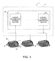
- Fig. 1 illustrates a schematic diagram of an entire configuration of an airflow control system 1 according to an embodiment of the present invention.
- the airflow control system 1 functioning as an air conditioning control system, is configured to control air conditioning in an indoor space by controlling airflow blown out of air conditioning blow-out panels 10.
- the airflow control system 1 is mainly composed of the air conditioning blow-out panels 10 (hereinafter referred to as blow-out panels 10) and an airflow control device 20.
- the airflow control device 20 is disposed such that it can communicate with the blow-out panels 10.
- the blow-out panels 10 are detachably attached to main bodies of air conditioning indoor units 50, respectively.
- a blow-out panel 10 and a main body of an air conditioning indoor unit 50 attached with the blow-out panel composes an air conditioning indoor unit.
- the air conditioning blow-out panels 10 may be configured to be directly attached/detached to/from the main bodies of the air conditioning indoor units, respectively (i.e., a so-called ceiling cassette type), or may be configured to be attached/detached to/from the main bodies of the air conditioning indoor units, respectively, through air transportation ducts and the like (i.e., a so-called duct type).
- the blow-out panels 10 include sensors 11, respectively. Although not illustrated in the figure, the sensors 11 in the air conditioning blow-out panels 10 may not be necessarily limited to single-type sensors. Each of the sensors 11 may be composed of a plurality of sensors such as: a sensor for detecting and outputting the number of, a position(s) of and an identification information of a person/people in the indoor space though a mobile phone(s) and an IC card(s); a temperature sensor; a humidity sensor; an infrared sensor; a CO2 sensor, an airflow direction and airflow volume sensor; and a luminosity sensor.
- a sensor for detecting and outputting the number of, a position(s) of and an identification information of a person/people in the indoor space though a mobile phone(s) and an IC card(s) a temperature sensor; a humidity sensor; an infrared sensor; a CO2 sensor, an airflow direction and airflow volume sensor; and a luminosity sensor.
- information obtained and outputted by the sensors include, for instance: the number of people in the indoor space; a position(s) of a person/people in the indoor space; identification information of a person/people in the indoor space; indoor temperature; indoor humidity; indoor air quality; a weather condition; a blow-out direction of the air conditioning blow-out panel; the airflow volume of the air conditioning blow-out panel; blow-out temperature of the air conditioning blow-out panel; and on/off states of peripheral devices.
- the sensors may not be attached to the blow-out panels 10.
- the sensors may be disposed in the main bodies of the air conditioning indoor units 50 or other places.
- each of the blow-out panels 10 includes blow-out ports 16 in four directions. As described below, each of the blow-out panels 10 is configured to control airflow by controlling flaps arranged in the inside of the blow-out ports 16, shutters for opening/closing the blow-out ports 16, other heretofore-known air flow volume regulation mechanism and the like.
- the airflow control device 20 includes a sensor information storage section 21 and a control command generation section 22.
- the sensor information storage section 21 is configured to obtain information from the sensors 11.
- the control command generation section 22 is configured to generate a control command based on the sensor information.
- the sensors 11 and the airflow control device 20 are disposed such that they can communicate with each other through wired/wireless connections, and form a network 2.
- the airflow control device 20 is installed into a computer including control units (e.g., a memory and a CPU). Additionally, the computer may be provided with a control unit for conducting other air conditioning control (e.g., air conditioning control for the indoor unit and the outdoor unit).
- the sensor information storage section 21 is configured to collectively obtain sensor information transmitted from the blow-out panels 10 and sensor information transmitted from other sensors, and is configured to store the sensor information with ID information for specifying areas where the sensor information was obtained (e.g., ID information of the blow-out panel 10 arranged in the area where the sensor information was obtained).
- the control command generation section 22 is configured to generate a control command based on the sensor information obtained from the sensor information storage section 21. Generation of the control command will be hereinafter explained in detail.
- the network formed in the airflow control system 1 of the present embodiment is assumed to be a local area network. However, it may be a distant network through a public telecommunication network or a private line and the like.
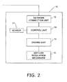
- Fig. 2 illustrates a schematic configuration of the interior of each of the blow-out panels 10.
- Each of the blow-out panels 10 includes the sensor 11, a network connection unit 12, a control unit 13, a driving unit 14 and a airflow regulation mechanism 15.
- the network connection unit 12 is configured to transmit the sensor information from the sensor 11 to the airflow control device 20.
- the network connection unit 12 is also configured to receive a control command from the control command generation section 22 and transmit it to the control unit 13.
- the control unit 13 is configured to control the driving unit 14 in accordance with the control command.
- the driving unit 14 is configured to drive the airflow regulation mechanism 15.
- the airflow regulation mechanism 15 mainly includes the flaps for regulating the airflow direction, the shutters for opening/closing the blow-out ports or a mechanism such as an airflow volume distribution mechanism (configured to increase/decrease the airflow volume by enlarging/reducing an opening area of the blow-out port) as disclosed in the specification of Japanese Patent No. 3807305 .
- an airflow direction is allowed to be determined by changing an angle of the flap disposed in the interior of the blow-out port 16.
- the airflow direction is allowed to be set with respect to the blow-out ports 16 of the blow-out panels 10, respectively.
- the airflow volume is allowed to be regulated by enlarging/reducing an opening area of a blow-out path.
- Fig. 3 illustrates a series of steps of processing to be executed by the airflow control system 1 according to the present embodiment with a flowchart.
- the sensors 11 of the blow-out panels 10 obtain sensor information, respectively (Step S101), and subsequently transmit the sensor information and ID information for specifying areas where the sensor information was obtained to the network 2 (Step S102).
- the sensor information storage section 21 stores the sensor information (Step S103).
- the control command generation section 22 generates a command for controlling the airflow direction and the airflow volume of each blow-out panel 10 based on the sensor information stored in the sensor information storage section 21 (Step S104), and transmits the control command to the blow-out panel 10 positioned in the corresponding area (Step S105).
- generation and transmission of a control command by the control command generation section 22 may be conducted at predetermined time intervals or in accordance with a predetermined demand signal inputted by a user.
- predetermined processing may be executed between Steps S103 and S104 for determining if the sensor information exceeds predetermined threshold, numeric range and the like. Then, when the sensor information exceeds the threshold or the range, a control command may be generated.
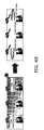
- FIGS. 4A and 4B illustrate examples of airflow control according to the present embodiment. Generation of a control command will be hereinafter explained along with the example.
- Fig. 4A illustrates control for preventing outflow of air-conditioned air to an absence area that has no people by regulating the airflow when a target space for air conditioning accommodates a person/people and simultaneously includes the absence area.
- the control is conducted as follows.
- the sensor information storage section 21 of the airflow control device 20 is configured to store the sensor information transmitted from the sensors of the plurality of the blow-out panels 10 arranged in the target space for air conditioning.
- the control command generation section 22 is configured to classify the air conditioning area into three areas (i.e., "absence area”, “presence area” and “adjacent area”) based on position information of a person/people in the target space that is part of the sensor information stored in the sensor information storage section 21.
- the absence area is defined as an area with no people.
- the adjacent area is defined as an area adjacent to the absence area, accommodating a person/people.
- the presence area is defined as an area accommodating a person/people excluding the adjacent area.
- the control command generation section 22 is configured to transmit a control command of inactivation (i.e., reduction of the airflow volume to zero) to the blow-out panel 10 arranged in the absence area. Additionally, the control command generation section 22 is configured to transmit a control command for setting an airflow direction toward the presence area to the blow-out panel 10 arranged in the adjacent area. With the configuration, it is possible to prevent outflow of the air-conditioned air to the absence area. In other words, it is possible to reduce energy consumed by unnecessary air conditioning.
- the airflow direction of the blow-out panel 10 arranged in the adjacent area may be set to be a downward direction, an obliquely-downward direction opposite to the presence area, or directions swinging between predetermined angles.
- the airflow volume of the blow-out panel 10 arranged in the adjacent area may be kept to the same as the airflow volume in the presence area.
- the airflow control makes it possible to prevent diffusion of the air-conditioned air to the absence area. Accordingly, it is possible to enhance comfortableness and energy saving.
- Fig. 4B illustrates control for eliminating temperature irregularity in the indoor space by generating airflow when the indoor space simultaneously includes a high-temperature part and a low-temperature part.
- the control command generation section 22 of the airflow control device 20 transmits control commands to the respective blow-out panels 10 and generate airflow for mixing the entire air in the indoor space.
- the airflow directions of the blow-out ports 16 are set to a predetermined circulation direction so as to entirely circulate the airflow along the walls of the indoor space, thereby eliminating temperature irregularity in the indoor space.
- temperature, humidity, air quality and position information of a person/people in the indoor space are obtained from the sensor information, and the control command generation section 22 determines if the control command should be generated based on the sensor information.
- a threshold or a predetermined numeric range is preliminarily set for temperature of the indoor space, humidity of the indoor space and air quality of the indoor space, for instance.
- the control command generation section 22 determines necessity of control and accordingly generates and transmits a control command.
- the airflow volume may be controlled under set conditions such as a weather condition, blow-out temperature of the air conditioning blow-out panel and on/off states of peripheral devices.
- the airflow control device 20 of the airflow control system 1 is configured to transmit the sensor information from the sensor information storage section 21 to the control command generation section 22.
- a controller 24 may be further provided between them.
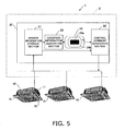
- an airflow control device 20 includes a sensor information storage section 21, a condition information generation section 23, a controller 24, and a control command generation section 22.
- the sensor information storage section 21 is configured to obtain information from sensors 11.
- the condition information generation section 23 is configured to generate condition information (as described later) based on the information from the sensor information storage section 21.
- the controller 24 is configured to display the condition information and allow a user to input information for a control command.
- the control command generation section 22 is configured to generate a control command based on the displayed input information.
- the condition information generation section 23 is configured to generate information of an indoor condition based on the sensor information stored in the sensor information storage section 21.
- the condition information indicates a condition (e.g., humidity and temperature) derived from the sensor information (e.g., the number of people in the indoor space and thermal environment).
- the controller 24 includes a display unit 24b (e.g., liquid-crystal display) and a touch-panel typed input unit 24a displaying icons and the like.
- the display unit 24b is configured to display condition information generated by the condition information generation section 23.
- the display unit 24b may be configured to display indoor temperature and humidity or may be configured to display a discomfort index calculated with a predetermined formula.
- the display unit 24b may be configured to display a picture or a sign for making a user intuitively understand the conditions.
- a target blow-out panel 10 to be controlled may be chosen by a user directly inputting the position of the target blow-out panel 10.
- the target blow-out panel 10 to be controlled may be set in accordance with a user's position specified by an input of the user information (e.g., a user ID).
- a screen of the display unit 24b and a form of the input unit 24a may not be limited to the above, and may have other configurations.
- the control command generation section 22 is configured to generate a control command based on the information inputted by a user through the controller 24.
- Step S111 each of the sensors 11 obtains sensor information.
- Step S 112 the sensor information is transmitted to the network together with ID information for specifying an area where the sensor information was obtained.
- Step S113 the sensor information storage section 21 stores the sensor information obtained.
- Step S114 the condition information generation section 23 generates condition information based on the sensor information thus stored and transmits it to the controller 24.
- Step S115 the controller 24 displays condition information.
- Step S116 information for generating a control command is inputted by a user based on the displayed condition information.
- Step S117 a command for controlling the airflow direction and the airflow volume of each of the blow-out panels 10 is generated.
- Step S118 the control command is transmitted to a target blow-out panel 10 to be controlled.
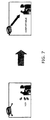
- Fig. 7 illustrates an example of the airflow control of the present modification.
- a control command is generated for producing a local airflow making the person feel airflow.
- the control command is transmitted to the target blow-out panel 10.
- the airflow volume and the airflow direction may be determined as follows. The comfortableness of a person in the indoor room and his/her adjacent person is estimated based on a variety of information such as distance and angle between the blow-out panel and the person in the indoor space, the human body heat storage amount of the person in the indoor space, existence/nonexistence of an adjacent person, temperature in the indoor space, and the present value of the airflow volume and the airflow direction.
- the airflow volume and the airflow direction are set such that the estimated values for the comfortableness are in predetermined ranges.
- the control command may be changed from hour to hour based on a period of time when the person receives airflow in the indoor space or variation in comfortableness.
- the human body heat storage amount of a person in the indoor space may be, for instance, derived from the time-series variation in position information of the person in the indoor space obtained by means of a GPS and the like.
- the condition information generation section 23 is configured to obtain temperature, humidity, air quality and position information of a person in the indoor space and the like based on the sensor information. Then, the condition information generation section 23 is configured to generate condition information based on the sensor information, and transmits it to the controller 24. For example, for generating the condition information, thresholds or predetermined numeric ranges are preliminarily set for temperature, humidity and air quality in the indoor space. The preliminarily-set thresholds or predetermined numeric ranges are compared with actual values of temperature, humidity and air quality in the indoor space. The condition information is generated based on the results of comparison. The controller 24 is configured to display information such as "hot” and "cold". In generating the condition information, a variety of conditions may be set, such as a weather condition, blow-out temperature of the air conditioning blow-out panel and on/off states of peripheral devices.
- the position information of a person in the indoor space may be comprehended by information transmitted from a personal computer, an IC card, a mobile phone and the like used by the person in the indoor space.
- the airflow control device 20 may be configured to preliminarily store ID information of the person in the indoor space and the airflow volume preferred by the person in the indoor space and the like as associated information. In this case, when the airflow control device 20 receives the ID information of the person in the indoor space, it may set the airflow volume to be the preferred airflow volume of the person in the indoor space, for instance.
- the controller 24 includes the input unit 24a and the display unit 24b.
- the input unit 24a is configured to directly receive an input of a control command
- the display unit 24b is configured to display condition information generated based on the sensor information.
- the airflow control system 1 according to the second modification of the present embodiment will be hereinafter explained.
- Sensor information stored in the sensor information storage section 21 of the airflow control device 20 of the present modification, includes outdoor temperature information.
- the outdoor temperature information is obtained by a predetermined outdoor temperature information obtainment means (e.g., a temperature sensor disposed outdoors and obtainment of weather information from a public meteorological institute).
- the control command generation section 22 of the airflow control device 20 is configured to obtain outdoor temperature information from the sensor information storage section 21.
- the control command generation section 22 is configured to generate a control command in accordance with the obtained outdoor temperature information. Examples of the control command will be hereinafter explained.
- a blow-out temperature regulation section 55 of the air conditioning indoor unit 50 is controlled in accordance with the aforementioned outdoor temperature information.
- the blow-out temperature regulation section 55 is configured to regulate blow-out temperature of the air conditioning indoor unit 50 by generating and transmitting a command regarding frequency of a compressor and opening/closing of a control valve and the like.
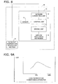
- coefficient of performance (COP) of an air conditioning apparatus generally reaches the peak when load factor of the air conditioning apparatus falls in the range of approximately 50-70%.
- COP coefficient of performance
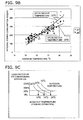
- Fig. 9B it is therefore possible to regulate the load factor of the air conditioning apparatus to be approximately 50-70% by increasing the blow-out temperature when the outdoor temperature is high.
- energy saving efficiency gets higher.
- the airflow control system 1 is capable of enhancing energy saving. Note that it is desirable to regulate the blow-out temperature such that the indoor temperature is in a range of a preset temperature of the air conditioning apparatus.
- control command generation section 22 is configured to generate a control command for increasing the blow-out temperature in accordance with an increase of the outdoor temperature in a cooling operation of the air conditioning apparatus.
- Fig. 9C is an example of the relations obtained by the measurement.
- Fig. 9C illustrates relations between the blow-out temperature and the load factor of the air conditioning apparatus in a cooling operation with respect to predetermined outdoor temperature levels (i.e., 30, 25 and 20 degrees Celsius).
- predetermined outdoor temperature levels i.e. 30, 25 and 20 degrees Celsius.
- the load factor of the air conditioning apparatus is approximately 50% under the setting of the blow out temperature of 20 degrees Celsius.
- the outdoor temperature is 25 degrees Celsius
- it is possible to set the load factor of the air conditioning apparatus to approximately 50% by setting the blow-out temperature to 18 degrees Celsius.
- the outdoor temperature is 20 degrees Celsius, it is possible to set the load factor of the air conditioning apparatus to approximately 50% by setting the blow-out temperature to 16 degrees Celsius.
- the control command generation section 22 refers to the relations between the stored blow-out temperature and the stored load factor of the air conditioning apparatus in accordance with the outdoor temperature. Based on the reference, the control command generation section 22 determines the blow-out temperature so as to set the load factor of the air conditioning apparatus to approximately 50%. The control command generation section 22 generates a control command based on the determination.
- the aforementioned control command is transmitted to the blow-out temperature regulation section 55, and the blow-out temperature regulation section 55 regulates the blow-out temperature.
- the airflow control system 1 is capable of conducting airflow control with better COP. Accordingly, the airflow control system 1 is capable of enhancing energy saving.
- the airflow control system 1 is configured to control the airflow volume of the blow-out panels 10 in accordance with the aforementioned outdoor temperature information.
- control command generation section 22 generates a control command for less airflow volume with a higher outdoor temperature when the air conditioning apparatus conducts a cooling operation by taking in the outdoor air.
- the control command generation section 22 generates a control command for more airflow volume with a lower outdoor temperature.
- the control command generation section 22 when the outdoor temperature is higher than the indoor temperature, the control command generation section 22 generates a control command for reducing the airflow by a predetermined volume.
- the control command generation section 22 is configured to generate a control command for increasing airflow by a predetermined volume. In this case, increase and decrease of the airflow volume are not limited to a predetermined amount.
- the airflow volume may be increased or decreased in accordance with difference between the outdoor temperature and the indoor temperature.
- the airflow control system 1 is capable of enhancing energy saving.
- the airflow control system 1 is capable of achieving similar working effects by conducting the opposite control in the heating operation.
- the aforementioned control command is transmitted to the control unit 13 through the network connection unit 12, and the control unit 13 controls the airflow volume through the driving unit 14 and the airflow regulation mechanism 15.
- the airflow control system 1 is capable of reducing the air conditioning load, and is thereby capable of enhancing energy saving.
- the present invention is useful as an air conditioning blow-out panel, an air conditioning control system and an air conditioning control method for achieving comfortableness and enhancing energy saving by conducting effective airflow control based on sensor information of an entire space.
Landscapes
- Engineering & Computer Science (AREA)
- Chemical & Material Sciences (AREA)
- Combustion & Propulsion (AREA)
- Mechanical Engineering (AREA)
- General Engineering & Computer Science (AREA)
- Human Computer Interaction (AREA)
- Physics & Mathematics (AREA)
- Fluid Mechanics (AREA)
- Air Conditioning Control Device (AREA)
Applications Claiming Priority (2)
| Application Number | Priority Date | Filing Date | Title |
|---|---|---|---|
| JP2007008567 | 2007-01-17 | ||
| PCT/JP2008/050536 WO2008088020A1 (fr) | 2007-01-17 | 2008-01-17 | Panneau de soufflerie de climatisation, système de commande de climatisation muni du panneau et procédé de commande de climatisation |
Publications (2)
| Publication Number | Publication Date |
|---|---|
| EP2105678A1 true EP2105678A1 (fr) | 2009-09-30 |
| EP2105678A4 EP2105678A4 (fr) | 2017-11-29 |
Family
ID=39636021
Family Applications (1)
| Application Number | Title | Priority Date | Filing Date |
|---|---|---|---|
| EP08703391.6A Withdrawn EP2105678A4 (fr) | 2007-01-17 | 2008-01-17 | Panneau de soufflerie de climatisation, système de commande de climatisation muni du panneau et procédé de commande de climatisation |
Country Status (7)
| Country | Link |
|---|---|
| US (1) | US20100101264A1 (fr) |
| EP (1) | EP2105678A4 (fr) |
| JP (1) | JP4952722B2 (fr) |
| KR (1) | KR20090106565A (fr) |
| CN (1) | CN101583830B (fr) |
| AU (1) | AU2008205868B2 (fr) |
| WO (1) | WO2008088020A1 (fr) |
Cited By (2)
| Publication number | Priority date | Publication date | Assignee | Title |
|---|---|---|---|---|
| WO2012120322A1 (fr) * | 2011-03-04 | 2012-09-13 | Carrier Corporation | Commande de poutres climatiques actives |
| EP3945257A1 (fr) * | 2020-07-30 | 2022-02-02 | LG Electronics Inc. | Épurateur d'air |
Families Citing this family (32)
| Publication number | Priority date | Publication date | Assignee | Title |
|---|---|---|---|---|
| JP4715947B2 (ja) * | 2009-05-01 | 2011-07-06 | ダイキン工業株式会社 | 空調システム |
| JP5316473B2 (ja) * | 2010-04-27 | 2013-10-16 | ダイキン工業株式会社 | 空気調和装置 |
| JP2011257072A (ja) * | 2010-06-09 | 2011-12-22 | Panasonic Electric Works Co Ltd | エネルギー管理装置 |
| JP5067474B2 (ja) * | 2010-12-16 | 2012-11-07 | ダイキン工業株式会社 | 空調システム |
| WO2012165558A1 (fr) * | 2011-06-03 | 2012-12-06 | シャープ株式会社 | Dispositif de commande et procédé de présentation |
| CN102679505B (zh) * | 2012-06-13 | 2014-04-23 | 重庆大学 | 房间温度控制方法 |
| TWI495831B (zh) * | 2012-11-15 | 2015-08-11 | Chang Hong I | Air conditioning air supply with dynamic flow adjustment |
| US20140278260A1 (en) | 2013-03-15 | 2014-09-18 | Leeo, Inc. | Environmental measurement display system and method |
| US20140278735A1 (en) | 2013-03-15 | 2014-09-18 | Leeo, Inc. | Environmental monitoring device |
| JP6170763B2 (ja) * | 2013-07-05 | 2017-07-26 | アズビル株式会社 | 表示装置および方法 |
| WO2015009350A1 (fr) | 2013-07-16 | 2015-01-22 | Leeo, Inc. | Dispositif électronique doté d'une surveillance de l'environnement |
| US9116137B1 (en) | 2014-07-15 | 2015-08-25 | Leeo, Inc. | Selective electrical coupling based on environmental conditions |
| EP2905584B2 (fr) | 2014-02-07 | 2020-08-26 | Blueair AB | Module capteur amovible pour dispositif de traitement d'air |
| US9213327B1 (en) | 2014-07-15 | 2015-12-15 | Leeo, Inc. | Selective electrical coupling based on environmental conditions |
| US9170625B1 (en) | 2014-07-15 | 2015-10-27 | Leeo, Inc. | Selective electrical coupling based on environmental conditions |
| US9372477B2 (en) | 2014-07-15 | 2016-06-21 | Leeo, Inc. | Selective electrical coupling based on environmental conditions |
| US9092060B1 (en) | 2014-08-27 | 2015-07-28 | Leeo, Inc. | Intuitive thermal user interface |
| US10078865B2 (en) | 2014-09-08 | 2018-09-18 | Leeo, Inc. | Sensor-data sub-contracting during environmental monitoring |
| US9445451B2 (en) | 2014-10-20 | 2016-09-13 | Leeo, Inc. | Communicating arbitrary attributes using a predefined characteristic |
| US10026304B2 (en) | 2014-10-20 | 2018-07-17 | Leeo, Inc. | Calibrating an environmental monitoring device |
| WO2016157384A1 (fr) * | 2015-03-30 | 2016-10-06 | 三菱電機株式会社 | Système de soufflage d'air |
| JP6542566B2 (ja) * | 2015-04-08 | 2019-07-10 | 日立ジョンソンコントロールズ空調株式会社 | 空気調和システム |
| US9801013B2 (en) | 2015-11-06 | 2017-10-24 | Leeo, Inc. | Electronic-device association based on location duration |
| US10805775B2 (en) | 2015-11-06 | 2020-10-13 | Jon Castor | Electronic-device detection and activity association |
| CN106152418A (zh) * | 2016-08-11 | 2016-11-23 | 合肥通用电源设备有限公司 | 一种基于人数的空调控制系统及方法 |
| JP7029918B2 (ja) * | 2017-09-29 | 2022-03-04 | シャープ株式会社 | 環境測定装置および環境測定システム |
| CN108759008B (zh) * | 2018-06-12 | 2020-09-04 | 广东美的暖通设备有限公司 | 空调的控制方法、装置及具有其的空调 |
| JP7272784B2 (ja) | 2018-12-04 | 2023-05-12 | ファナック株式会社 | 工場内環境制御システム |
| CN110925951A (zh) * | 2019-12-10 | 2020-03-27 | 西安冉科信息技术有限公司 | 一种中央空调的控制系统 |
| US20230258357A1 (en) * | 2020-01-14 | 2023-08-17 | Mitsubishi Electric Corporation | Control device and control method |
| US12164272B2 (en) | 2021-02-04 | 2024-12-10 | Abb Schweiz Ag | Virus control building management system |
| JPWO2024228267A1 (fr) * | 2023-05-02 | 2024-11-07 |
Family Cites Families (6)
| Publication number | Priority date | Publication date | Assignee | Title |
|---|---|---|---|---|
| US6079626A (en) * | 1996-01-16 | 2000-06-27 | Hartman; Thomas B. | Terminal unit with active diffuser |
| JP3807305B2 (ja) | 2001-12-28 | 2006-08-09 | ダイキン工業株式会社 | 空気調和機 |
| JP2004102653A (ja) * | 2002-09-10 | 2004-04-02 | Ntt Docomo Kansai Inc | 設備機器、有用情報作成システム、携帯端末自動制限システム、および携帯端末 |
| JP2004150731A (ja) * | 2002-10-31 | 2004-05-27 | Daikin Ind Ltd | 空気調和装置 |
| CN100473917C (zh) * | 2004-06-09 | 2009-04-01 | 空调技研工业株式会社 | 送风口装置的风向调节叶片 |
| JP2006183974A (ja) * | 2004-12-28 | 2006-07-13 | Sanki Eng Co Ltd | 空調用吹出気流自動調整装置と空調用吹出気流の制御方法 |
-
2008
- 2008-01-17 JP JP2008554080A patent/JP4952722B2/ja not_active Expired - Fee Related
- 2008-01-17 AU AU2008205868A patent/AU2008205868B2/en not_active Ceased
- 2008-01-17 WO PCT/JP2008/050536 patent/WO2008088020A1/fr not_active Ceased
- 2008-01-17 KR KR1020097015852A patent/KR20090106565A/ko not_active Ceased
- 2008-01-17 US US12/521,883 patent/US20100101264A1/en not_active Abandoned
- 2008-01-17 CN CN2008800023650A patent/CN101583830B/zh active Active
- 2008-01-17 EP EP08703391.6A patent/EP2105678A4/fr not_active Withdrawn
Non-Patent Citations (1)
| Title |
|---|
| See references of WO2008088020A1 * |
Cited By (2)
| Publication number | Priority date | Publication date | Assignee | Title |
|---|---|---|---|---|
| WO2012120322A1 (fr) * | 2011-03-04 | 2012-09-13 | Carrier Corporation | Commande de poutres climatiques actives |
| EP3945257A1 (fr) * | 2020-07-30 | 2022-02-02 | LG Electronics Inc. | Épurateur d'air |
Also Published As
| Publication number | Publication date |
|---|---|
| CN101583830A (zh) | 2009-11-18 |
| CN101583830B (zh) | 2012-02-22 |
| AU2008205868A1 (en) | 2008-07-24 |
| EP2105678A4 (fr) | 2017-11-29 |
| WO2008088020A1 (fr) | 2008-07-24 |
| AU2008205868B2 (en) | 2011-01-20 |
| US20100101264A1 (en) | 2010-04-29 |
| JPWO2008088020A1 (ja) | 2010-05-13 |
| JP4952722B2 (ja) | 2012-06-13 |
| KR20090106565A (ko) | 2009-10-09 |
Similar Documents
| Publication | Publication Date | Title |
|---|---|---|
| AU2008205868B2 (en) | Air conditioning blow-out panel, air conditioning control system including the same and air conditioning control method | |
| Han et al. | Energy-saving building system integration with a smart and low-cost sensing/control network for sustainable and healthy living environments: Demonstration case study | |
| CN102252408B (zh) | 用于环境控制系统中电动排气口盖的系统和方法 | |
| EP2985539B1 (fr) | Système de climatisation | |
| EP2835594B1 (fr) | Dispositif de commande d'unite de conditionnement d'air et programme de commande d'unite de conditionnement d'air | |
| WO2019034123A1 (fr) | Procédé de commande de climatiseur intelligent et climatiseur intelligent | |
| US20100250009A1 (en) | Control of conditioned environment by remote sensor | |
| US20180135879A1 (en) | Air-conditioning control system | |
| CN108375173A (zh) | 空调器中室内机的导风板的控制方法、空调器 | |
| CA3205326A1 (en) | Integrated thermal comfort control system | |
| EP3282198B1 (fr) | Climatiseur | |
| EP4006439B1 (fr) | Système de commande de climatisation | |
| KR101659301B1 (ko) | 난방비를 고려한 난방 제어 시스템 | |
| JPWO2021019761A1 (ja) | 空気調和システムおよびシステム制御装置 | |
| JP7004508B2 (ja) | 空調制御装置、空気調和機、空調システム、空調制御方法およびプログラム | |
| US20220003450A1 (en) | Personal workspace air supply and comfort conditioning unit | |
| JP2020008246A (ja) | 空気調和システム、空気調和システムの機種選定方法、空気調和システムの機種選定装置および空気調和システムの機種選定システム | |
| KR102206461B1 (ko) | 공기조화기 시스템 및 그 동작방법 | |
| JP2013221725A (ja) | 建物の温度調整システム | |
| US20250362042A1 (en) | Replacement air-conditioning system and information processing method | |
| KR20140103194A (ko) | 온도 맞춤형 공기조화 시스템 및 그 작동방법 | |
| JP2023161656A (ja) | 空調システム | |
| EP3282199B1 (fr) | Climatiseur | |
| CN119137426A (zh) | 传感器配置决定装置以及传感器配置决定方法 | |
| KR20130053936A (ko) | 공기 조화기와, 이를 포함한 공기 조화 시스템, 및 조명 시스템 |
Legal Events
| Date | Code | Title | Description |
|---|---|---|---|
| PUAI | Public reference made under article 153(3) epc to a published international application that has entered the european phase |
Free format text: ORIGINAL CODE: 0009012 |
|
| 17P | Request for examination filed |
Effective date: 20090714 |
|
| AK | Designated contracting states |
Kind code of ref document: A1 Designated state(s): AT BE BG CH CY CZ DE DK EE ES FI FR GB GR HR HU IE IS IT LI LT LU LV MC MT NL NO PL PT RO SE SI SK TR |
|
| DAX | Request for extension of the european patent (deleted) | ||
| RA4 | Supplementary search report drawn up and despatched (corrected) |
Effective date: 20171027 |
|
| RIC1 | Information provided on ipc code assigned before grant |
Ipc: F24F 11/02 20060101AFI20171023BHEP Ipc: F24F 11/00 20060101ALI20171023BHEP Ipc: F24F 1/00 20110101ALI20171023BHEP |
|
| STAA | Information on the status of an ep patent application or granted ep patent |
Free format text: STATUS: EXAMINATION IS IN PROGRESS |
|
| 17Q | First examination report despatched |
Effective date: 20200508 |
|
| RAP3 | Party data changed (applicant data changed or rights of an application transferred) |
Owner name: DAIKIN INDUSTRIES, LTD. |
|
| P01 | Opt-out of the competence of the unified patent court (upc) registered |
Effective date: 20230525 |
|
| REG | Reference to a national code |
Ref country code: DE Ref legal event code: R079 Free format text: PREVIOUS MAIN CLASS: F24F0011020000 Ipc: F24F0011300000 |
|
| RIC1 | Information provided on ipc code assigned before grant |
Ipc: F24F 11/74 20180101ALI20230825BHEP Ipc: F24F 1/0047 20190101ALI20230825BHEP Ipc: F24F 11/54 20180101ALI20230825BHEP Ipc: F24F 11/56 20180101ALI20230825BHEP Ipc: F24F 120/10 20180101ALI20230825BHEP Ipc: F24F 110/00 20180101ALI20230825BHEP Ipc: F24F 11/79 20180101ALI20230825BHEP Ipc: F24F 11/77 20180101ALI20230825BHEP Ipc: F24F 11/30 20180101AFI20230825BHEP |
|
| GRAP | Despatch of communication of intention to grant a patent |
Free format text: ORIGINAL CODE: EPIDOSNIGR1 |
|
| STAA | Information on the status of an ep patent application or granted ep patent |
Free format text: STATUS: GRANT OF PATENT IS INTENDED |
|
| INTG | Intention to grant announced |
Effective date: 20231023 |
|
| STAA | Information on the status of an ep patent application or granted ep patent |
Free format text: STATUS: THE APPLICATION IS DEEMED TO BE WITHDRAWN |
|
| 18D | Application deemed to be withdrawn |
Effective date: 20240305 |