EP2106497B1 - Einsatz für eine zylinderlaufbuchse oder einem zylinder eines verbrennungsmotors - Google Patents
Einsatz für eine zylinderlaufbuchse oder einem zylinder eines verbrennungsmotors Download PDFInfo
- Publication number
- EP2106497B1 EP2106497B1 EP07722002.8A EP07722002A EP2106497B1 EP 2106497 B1 EP2106497 B1 EP 2106497B1 EP 07722002 A EP07722002 A EP 07722002A EP 2106497 B1 EP2106497 B1 EP 2106497B1
- Authority
- EP
- European Patent Office
- Prior art keywords
- cylinder
- cylinder liner
- insert
- internal combustion
- combustion engine
- Prior art date
- Legal status (The legal status is an assumption and is not a legal conclusion. Google has not performed a legal analysis and makes no representation as to the accuracy of the status listed.)
- Not-in-force
Links
Images

Classifications
-
- F—MECHANICAL ENGINEERING; LIGHTING; HEATING; WEAPONS; BLASTING
- F02—COMBUSTION ENGINES; HOT-GAS OR COMBUSTION-PRODUCT ENGINE PLANTS
- F02B—INTERNAL-COMBUSTION PISTON ENGINES; COMBUSTION ENGINES IN GENERAL
- F02B77/00—Component parts, details or accessories, not otherwise provided for
- F02B77/04—Cleaning of, preventing corrosion or erosion in, or preventing unwanted deposits in, combustion engines
-
- F—MECHANICAL ENGINEERING; LIGHTING; HEATING; WEAPONS; BLASTING
- F16—ENGINEERING ELEMENTS AND UNITS; GENERAL MEASURES FOR PRODUCING AND MAINTAINING EFFECTIVE FUNCTIONING OF MACHINES OR INSTALLATIONS; THERMAL INSULATION IN GENERAL
- F16J—PISTONS; CYLINDERS; SEALINGS
- F16J10/00—Engine or like cylinders; Features of hollow, e.g. cylindrical, bodies in general
- F16J10/02—Cylinders designed to receive moving pistons or plungers
- F16J10/04—Running faces; Liners
-
- F—MECHANICAL ENGINEERING; LIGHTING; HEATING; WEAPONS; BLASTING
- F02—COMBUSTION ENGINES; HOT-GAS OR COMBUSTION-PRODUCT ENGINE PLANTS
- F02F—CYLINDERS, PISTONS OR CASINGS, FOR COMBUSTION ENGINES; ARRANGEMENTS OF SEALINGS IN COMBUSTION ENGINES
- F02F1/00—Cylinders; Cylinder heads
-
- F—MECHANICAL ENGINEERING; LIGHTING; HEATING; WEAPONS; BLASTING
- F02—COMBUSTION ENGINES; HOT-GAS OR COMBUSTION-PRODUCT ENGINE PLANTS
- F02F—CYLINDERS, PISTONS OR CASINGS, FOR COMBUSTION ENGINES; ARRANGEMENTS OF SEALINGS IN COMBUSTION ENGINES
- F02F1/00—Cylinders; Cylinder heads
- F02F1/02—Cylinders; Cylinder heads having cooling means
- F02F1/10—Cylinders; Cylinder heads having cooling means for liquid cooling
- F02F1/16—Cylinder liners of wet type
-
- F—MECHANICAL ENGINEERING; LIGHTING; HEATING; WEAPONS; BLASTING
- F02—COMBUSTION ENGINES; HOT-GAS OR COMBUSTION-PRODUCT ENGINE PLANTS
- F02F—CYLINDERS, PISTONS OR CASINGS, FOR COMBUSTION ENGINES; ARRANGEMENTS OF SEALINGS IN COMBUSTION ENGINES
- F02F1/00—Cylinders; Cylinder heads
- F02F1/02—Cylinders; Cylinder heads having cooling means
- F02F1/10—Cylinders; Cylinder heads having cooling means for liquid cooling
- F02F1/16—Cylinder liners of wet type
- F02F1/166—Spacer decks
-
- F—MECHANICAL ENGINEERING; LIGHTING; HEATING; WEAPONS; BLASTING
- F02—COMBUSTION ENGINES; HOT-GAS OR COMBUSTION-PRODUCT ENGINE PLANTS
- F02F—CYLINDERS, PISTONS OR CASINGS, FOR COMBUSTION ENGINES; ARRANGEMENTS OF SEALINGS IN COMBUSTION ENGINES
- F02F1/00—Cylinders; Cylinder heads
- F02F1/18—Other cylinders
-
- F—MECHANICAL ENGINEERING; LIGHTING; HEATING; WEAPONS; BLASTING
- F02—COMBUSTION ENGINES; HOT-GAS OR COMBUSTION-PRODUCT ENGINE PLANTS
- F02F—CYLINDERS, PISTONS OR CASINGS, FOR COMBUSTION ENGINES; ARRANGEMENTS OF SEALINGS IN COMBUSTION ENGINES
- F02F1/00—Cylinders; Cylinder heads
- F02F2001/006—Cylinders; Cylinder heads having a ring at the inside of a liner or cylinder for preventing the deposit of carbon oil particles, e.g. oil scrapers
Definitions
- the present invention relates to a cylinder liner or a cylinder of an internal combustion engine, with an insert which narrows the inner diameter of the cylinder liner or the cylinder, wherein the insert is formed as an open, prestressed ring with a ring joint and held such that the radial surface pressure approximately equal to the circumference is.
- Such an insert is used to strip off the attached to the top land of a run in the cylinder liner or in the cylinder piston coal and to avoid contact of the carbon with the running surfaces of the cylinder liner or the cylinder.
- a combined device consisting of a sealing element to the cylinder head and an oil scraper is in the US-A 4,474,147 described.
- the closed ring insert is made angled towards the cylinder head.
- Another such use is from the DE 35 43 668 A1 known.
- the trained as a deep-drawn part or rotary insert is held by a radial collar which is pressed from the cylinder head to the cylinder crankcase.
- Such inserts are difficult to manufacture and fit in the liner due to the tight tolerances in manufacturing and assembly and therefore not optimally suited for mass production.
- the object of the present invention is to provide a cylinder liner or a cylinder of an internal combustion engine, which is simple and inexpensive to manufacture and assemble, while achieving a reliable effect and is widely used.
- the cylinder liner or cylinder has a circumferential fold provided in the upper end surface of the cylinder liner or cylinder, that the insert has a radially extending peripheral flange located in the circumferential fold, and that the Ratio of the thickness of the annular wall to the inner diameter of the cylinder liner or the cylinder is between 0.001 and 0.02.
- the invention further relates to a cylinder crankcase for an internal combustion engine and an internal combustion engine, the at least one inventive Have cylinder liner or at least one cylinder according to the invention.
- the invention furthermore relates to a method for producing a cylinder liner or a cylinder according to the invention.
- the inventive method is characterized in that a strip is punched with a defined width of a sheet metal part, whose one longitudinal edge is folded to form a radially extending circumferential flange and then formed into an open, prestressed ring with a ring impact, which then in the cylinder liner or is inserted into the cylinder, wherein the radially extending circumferential flange is received in a circumferential fold which is provided in the upper end face of the cylinder liner or the cylinder.
- the inventive device or cylinder according to the invention is characterized by the combination of a circumferential fold in its end face and an insert with a radially extending circumferential flange. Since only the peripheral flange of the insert is received in the circumferential fold of the cylinder liner or the cylinder, no further recess, in particular in the running surface of the cylinder liner or the cylinder is required. Thus, the cylinder liner or the cylinder according to the invention undergoes no impairment in its stability and its tribological properties.
- the insert is shaped and dimensioned to be held in the cylinder liner or cylinder alone by radially outward acting forces.
- the outer diameter of the insert should be such that it is pressed in the region of the cylinder liner or the cylinder in which it is to be mounted with a circumferentially approximately equal radial surface pressure to the inner surface of the cylinder liner or the cylinder and axially in the as circumferential fold trained recess is guided.
- the embodiments for use include a ratio of thickness d of the annular wall to cylinder diameter D between 0.001 and 0.02.
- the insert is held very securely in the cylinder liner according to the invention or in the cylinder according to the invention also in the radial direction, since the radial surface pressure is circumferentially approximately the same when inserted in the cylinder or in the cylinder liner state.
- This design principle allows for use much smaller sizes than previously possible.
- the wall thickness of the insert can be reduced significantly over the prior art.
- the stability of the cylinder liner or the cylinder is maintained, because the wall of the cylinder liner or the cylinder is not weakened by a groove.
- the reduced size of the insert also allows the use not only in large diesel engines for commercial vehicles, but in virtually all engine types including car engines and small engines such as two-cylinder engines.
- the cylinder liner or cylinder according to the invention can be easily and inexpensively manufactured and conveniently mounted, in particular with the method according to the invention, the tolerances can be dimensioned so that a series production is possible and also economical.
- a ratio of the thickness (d) of the annular wall to the inner diameter (D) of the cylinder liner or cylinder of preferably between 0.003 and 0.01 has been found to be particularly practicable.
- the ring impact preferably has a defined shock play, so that during operation any thermal expansion that may occur can be compensated.
- a thickness (d) of the annular wall of the insert of, for example. 0.5 mm to 0.8 mm has proved to be advantageous.
- the insert according to the invention can be produced in particular from sheet metal, since this material can be punched particularly easily.
- An advantageous development of the internal combustion engine according to the invention provides that the piston arranged in the cylinder liner or the cylinder has a recess along its land, into which the insert protrudes.
- the Figures 1 and 2 show an embodiment of an insert 110 for a cylinder liner according to the invention or a cylinder according to the invention.
- the insert 110 is in the exemplary embodiment, a stamped part of a steel sheet having a thickness d of the annular wall of 0.4mm to 0.7mm.
- the insert 110 is made in the embodiment for a cylinder liner or a cylinder with an inner diameter of 130mm.
- the insert 110 has a ring impact 111. In the assembled state, the ring impact 111 is dimensioned so that it is not completely closed, but a certain amount of shock S remains, so that the insert 110 remains energized even during thermal expansion during operation.
- the mutually facing butt ends 112, 113 of the annular joint 111 extend at a defined angle W parallel to each other (see. FIG. 2 ).
- a closed contour of the insert 110 is achieved, so that the top land of the piston guided in the cylinder liner or in the cylinder is freed from coal over its entire lateral surface as far as possible.
- FIG. 3 shows the insert 110 FIG. 1 in untensioned and tensioned state, which was omitted for reasons of clarity on the representation of the flange.
- a sheet metal strip is punched according to the method of the invention from a steel sheet with a wall thickness of 0.8 mm, whose one longitudinal edge is folded into a flange 114. Then the sheet metal strip is formed into an open prestressed ring.
- the unstressed ring is provided with the reference numeral 110a.
- a defined mouth width M of 20mm is set in the embodiment.
- the outer shape is designed so that over the circumference of the built-in insert 110 results in a uniform surface pressure.
- FIG. 4 shows the insert 110 with its flange 114 according to FIG. 1 in assembled condition.
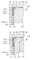
- FIG. 4 shows a section of an internal combustion engine 230 with a Cylinder crankcase 131 and a cylinder head 132. Between the cylinder crankcase 131 and the cylinder head 132, a cylinder head gasket 135 is inserted. Cylinder liners 220 are received in cylinder bores of the cylinder crankcase 131, in the interior 222 of which a piston 233 is guided. The piston 233 is provided with piston rings 134 which seal the combustion chamber (not shown). Above the piston rings 134 is the circumferential top land 236 of the piston 233.
- the insert 110 is received with its flange 114 only in a circumferential fold 223 which is provided in the upper, the cylinder head 132 facing end face of the cylinder liner 220.
- the insert 110 is held in the inner surface of the cylinder liner 220 by external radial forces.
- the insert 110 protrudes into a recess 237 in the top land 236 of the piston 233.
- the depth of the recess 237 is 0.4 mm.
- the insert 110 is disposed in the top dead center area 221 of the piston 233 in the cylinder liner 220, i. in the area of the movement reversal of the piston 233 during operation.
- FIG. 5 shows an embodiment in which the cylinder liner 220 is omitted, however, the same aforementioned conditions as explained FIG. 4 for a cylinder of an internal combustion engine 330 with a cylinder crankcase 331 apply.
Landscapes
- Engineering & Computer Science (AREA)
- General Engineering & Computer Science (AREA)
- Chemical & Material Sciences (AREA)
- Combustion & Propulsion (AREA)
- Mechanical Engineering (AREA)
- Cylinder Crankcases Of Internal Combustion Engines (AREA)
- Pistons, Piston Rings, And Cylinders (AREA)
Applications Claiming Priority (2)
| Application Number | Priority Date | Filing Date | Title |
|---|---|---|---|
| DE102006060330A DE102006060330A1 (de) | 2006-12-20 | 2006-12-20 | Einsatz für eine Zylinderlaufbuchse oder einem Zylinder eines Verbrennungsmotors |
| PCT/DE2007/000427 WO2008074277A1 (de) | 2006-12-20 | 2007-03-08 | Einsatz für eine zylinderlaufbuchse oder einem zylinder eines verbrennungsmotors |
Publications (2)
| Publication Number | Publication Date |
|---|---|
| EP2106497A1 EP2106497A1 (de) | 2009-10-07 |
| EP2106497B1 true EP2106497B1 (de) | 2016-11-02 |
Family
ID=38461714
Family Applications (1)
| Application Number | Title | Priority Date | Filing Date |
|---|---|---|---|
| EP07722002.8A Not-in-force EP2106497B1 (de) | 2006-12-20 | 2007-03-08 | Einsatz für eine zylinderlaufbuchse oder einem zylinder eines verbrennungsmotors |
Country Status (7)
| Country | Link |
|---|---|
| US (1) | US7484493B2 (ko) |
| EP (1) | EP2106497B1 (ko) |
| JP (1) | JP2010513776A (ko) |
| KR (1) | KR101373971B1 (ko) |
| BR (1) | BRPI0720844A2 (ko) |
| DE (1) | DE102006060330A1 (ko) |
| WO (1) | WO2008074277A1 (ko) |
Families Citing this family (22)
| Publication number | Priority date | Publication date | Assignee | Title |
|---|---|---|---|---|
| US7958814B2 (en) | 2008-03-26 | 2011-06-14 | General Electic Company | Power assembly for internal combustion engine with welded-in piston scraper |
| SE534911C2 (sv) * | 2010-06-16 | 2012-02-14 | Scania Cv Ab | Arrangemang i en förbränningsmotor |
| KR101156034B1 (ko) | 2010-07-15 | 2012-06-18 | 한국과학기술원 | 전기 자동차를 이용하는 운송 시스템의 급집전장치 설계 방법 및 장치 |
| EP2535540B1 (de) | 2011-06-16 | 2016-07-20 | Wärtsilä Switzerland Ltd. | Einsatz für einen Zylinder einer Brennkraftmaschine |
| TWM424412U (en) * | 2011-11-03 | 2012-03-11 | Fuko Inc | Telescopic rod positioning device with elastic retention component |
| US9771861B2 (en) | 2014-09-09 | 2017-09-26 | Avl Powertrain Engineering, Inc. | Opposed piston two-stroke engine with thermal barrier |
| US20160097340A1 (en) * | 2014-10-03 | 2016-04-07 | Caterpillar Inc. | Cylinder liner assembly having air gap insulation |
| DE102015003039A1 (de) | 2015-03-10 | 2016-09-15 | Mahle International Gmbh | Anordnung für einen Verbrennungsmotor |
| US9845764B2 (en) * | 2015-03-31 | 2017-12-19 | Achates Power, Inc. | Cylinder liner for an opposed-piston engine |
| JP2016211396A (ja) * | 2015-04-30 | 2016-12-15 | トヨタ自動車株式会社 | 内燃機関 |
| US10156202B2 (en) | 2016-03-04 | 2018-12-18 | Achates Power, Inc. | Barrier ring and assembly for a cylinder of an opposed-piston engine |
| EP3423693B1 (en) * | 2016-03-04 | 2021-02-17 | Wärtsilä Finland Oy | Cylinder liner and anti-polishing ring |
| US9938925B2 (en) * | 2016-05-16 | 2018-04-10 | Caterpillar Inc. | Cylinder liner with chamfer and anti-polishing cuff |
| DE102016007727A1 (de) * | 2016-06-23 | 2017-12-28 | Man Truck & Bus Ag | Brennkraftmaschine, insbesondere Hubkolben-Brennkraftmaschine |
| DE102016007992A1 (de) * | 2016-06-30 | 2018-01-04 | Hartwig Groeneveld | Quadrokolben 2 |
| EP3724479B1 (en) * | 2017-12-14 | 2026-04-22 | Cummins Inc. | Antipolishing ring |
| DE102019105613B4 (de) * | 2019-03-06 | 2020-09-24 | Federal-Mogul Burscheid Gmbh | Einrichtung zum abdichten eines brennraums eines verbrennungsmotors |
| CN111140397B (zh) * | 2019-12-24 | 2021-08-20 | 潍柴动力股份有限公司 | 发动机活塞以及发动机 |
| EP4158178A4 (en) | 2020-05-27 | 2024-10-30 | Cummins, Inc. | ANTI-POLISHER RING FOR AN ENGINE CYLINDER |
| US11428189B1 (en) * | 2021-05-12 | 2022-08-30 | Caterpillar Inc. | Piston bowl geometry, cuff and top land interaction for reduced hydrocarbons, improved combustion efficiency, and piston temperature |
| US11898488B2 (en) | 2021-05-12 | 2024-02-13 | Caterpillar Inc. | Piston bowl geometry, cuff and top land interaction for reduced hydrocarbons, improved combustion efficiency, and piston temperature |
| CN118934317A (zh) * | 2024-08-13 | 2024-11-12 | 一汽解放汽车有限公司 | 一种发动机气缸密封结构 |
Family Cites Families (18)
| Publication number | Priority date | Publication date | Assignee | Title |
|---|---|---|---|---|
| DE262939C (ko) * | 1911-12-02 | 1913-07-28 | ||
| US3489130A (en) | 1968-01-10 | 1970-01-13 | Sealed Power Corp | Piston and cylinder construction |
| US3476099A (en) * | 1968-02-26 | 1969-11-04 | Int Harvester Co | Head,gasket,and protector assembly and method |
| US4189161A (en) * | 1978-08-28 | 1980-02-19 | Muskegon Piston Ring Company | Bi-directional ring gap seal |
| US4474147A (en) | 1981-12-10 | 1984-10-02 | Mack Trucks, Inc. | Combined fire ring and carbon scraping insert |
| JPS58178441U (ja) * | 1982-05-24 | 1983-11-29 | 日産自動車株式会社 | 自動車用内燃機関のピストンリング装置 |
| JPS59126158U (ja) * | 1983-02-12 | 1984-08-24 | 株式会社リケン | 往復動内燃機関用ピストン |
| DE3543668A1 (de) * | 1985-12-11 | 1987-06-19 | Man Nutzfahrzeuge Gmbh | Zylinderlaufbuchse fuer hubkolben-verbrennungsmotoren |
| US4848212A (en) * | 1986-04-24 | 1989-07-18 | Mazda Motor Corporation | Internal combustion engine piston with two compression rings having reduced oil consumption |
| US5033426A (en) * | 1990-08-22 | 1991-07-23 | Cummins Engine Company, Inc. | Radial combustion seal |
| FR2666628B1 (fr) * | 1990-09-06 | 1994-09-16 | Melchior Jean | Dispositif d'etancheite entre la culasse et le cylindre d'une machine alternative a compression de fluide gazeux. |
| JPH04295166A (ja) * | 1991-03-26 | 1992-10-20 | Sanshin Ind Co Ltd | 船外機 |
| DK174074B1 (da) * | 1995-07-07 | 2002-05-21 | Man B & W Diesel As | Forbrændingsmotor med en koksskrabningsring i en cylinder |
| DE19703530C1 (de) * | 1997-01-31 | 1998-10-08 | Mtu Friedrichshafen Gmbh | Zylinderlaufbuchse mit einer Verengung der Zylinderbohrung und Verfahren zur Herstellung einer Zylinderlaufbuchse |
| FR2763362A1 (fr) | 1997-05-13 | 1998-11-20 | Semt Pielstick | Dispositif de raclage de la tete d'un piston |
| DE19811780C1 (de) | 1998-03-18 | 1999-08-26 | Daimler Chrysler Ag | Zylinderkurbelgehäuse für eine Brennkraftmaschine mit Zylinderräumen |
| US6536385B1 (en) * | 1999-03-17 | 2003-03-25 | Sanshin Kogyo Kabushiki Kaisha | Piston ring |
| DE10321034B3 (de) * | 2003-05-10 | 2005-01-13 | Daimlerchrysler Ag | Hubkolbenbrennkraftmaschine |
-
2006
- 2006-12-20 DE DE102006060330A patent/DE102006060330A1/de not_active Withdrawn
-
2007
- 2007-03-08 JP JP2009541744A patent/JP2010513776A/ja active Pending
- 2007-03-08 WO PCT/DE2007/000427 patent/WO2008074277A1/de not_active Ceased
- 2007-03-08 BR BRPI0720844-8A patent/BRPI0720844A2/pt not_active Application Discontinuation
- 2007-03-08 EP EP07722002.8A patent/EP2106497B1/de not_active Not-in-force
- 2007-03-08 KR KR1020097014098A patent/KR101373971B1/ko not_active Expired - Fee Related
- 2007-04-18 US US11/787,973 patent/US7484493B2/en active Active
Also Published As
| Publication number | Publication date |
|---|---|
| JP2010513776A (ja) | 2010-04-30 |
| EP2106497A1 (de) | 2009-10-07 |
| KR101373971B1 (ko) | 2014-03-12 |
| DE102006060330A1 (de) | 2008-06-26 |
| US20080150237A1 (en) | 2008-06-26 |
| BRPI0720844A2 (pt) | 2013-01-15 |
| US7484493B2 (en) | 2009-02-03 |
| KR20090091802A (ko) | 2009-08-28 |
| WO2008074277A1 (de) | 2008-06-26 |
Similar Documents
| Publication | Publication Date | Title |
|---|---|---|
| EP2106497B1 (de) | Einsatz für eine zylinderlaufbuchse oder einem zylinder eines verbrennungsmotors | |
| EP0547306B1 (de) | Deckel für Brennkraftmaschinen | |
| DE112009000466T5 (de) | Aufhängungsaxiallagervorrichtung und Federbein | |
| DE69017285T2 (de) | Kegelstumpfförmiges Ventilschaft-Dichtungselement. | |
| EP2683927B1 (de) | Nadelhülse, insbesondere zur schwenklagerung der drosselklappenwelle einer regeleinrichtung zur abgasrückführung an brennkraftmaschinen | |
| DE602004000959T2 (de) | Ringdichtung für Fluidtransferverbindung und Verbindung mit einer solchen Dichtung | |
| DE2030487A1 (de) | Abdichtung fur einen flachen, mit einer Öffnung versehenen Körperteil | |
| DE10325914B4 (de) | Kolben für einen Verbrennungsmotor | |
| DE3215709C2 (ko) | ||
| DE102012014192A1 (de) | Kolben für einen Verbrennungsmotor | |
| EP2138745B1 (de) | Zylinderkopfdichtung | |
| DE19808483A1 (de) | Ölabstreifkolbenring | |
| EP0380770A1 (de) | Ventilschaftabdichtung | |
| DE102007048361B4 (de) | Reparatursatz für Kurbelwellenzapfen | |
| DE69500470T2 (de) | Hochleistungsluftfilteranordnung | |
| DE19523825A1 (de) | Metallische Flachdichtung | |
| DE19822143C5 (de) | Zylinderkopfdichtung | |
| DE60201800T2 (de) | Lagermodul für Abgasrückführsteuerventil | |
| DE102020003214A1 (de) | Ventilschaftdichtung für eine Verbrennungskraftmaschine eines Kraftfahrzeugs | |
| DE202021101256U1 (de) | Ventilschaftdichtung und -anordnung | |
| DE2736599A1 (de) | Zylinderkopfdichtung | |
| DE4221760A1 (de) | Deckel fuer brennkraftmaschinen | |
| DE19901284C1 (de) | Ölabstreifkolbenring sowie Verfahren zum Einbau eines Ölabstreifkolbenringes | |
| DE102009059657A1 (de) | Kolben-Kolbenring-Anordnung | |
| DE19925278C2 (de) | Ölabstreifkolbenring |
Legal Events
| Date | Code | Title | Description |
|---|---|---|---|
| PUAI | Public reference made under article 153(3) epc to a published international application that has entered the european phase |
Free format text: ORIGINAL CODE: 0009012 |
|
| 17P | Request for examination filed |
Effective date: 20090717 |
|
| AK | Designated contracting states |
Kind code of ref document: A1 Designated state(s): AT BE BG CH CY CZ DE DK EE ES FI FR GB GR HU IE IS IT LI LT LU LV MC MT NL PL PT RO SE SI SK TR |
|
| 17Q | First examination report despatched |
Effective date: 20091014 |
|
| DAX | Request for extension of the european patent (deleted) | ||
| GRAP | Despatch of communication of intention to grant a patent |
Free format text: ORIGINAL CODE: EPIDOSNIGR1 |
|
| INTG | Intention to grant announced |
Effective date: 20160309 |
|
| GRAS | Grant fee paid |
Free format text: ORIGINAL CODE: EPIDOSNIGR3 |
|
| GRAA | (expected) grant |
Free format text: ORIGINAL CODE: 0009210 |
|
| AK | Designated contracting states |
Kind code of ref document: B1 Designated state(s): AT BE BG CH CY CZ DE DK EE ES FI FR GB GR HU IE IS IT LI LT LU LV MC MT NL PL PT RO SE SI SK TR |
|
| REG | Reference to a national code |
Ref country code: GB Ref legal event code: FG4D Free format text: NOT ENGLISH |
|
| REG | Reference to a national code |
Ref country code: AT Ref legal event code: REF Ref document number: 842094 Country of ref document: AT Kind code of ref document: T Effective date: 20161115 Ref country code: CH Ref legal event code: EP |
|
| REG | Reference to a national code |
Ref country code: IE Ref legal event code: FG4D Free format text: LANGUAGE OF EP DOCUMENT: GERMAN |
|
| REG | Reference to a national code |
Ref country code: DE Ref legal event code: R096 Ref document number: 502007015222 Country of ref document: DE |
|
| PG25 | Lapsed in a contracting state [announced via postgrant information from national office to epo] |
Ref country code: LV Free format text: LAPSE BECAUSE OF FAILURE TO SUBMIT A TRANSLATION OF THE DESCRIPTION OR TO PAY THE FEE WITHIN THE PRESCRIBED TIME-LIMIT Effective date: 20161102 |
|
| REG | Reference to a national code |
Ref country code: NL Ref legal event code: MP Effective date: 20161102 |
|
| REG | Reference to a national code |
Ref country code: LT Ref legal event code: MG4D |
|
| PG25 | Lapsed in a contracting state [announced via postgrant information from national office to epo] |
Ref country code: SE Free format text: LAPSE BECAUSE OF FAILURE TO SUBMIT A TRANSLATION OF THE DESCRIPTION OR TO PAY THE FEE WITHIN THE PRESCRIBED TIME-LIMIT Effective date: 20161102 Ref country code: GR Free format text: LAPSE BECAUSE OF FAILURE TO SUBMIT A TRANSLATION OF THE DESCRIPTION OR TO PAY THE FEE WITHIN THE PRESCRIBED TIME-LIMIT Effective date: 20170203 Ref country code: NL Free format text: LAPSE BECAUSE OF FAILURE TO SUBMIT A TRANSLATION OF THE DESCRIPTION OR TO PAY THE FEE WITHIN THE PRESCRIBED TIME-LIMIT Effective date: 20161102 Ref country code: LT Free format text: LAPSE BECAUSE OF FAILURE TO SUBMIT A TRANSLATION OF THE DESCRIPTION OR TO PAY THE FEE WITHIN THE PRESCRIBED TIME-LIMIT Effective date: 20161102 |
|
| PG25 | Lapsed in a contracting state [announced via postgrant information from national office to epo] |
Ref country code: ES Free format text: LAPSE BECAUSE OF FAILURE TO SUBMIT A TRANSLATION OF THE DESCRIPTION OR TO PAY THE FEE WITHIN THE PRESCRIBED TIME-LIMIT Effective date: 20161102 Ref country code: IS Free format text: LAPSE BECAUSE OF FAILURE TO SUBMIT A TRANSLATION OF THE DESCRIPTION OR TO PAY THE FEE WITHIN THE PRESCRIBED TIME-LIMIT Effective date: 20170302 Ref country code: PT Free format text: LAPSE BECAUSE OF FAILURE TO SUBMIT A TRANSLATION OF THE DESCRIPTION OR TO PAY THE FEE WITHIN THE PRESCRIBED TIME-LIMIT Effective date: 20170302 Ref country code: FI Free format text: LAPSE BECAUSE OF FAILURE TO SUBMIT A TRANSLATION OF THE DESCRIPTION OR TO PAY THE FEE WITHIN THE PRESCRIBED TIME-LIMIT Effective date: 20161102 Ref country code: PL Free format text: LAPSE BECAUSE OF FAILURE TO SUBMIT A TRANSLATION OF THE DESCRIPTION OR TO PAY THE FEE WITHIN THE PRESCRIBED TIME-LIMIT Effective date: 20161102 |
|
| PG25 | Lapsed in a contracting state [announced via postgrant information from national office to epo] |
Ref country code: CZ Free format text: LAPSE BECAUSE OF FAILURE TO SUBMIT A TRANSLATION OF THE DESCRIPTION OR TO PAY THE FEE WITHIN THE PRESCRIBED TIME-LIMIT Effective date: 20161102 Ref country code: RO Free format text: LAPSE BECAUSE OF FAILURE TO SUBMIT A TRANSLATION OF THE DESCRIPTION OR TO PAY THE FEE WITHIN THE PRESCRIBED TIME-LIMIT Effective date: 20161102 Ref country code: DK Free format text: LAPSE BECAUSE OF FAILURE TO SUBMIT A TRANSLATION OF THE DESCRIPTION OR TO PAY THE FEE WITHIN THE PRESCRIBED TIME-LIMIT Effective date: 20161102 Ref country code: SK Free format text: LAPSE BECAUSE OF FAILURE TO SUBMIT A TRANSLATION OF THE DESCRIPTION OR TO PAY THE FEE WITHIN THE PRESCRIBED TIME-LIMIT Effective date: 20161102 Ref country code: EE Free format text: LAPSE BECAUSE OF FAILURE TO SUBMIT A TRANSLATION OF THE DESCRIPTION OR TO PAY THE FEE WITHIN THE PRESCRIBED TIME-LIMIT Effective date: 20161102 |
|
| REG | Reference to a national code |
Ref country code: DE Ref legal event code: R097 Ref document number: 502007015222 Country of ref document: DE |
|
| PG25 | Lapsed in a contracting state [announced via postgrant information from national office to epo] |
Ref country code: BG Free format text: LAPSE BECAUSE OF FAILURE TO SUBMIT A TRANSLATION OF THE DESCRIPTION OR TO PAY THE FEE WITHIN THE PRESCRIBED TIME-LIMIT Effective date: 20170202 Ref country code: IT Free format text: LAPSE BECAUSE OF FAILURE TO SUBMIT A TRANSLATION OF THE DESCRIPTION OR TO PAY THE FEE WITHIN THE PRESCRIBED TIME-LIMIT Effective date: 20161102 |
|
| PLBE | No opposition filed within time limit |
Free format text: ORIGINAL CODE: 0009261 |
|
| STAA | Information on the status of an ep patent application or granted ep patent |
Free format text: STATUS: NO OPPOSITION FILED WITHIN TIME LIMIT |
|
| 26N | No opposition filed |
Effective date: 20170803 |
|
| REG | Reference to a national code |
Ref country code: CH Ref legal event code: PL |
|
| GBPC | Gb: european patent ceased through non-payment of renewal fee |
Effective date: 20170308 |
|
| PG25 | Lapsed in a contracting state [announced via postgrant information from national office to epo] |
Ref country code: MC Free format text: LAPSE BECAUSE OF FAILURE TO SUBMIT A TRANSLATION OF THE DESCRIPTION OR TO PAY THE FEE WITHIN THE PRESCRIBED TIME-LIMIT Effective date: 20161102 Ref country code: SI Free format text: LAPSE BECAUSE OF FAILURE TO SUBMIT A TRANSLATION OF THE DESCRIPTION OR TO PAY THE FEE WITHIN THE PRESCRIBED TIME-LIMIT Effective date: 20161102 |
|
| REG | Reference to a national code |
Ref country code: IE Ref legal event code: MM4A |
|
| REG | Reference to a national code |
Ref country code: FR Ref legal event code: ST Effective date: 20171130 |
|
| PG25 | Lapsed in a contracting state [announced via postgrant information from national office to epo] |
Ref country code: FR Free format text: LAPSE BECAUSE OF NON-PAYMENT OF DUE FEES Effective date: 20170331 Ref country code: LU Free format text: LAPSE BECAUSE OF NON-PAYMENT OF DUE FEES Effective date: 20170308 |
|
| PG25 | Lapsed in a contracting state [announced via postgrant information from national office to epo] |
Ref country code: CH Free format text: LAPSE BECAUSE OF NON-PAYMENT OF DUE FEES Effective date: 20170331 Ref country code: LI Free format text: LAPSE BECAUSE OF NON-PAYMENT OF DUE FEES Effective date: 20170331 Ref country code: IE Free format text: LAPSE BECAUSE OF NON-PAYMENT OF DUE FEES Effective date: 20170308 Ref country code: GB Free format text: LAPSE BECAUSE OF NON-PAYMENT OF DUE FEES Effective date: 20170308 |
|
| REG | Reference to a national code |
Ref country code: BE Ref legal event code: MM Effective date: 20170331 |
|
| REG | Reference to a national code |
Ref country code: AT Ref legal event code: MM01 Ref document number: 842094 Country of ref document: AT Kind code of ref document: T Effective date: 20170308 |
|
| PG25 | Lapsed in a contracting state [announced via postgrant information from national office to epo] |
Ref country code: BE Free format text: LAPSE BECAUSE OF NON-PAYMENT OF DUE FEES Effective date: 20170331 |
|
| PG25 | Lapsed in a contracting state [announced via postgrant information from national office to epo] |
Ref country code: AT Free format text: LAPSE BECAUSE OF NON-PAYMENT OF DUE FEES Effective date: 20170308 |
|
| PG25 | Lapsed in a contracting state [announced via postgrant information from national office to epo] |
Ref country code: MT Free format text: LAPSE BECAUSE OF FAILURE TO SUBMIT A TRANSLATION OF THE DESCRIPTION OR TO PAY THE FEE WITHIN THE PRESCRIBED TIME-LIMIT Effective date: 20161102 |
|
| PG25 | Lapsed in a contracting state [announced via postgrant information from national office to epo] |
Ref country code: HU Free format text: LAPSE BECAUSE OF FAILURE TO SUBMIT A TRANSLATION OF THE DESCRIPTION OR TO PAY THE FEE WITHIN THE PRESCRIBED TIME-LIMIT; INVALID AB INITIO Effective date: 20070308 |
|
| PG25 | Lapsed in a contracting state [announced via postgrant information from national office to epo] |
Ref country code: CY Free format text: LAPSE BECAUSE OF NON-PAYMENT OF DUE FEES Effective date: 20161102 |
|
| PG25 | Lapsed in a contracting state [announced via postgrant information from national office to epo] |
Ref country code: TR Free format text: LAPSE BECAUSE OF FAILURE TO SUBMIT A TRANSLATION OF THE DESCRIPTION OR TO PAY THE FEE WITHIN THE PRESCRIBED TIME-LIMIT Effective date: 20161102 |
|
| PGFP | Annual fee paid to national office [announced via postgrant information from national office to epo] |
Ref country code: DE Payment date: 20200528 Year of fee payment: 14 |
|
| REG | Reference to a national code |
Ref country code: DE Ref legal event code: R119 Ref document number: 502007015222 Country of ref document: DE |
|
| PG25 | Lapsed in a contracting state [announced via postgrant information from national office to epo] |
Ref country code: DE Free format text: LAPSE BECAUSE OF NON-PAYMENT OF DUE FEES Effective date: 20211001 |