EP2106741A1 - Caméra pour fond - Google Patents
Caméra pour fond Download PDFInfo
- Publication number
- EP2106741A1 EP2106741A1 EP09156961A EP09156961A EP2106741A1 EP 2106741 A1 EP2106741 A1 EP 2106741A1 EP 09156961 A EP09156961 A EP 09156961A EP 09156961 A EP09156961 A EP 09156961A EP 2106741 A1 EP2106741 A1 EP 2106741A1
- Authority
- EP
- European Patent Office
- Prior art keywords
- optical system
- fundus
- lens
- focusing
- focus
- Prior art date
- Legal status (The legal status is an assumption and is not a legal conclusion. Google has not performed a legal analysis and makes no representation as to the accuracy of the status listed.)
- Granted
Links
- 230000003287 optical effect Effects 0.000 claims abstract description 230
- 238000012937 correction Methods 0.000 claims abstract description 76
- 230000007246 mechanism Effects 0.000 claims abstract description 36
- 238000005286 illumination Methods 0.000 claims abstract description 35
- 238000001514 detection method Methods 0.000 claims abstract description 22
- 208000029091 Refraction disease Diseases 0.000 claims abstract description 10
- 230000004430 ametropia Effects 0.000 claims abstract description 10
- 208000014733 refractive error Diseases 0.000 claims abstract description 10
- 201000009310 astigmatism Diseases 0.000 claims description 20
- 210000000695 crystalline len Anatomy 0.000 description 197
- 230000010287 polarization Effects 0.000 description 25
- 210000004087 cornea Anatomy 0.000 description 12
- 239000000470 constituent Substances 0.000 description 11
- 238000003780 insertion Methods 0.000 description 10
- 230000037431 insertion Effects 0.000 description 10
- 238000005259 measurement Methods 0.000 description 7
- 230000006870 function Effects 0.000 description 6
- 210000001747 pupil Anatomy 0.000 description 6
- 238000000926 separation method Methods 0.000 description 6
- 230000008901 benefit Effects 0.000 description 4
- 230000035945 sensitivity Effects 0.000 description 3
- 230000008859 change Effects 0.000 description 2
- 238000000034 method Methods 0.000 description 2
- 238000012986 modification Methods 0.000 description 2
- 230000004048 modification Effects 0.000 description 2
- 238000007142 ring opening reaction Methods 0.000 description 2
- 206010020675 Hypermetropia Diseases 0.000 description 1
- 230000005540 biological transmission Effects 0.000 description 1
- 229910052736 halogen Inorganic materials 0.000 description 1
- 150000002367 halogens Chemical class 0.000 description 1
- 210000003128 head Anatomy 0.000 description 1
- 201000006318 hyperopia Diseases 0.000 description 1
- 230000004305 hyperopia Effects 0.000 description 1
- 208000001491 myopia Diseases 0.000 description 1
- 230000004379 myopia Effects 0.000 description 1
- 230000008569 process Effects 0.000 description 1
Images




Classifications
-
- A—HUMAN NECESSITIES
- A61—MEDICAL OR VETERINARY SCIENCE; HYGIENE
- A61B—DIAGNOSIS; SURGERY; IDENTIFICATION
- A61B3/00—Apparatus for testing the eyes; Instruments for examining the eyes
- A61B3/10—Objective types, i.e. instruments for examining the eyes independent of the patients' perceptions or reactions
- A61B3/14—Arrangements specially adapted for eye photography
Definitions
- the present invention relates to a fundus camera which photographs a fundus of an examinee's eye.
- the fundus camera comprises an optical system for projecting light of split targets onto the fundus via a spot mirror attached to a focus lever which is inserted into and removed from an optical path of a fundus illumination optical system, and photo-receiving the light of the split targets reflected from the fundus by an image pickup element of a fundus observation optical system.
- An examiner grasps a focus deviation based on a separation state between images of the split targets (focus targets) when an image picked up by the image pickup clement of the fundus observation optical system is displayed on a monitor.
- a black dot plate is provided in the focus target projection optical system in order to remove reflection light from an objective lens which results from the light of the split targets.
- the degree of freedom of optical engineering is limited.
- a moving range of the focus lever is limited by providing the black dot plate in the focus target projection optical system. Accordingly, when a diopter correction lens is inserted, the focus targets cannot be favorably photographed, and focus adjustment is visually performed with the focus lever being removed from the optical path and the focus targets being not presented.
- An object of the invention is to overcome the first problem described above and to provide a fundus camera capable of favorably performing focusing on a fundus of an examinee's eye without being provided with a black dot plate in an optical system for projecting focus targets.
- a fundus camera comprises an illumination optical system comprising an illumination light source, for illuminating the fundus with illumination light emitted from the illumination light source via an objective lens, a photographing optical system comprising a focusing lens movable in an optical axis direction thereof, for photographing the fundus by photo-receiving the illumination light reflected from the fundus via the objective lens and the focusing lens, wherein a diopter correction lens arranged to correct a diopter of severe ametropia is placed to be insertable into and removable from an optical path of the photographing optical system, a first moving mechanism comprising a first driving unit, which is arranged to move the focusing lens in the optical axis direction, a focus detection optical system comprising a projection optical system comprising a projection light source, for projecting focus target light onto the fundus, and a photo-receiving optical system comprising a photodetector, for photo-receiving the focus target light reflected from an illumination optical system
- a photographing optical system comprising
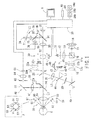
- Fig. 1 is a schematic view showing an optical system and a control system of a fundus camera according to a first preferred embodiment of the present invention.
- the optical system comprises an illumination optical system 10, a fundus observation/photographing optical system 30, a focus target projection optical system 40, an alignment target projection optical system 50, an anterior-segment observation optical system 60, and a fixation target presenting optical system 70.
- the illumination optical system 10 comprises an observation illumination optical system and a photographing illumination optical system.
- the photographing illumination optical system comprises a photographing light source 14 such as a flash lamp, a condenser lens 15, a first shielding plate 17a having a circular shielding portion (e.g., a ring slit), a ring slit 17b having a circular shielding portion at the center and a ring-shaped opening, a second shielding plate 17c having a circular shielding portion (e.g., a ring slit), a relay lens 18, a total reflection mirror 19, a black dot plate 20 having a black dot at the center, a relay lens 21, an apertured mirror 22, and an objective lens 25.
- a photographing light source 14 such as a flash lamp
- a condenser lens 15 such as a flash lamp
- a first shielding plate 17a having a circular shielding portion (e.g., a ring slit)
- a ring slit 17b
- the observation illumination optical system comprises a light source 11 such as a halogen lamp, an infrared transmission filter 12 which transmits near infrared light having a wavelength of 750 nm or more, a condenser lens 13, a dichroic mirror 16 placed between the condenser lens 13 and the ring slit 17b, and the first shielding plate 17a through the objective lens 25.
- the dichroic mirror 16 has properties of reflecting light from the light source 11 and transmitting light from the photographing light source 14.
- the ring slit 17b is placed at a position conjugate with a pupil (an iris) of the eye E
- the first shielding plate 17a is placed at a position conjugate with a cornea of the eye E
- the second shielding plate 17c is placed at a position conjugate with a posterior surface of a crystalline lens of the eye E.
- the first shielding plate 17a, the ring slit 17b, and the second shielding plate 17c in the illumination optical system 10 constitute a shielding member 17.
- the shielding member 17 functions as flare removing means for preventing corneal reflection light and crystalline lens reflection light formed by fundus photographing light from being included in fundus reflection light and photo-received on a two-dimensional image pickup element 35 for photographing to be described later.
- the fundus observation/photographing optical system 30 for photographing an image of a fundus of the eye E comprises a fundus observation optical system and a photographing optical system.
- the fundus observation/ photographing optical system 30 comprises the objective lens 25, a photographing diaphragm 31 placed in the vicinity of an aperture of the apertured mirror 22, a focusing lens 32 movable in the direction of a photographing optical axis L1, an image forming lens 33, and a pop-up mirror 34 which is insertable into and removable from an optical path by means of an inserting/ removing mechanism 39.
- the photographing optical system and the fundus observation optical system share the objective lens 25, and the photographing diaphragm 31 through the image forming lens 33.
- the photographing diaphragm 31 is placed at a position substantially conjugate with the pupil with reference to the objective lens 25.
- the focusing lens 32 is moved in the direction of the optical axis L1 by means of a moving mechanism 49 having a motor.
- the image pickup element 35 has sensitivity to a visible wavelength range.
- a polarization beam splitter 37 reflecting p-polarized light and transmitting s-polarized light, a relay lens 36, and a two-dimensional image pickup element 38 for observation having sensitivity to an infrared wavelength range are placed.
- diopter correction lenses 32a and 32b are provided between the focusing lens 32 and the photographing diaphragm 31 .
- diopter correction lenses 32a and 32b i.e., a negative power lens 32a and a positive power lens 32b
- the diopter correction lens 32a or 32b is inserted into the optical path manually or automatically.
- a diopter correction amount corresponding to the inserted diopter correction lens is added to the fundus observation/photographing optical system 30.
- a dichroic mirror (a wavelength selecting mirror) 24 which functions as an optical path dividing member is placed obliquely on an optical path between the objective lens 25 and the apertured mirror 22 and is insert able into and removable from the optical path.
- the dichroic mirror 24 has properties of reflecting light within an infrared wavelength range of approximately 900 nm or more including light from the alignment target projection optical system 50 and light from an anterior-segment illumination light source 58, and transmitting light within an infrared wavelength range of approximately 900 nm or less including light from the light source 11.
- the dichroic mirror 24 is flipped up by an inserting/removing mechanism 66 and removed from the optical path.
- a known mechanism such as a solenoid and a cam may be used for the inserting/removing mechanism 66.
- Light emitted from the light source 11 is made into infrared light by the infrared filter 12, passes through the condenser lens 13, and is reflected by the dichroic mirror 16 so as to illuminate the first shielding plate 17a.
- the light transmitted through the first shielding plate 17a passes through the ring slit 17b, the second shielding plate 17c, the relay lens 18, the mirror 19, the black point plate 20, and the relay lens 21 to reach the apertured mirror 22.
- the light reflected from the apertured mirror 22 is transmitted through the dichroic mirror 24, is made to converge once in the vicinity of the pupil by the objective lens 25, and then diffuses to illuminate the fundus.
- the light reflected from the fundus passes through the objective lens 25, the dichroic mirror 24, the aperture of the apertured mirror 22, the photographing diaphragm 31, the focusing lens 32, the image forming lens 33, the pop-up mirror 34, the polarization beam splitter 37, and the relay lens 36 to form an observation image of the fundus on the image pickup element 38.
- Output of the image pickup element 38 is inputted to a control unit 80, and the fundus observation image picked up by the image pickup element 38 is displayed on a monitor 8.
- Visible light emitted from the photographing light source 14 passes through the condenser lens 15 and the dichroic mirror 16, and goes along the same optical path as the illumination light for fundus observation, so that the fundus is illuminated by the visible light.
- the light reflected from the fundus passes through the objective lens 25, the aperture of the apertured mirror 22, the photographing diaphragm 31, the focusing lens 32, and the image forming lens 33 to form a photographing image of the fundus on the image pickup element 35.
- the focus target projection optical system 40 comprises an infrared light source 41, a slit target plate 42, two deflection-angle prisms 43 attached to the slit target plate 42, and a polarization beam splitter 44.
- the projection optical system 40 shares an optical path from the polarization beam splitter 44 through the objective lens 25 with the illumination optical system 10.
- the polarization beam splitter 44 is placed in an optical path of the illumination optical system 10 and is used as an optical coupler (a beam combiner) arranged to couple the optical path of the illumination optical system 10 and an optical path of the projection optical system 40.
- the deflection-angle prisms 43 which are arranged to make light deflected in vertically-corresponding directions are aligned laterally interposing a projection optical axis L3 and coincide with a slit which is laterally provided in the target plate 42.
- the projection optical system 40 comprises a first polarizing member arranged to make focus target light have a predetermined polarization direction.
- the observation optical system 30 comprises a second polarizing member arranged to limit, for the image pickup element 38, the focus target light having the predetermined polarization direction of the first polarizing member.
- the projection optical system 40 and the observation optical system 30 comprise linearly polarizing plates having polarizing directions intersecting at right angles, or polarization beam splitters having properties of transmitting or reflecting one light in order to making the light head for the eye E and reflecting or transmitting the other light in order to make the light photo-received on the image pickup element 38, the light having polarizing directions intersecting at right angles. Accordingly, the focus target light reflected by the objective lens 25 is prevented from heading for the image pickup element 38.
- the polarization beam splitter 44 is placed between the light sources of the illumination optical system 10 (i.e., the light source 11 and the light source 14) and the apertured mirror 22 (including a case when the polarization beam splitter 44 is insertable and removable).
- a polarization beam splitter transmitting p-polarized light and reflectings-polarized light is preferably used.
- the optical axis L3 of the projection optical system 40 may be placed at a position deviated in a vertical direction with respect to an optical axis L2 of the illumination optical system 10 in order to prevent focus targets on the fundus from coinciding with a shadow of the black dot plate 20.
- the projection light emitted from the light source 41 passes through the slit of the target plate 42, is subjected to angle deflection into the respective directions by the deflection-angle prisms 43, and is reflected by the polarization beam splitter 44.
- the polarization beam splitter 44 In the light emitted from the light source 41 (natural light), s-polarized light is reflected by the polarization beam splitter 44.
- the light reflected by the polarization beam splitter 44 (the s-polarized light) passes through the relay lens 21, the apertured mirror 22, the dichroic mirror 24, and the objective lens 25, and is projected onto the fundus.
- the focus light projected onto the fundus is made into p-polarized light and s-polarized light by being subjected to diffuse deflection by the fundus.
- the light reflected from the fundus passes through the objective lens 25 and the aperture of the apertured mirror 22 through the pop-up mirror 34 to enter the polarization beam splitter 37.
- the p-polarized light is reflected by the polarization beam splitter 37 and thes-polarized light is transmitted by the polarization beam splitter 37.
- An image of the fundus reflection light reflected by the polarization beam splitter 37 (the p-polarized light) is picked up by the image pickup element 38 via the relay lens 36.
- the projection optical system 40 is used as a target projection optical system which has a projection light source and projects focus targets onto the fundus.
- the observation optical system 30 comprising the image pickup element 38 is used as a photo-receiving optical system comprising a photodetector for photo-receiving the fundus reflection light from the projection optical system 40. Accordingly, the projection optical system 40 and the observation optical system 30 constitute a focus detection optical system.
- Figs. 2A and 2B are views showing the monitor 8 on which images outputted from the image pickup element 38 are displayed.
- Figs. 2A and 2B when split targets (focus targets) are projected onto the fundus, focus target images S1 and S2 are formed.
- the focus target images S1 and S2 are separate in a given direction on the fundus in accordance with a focusing state of the apparatus with respect to the fundus.
- the focus target images S1 and S2 are picked up by the image pickup element 38 together with the fundus image.
- the control unit 80 electrically detects the focusing state of the apparatus with respect to the fundus based on the separation state between the focus target images S1 and S2 and automatically moves the focusing lens 32 based on a result of the detection (automatic focusing control).
- the focus target light is subjected to substantial specular reflection when passing through lens surfaces of the objective lens 25, the cornea, and the crystalline lens, and accordingly reaches the polarization beam splitter 37 in the state of the s-polarized light.
- the polarization beam splitter 37 in the state of the s-polarized light.
- a part of the projection optical system 40 including the light source 41 (i.e., the light source 41, the slit target plate 42, and the deflection-angle prisms 43) is moved in the optical axis direction in conjunction with the movement of the focusing lens 32.
- the part of the projection optical system 40 including the light source 41 is moved so that the fundus of the emmetropic eye and the slit of the slit target plate 42 are substantially conjugate.
- the focusing lens 32 When the focusing lens 32 is located in a position such that an eye with given sphere power (e.g., -3 D) is in focus, the part of the projection optical system 40 including the light source 41 is moved so that the fundus of the eye and the slit of the target plate 42 are substantially conjugate.
- sphere power e.g., -3 D
- a moving mechanism 46 comprises a motor and moves the part of the projection optical system 40 including the light source 41 in the optical axis direction with respect to the polarization beam splitter 44.
- a movable range of the part of the projection optical system 40 covers a movable range corresponding to a diopter correction amount which is obtained only by the movement of the focusing lens 32 and a movable range corresponding to a diopter correction amount which is obtained by the insertion of the diopter correction lens 32a or 32b.
- the moving mechanism 46 has a movable range including a diopter correction range which is obtained by the movement of the focusing lens 32 with the diopter correction lens being inserted.
- the movable range of the part of the projection optical system 40 is changed in accordance with the insertion/removal state of the diopter correction lenses 32a and 32b in the photographing optical path.
- the movable range is set in accordance with the insertion/removal state of the diopter correction lenses 32a and 32b, the part of the projection optical system 40 is moved within the movable range in conjunction with the movement of the focusing lens 32 (detailed descriptions are provided later).
- the alignment target projection optical system 50 for projecting alignment target light is configured such that a plurality of infrared light sources are concentrically arranged at intervals of 45 degrees having the optical axis L1 at the center.
- the alignment target projection optical system 50 comprises first target projection optical systems having infrared light sources 51 and collimating lenses 52 and arranged laterally symmetrical with respect to the optical axis L1 (0 degree and 180 degrees), and second target projection optical systems having six infrared light sources 53 and arranged at positions different from those of the first target projection optical systems.
- the first projection optical systems project infinite targets onto the cornea from right and left directions
- the second projection optical systems project finite targets onto the cornea from up and down directions or oblique directions.
- the first target projection optical systems (0 degree and 180 degrees) and a part of the second target projection optical systems (45 degrees and 135 degrees) are shown for the sake of illustration.
- the anterior-segment observation (photographing) optical system 60 for picking up an observation image of an anterior-segment of the eye E comprises a field lens 61, a total reflection mirror 62, a diaphragm 63, a relay lens 64, and a two-dimensional image pickup element (photodetector) 65 having sensitivity to the infrared wavelength range, which are arranged in a reflecting direction of the dichroic mirror 24.
- the image pickup element 65 doubles as image pickup means for alignment target detection, and picks up the image of the anterior-segment illuminated by the illumination light source 58 and an image of an alignment target.
- Illumination light emitted from the illumination light source 58 is reflected by the anterior-segment, and the light reflected from the anterior-segment passes through the objective lens 25, the dichroic mirror 24, and the field lens 61 through the relay lens 64, and is photo-received on the image pickup element 65.
- Alignment target light emitted from the light sources of the alignment target projection optical system 50 is projected onto the cornea, and the light reflected from the cornea is photo-received on (projected onto) the image pickup element 65 via the objective lens 25 through the relay lens 64.
- Output of the image pickup element 65 is inputted to the control unit 80, and the anterior-segment image picked up by the image pickup element 65 is displayed on the monitor 8.
- the anterior-segment observation optical system 60 doubles as means for detecting an alignment state of the apparatus main body with respect to the eye E.
- the fixation target presenting optical system 70 for presenting a fixation target for fixation of the eye E comprises a red light source (a fixation lamp) 74, a shielding plate 71 with an opening, and a relay lens 75.
- the fixation target presenting optical system 70 shares an optical path from the pop-up mirror 34 through the objective lens 25 with the fundus observation/ photographing optical system 30 via the polarization beam splitter 37.
- the fixation target is formed by illuminating the shielding plate 71 from behind by the light source 74. Illumination light emitted from the light source 74 passes through the opening of the shielding plate 71, the relay lens 75, the polarization beam splitter 37, the pop-up mirror 34, the image forming lens 33, the focusing lens 32, the apertured mirror 22, the dichroic mirror 24, and the objective lens 25, and converges at the fundus, so that the examinee visually perceives the light from the opening of the shielding plate 71 as the fixation target.
- the image pickup elements 65, 38 and 35 are connected to the control unit 80.
- the control unit 80 detects the alignment target in the anterior-segment image picked up by the image pickup element 65.
- the control unit 80 detects and processes the focus target images in the fundus image picked up by the image pickup element 38.
- the control unit 80 detects corneal astigmatism of the eye E based on the alignment target image picked up by the image pickup element 65.
- the control unit 80 is connected with the monitor 8 and controls the image displayed on the monitor 8.
- the control unit 80 is connected with the moving mechanism 49, the moving mechanism 46, the inserting/removing mechanism 39, a switch unit 84 having various switches, a memory 85 as storage means, the light sources, and other constituent elements.
- the switch unit 84 preferably comprises a focus adjustment switch 84a, a photographing starting switch 84b, a changeover switch 84c for inserting and removing the diopter correction lenses 32a and 32b.
- the examiner makes the face of the examinee supported by a face support unit (not shown). Then, the examiner performs alignment of the apparatus with respect to the eye E by performing tilting operation of a joystick (not shown) in order to laterally and horizontally move the apparatus main body incorporating the optical systems described above. In this occasion, the alignment can be smoothly performed by outputting the anterior-segment image picked up by the anterior-segment observation optical system 60 to the monitor 8.
- the fundus image picked up by the image pickup element 38 is displayed on the monitor 8. While observing the fundus image, the examiner finely adjusts the alignment state by manually operating the joystick in order to allow photographing to be performed in a desired state.
- the focus target images S1 and S2 from the projection optical system 40 are displayed in the center as shown in Fig. 2A , and accordingly the focusing lens 32 is moved in the optical axis direction based on the focus images S1 and S2 in order to perform focusing on the fundus.
- the control unit 80 moves the part of the projection optical system 40 in the optical axis direction in conjunction with the movement of the focusing lens 32 within the movable range corresponding to the diopter correction range which is obtained only by the movement of the focusing lens 32 (see Fig. 3A ).
- the focusing is performed either manually by the examiner using the focus adjustment switch 84a or automatically by the control unit 80.
- the control unit 80 controls driving of the moving mechanism 49 so that the focus target images S1 and S2 coincide.
- photographing is performed based on a trigger signal for starting photographing which is outputted either automatically or manually.
- the control unit 80 drives the inserting/ removing mechanism 39 to remove the pop-up mirror 34 from the optical path, drives the inserting/removing mechanism 66 to remove the dichroic mirror 24 from the optical path, and controls the photographing light source 14 to emit light.
- the photographing image is picked up by the image pickup element 35, and image data is stored in the memory 85.
- the control unit 80 controls the monitor 8 to change the image displayed thereon to the fundus photographing image in color picked up by the image pickup element. 35.
- the examiner presses the changeover switch 84c to insert the diopter correction lens 32a or 32b into the photographing optical path in order to perform focusing.
- the diopter correction lens 32a or 32b may be automatically inserted. For example, if focusing is not achieved even though the focusing lens 32 is moved to a movement limit position, the diopter correction lens 32a or 32b is automatically inserted.
- the control unit 80 controls the moving mechanism 49 to move the part of the projection optical system 40 to a position corresponding to a diopter correction amount which is obtained by the insertion of the diopter correction lens 32a or 32b and the position to which the focusing lens 32 is moved.
- the position to which the part of the projection optical system 40 including the light source 41 is moved is corrected in accordance with the insertion/removal state of the diopter correction lenses 32a and 32b.
- the control unit 80 detects the insertion states of the individual diopter correction lenses 32a and 32b into the photographing optical path based on a signal from a sensor which may be placed in the vicinity of the diopter correction lenses 32a and 32b (e.g. a photo sensor), a changeover signal outputted from the changeover switch 84c, a driving signal from the driving unit 32c, or other signals.
- Figs. 3A to 3C are views showing examples of the movable range of the part of the projection optical system 40 in the state of the diopter correction lenses 32a and 32b being removed, in the state of the diopter correction lens 32a being inserted, and it the state of the diopter correction lens 32b being inserted.
- the movable range is set corresponding to a given diopter correction range which is obtained by the movement of the focusing lens 32 with the diopter correction lenses 32a and 32b being removed (a range from -12 D to +12 D with 0 D in between).
- the movable range is set corresponding to a given diopter correction range which is obtained by the movement of the focusing lens 32 with the diopter correction lens 32a being inserted (a range from -30 D to -6 D with -18 D in between).
- the control unit 80 sets a moving direction (a minus direction) and a moving distance of the part of the projection optical system 40 corresponding to the diopter correction amount of the diopter correction lens 32a (e.g. -18 D). For example, the control unit 80 moves the part of the projection optical system 40 to a position (-30 D) which is the sum of the position to which the part of the projection optical system 40 is moved before the diopter correction lens 32a is inserted (-12 D) and the diopter correction amount of the diopter correction lens 32a (-18 D).
- control unit 80 may control the driving of the moving mechanism 49 to move the focusing lens 32 to a position corresponding to the diopter correction amount before the diopter correction lens 32a is inserted.
- focus adjustment from the diopter correction amount in the state of the diopter correction lens 32a being removed can be performed after the diopter correction lens 32a is inserted.
- the movable range is set corresponding to a given diopter correction range which is obtained by the movement of the focusing lens 32 with the diopter correction lens 32b being inserted (a range from +6 D to +30 D with +18 D in between).
- Operations of the control unit 80 may be the same as the operations when the diopter correction lens 32a is being inserted, and detailed descriptions are omitted.
- control unit 80 controls the driving of the moving mechanism 49 to perform focusing on the fundus based on the separation information of the focus target images S1 and S2 in order that the focus target images S1 and S2 coincide.
- the examiner may manually perform focusing on the fundus in order that the focus target images S1 and S2 coincide.
- the control unit 80 moves the part of the projection optical system 40 in the optical axis direction in conjunction with the movement of the focusing lens 32 within the movable range corresponding to the diopter correction range which is obtained by the insertion of the diopter correction lens and the movement of the focusing lens 32.
- the control unit 80 moves the part of the projection optical system 40 within the movable range corresponding to the diopter correction lens 32a.
- the control unit 80 moves the part of the projection optical system 40 by the diopter correction amount which is obtained by the movement of the focusing lens 32.
- the focus target images on the fundus can be picked up by the image pickup element 38 even if the eye E has severe ametropia and the diopter correction lens is being inserted into the photographing optical path of the photographing optical system 30.
- proper automatic focusing control becomes possible.
- Manual focusing by the examiner also becomes possible by the same operation as that in the state of the diopter correction lenses 32a and 32b being removed.
- another correction lens corresponding to the insertion of the diopter correction lens may be provided so as to be insertable into and removable from the optical path of the projection optical system 40.
- a negative power lens corresponding to the diopter correction amount of the diopter correction lens 32a is inserted between the polarization beam splitter 44 and the prisms 43. This operation saves the movement amount of the part of the projection optical system 40.
- the movable range of the part of the projection optical system 40 in the state of the diopter correction lens 32a being inserted and the movable range of the part of the projection optical system 40 in the state of the diopter correction lens 32a being removed can be made substantially equal.
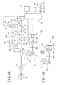
- Figs. 4A and 4B which are assigned the same reference numerals as the constituent elements in Fig. 1 , have the same configurations and functions as the constituent elements in Fig. 1 unless descriptions are particularly provided.
- Figs. 4A and 4B which are assigned the same reference numerals as the constituent elements in Fig. 1 , have the same configurations and functions as the constituent elements in Fig. 1 unless descriptions are particularly provided.
- a target projection optical system 140 for projecting spot light onto the fundus via a center of the pupil and a photo-receiving optical system 160 for picking up the light reflected from the fundus via the anterior-segment as a given pattern image (e.g., a ring pattern image, a plurality of spot images) and making the image photo-received on a two-dimensional photodetector.
- a given pattern image e.g., a ring pattern image, a plurality of spot images
- the projection optical system 140 comprises an infrared point light source 141 such as an LED and an SLD, a projection lens 142, and a beam splitter 144 which functions as an optical path dividing member for dividing the focus light and the fundus observation light (e.g., a dichroic mirror which performs wavelength separation on the focus light and the fundus observation light), which are placed on an optical axis L3.
- the projection optical system 140 shares the optical path from the beam splitter 144 through the objective lens 25 with the fundus observation optical system 30.
- Adichroicmirror 137 has proper ties of reflecting visible light and transmitting infrared light.
- the photo-receiving optical system 160 comprises a beam splitter 169, a pinhole plate 161 with an opening which is placed at a position substantially conjugate with the fundus, a collimator lens 163, a ring lens 165, and a two-dimensional photodetector 167 which is placed at a position substantially conjugate with the fundus, which are placed in a reflecting direction of the beam splitter 169.
- the photo-receiving optical system 160 shares the optical path from the objective lens 25 through the beam splitter 169 with the illumination optical system 10.
- a part of the photo-receiving optical system 160 including the two-dimensional photodetector 167 (e.g., the pinhole plate 161 through the two-dimensional photodetector 167) is movable in the direction of an optical axis in conjunction with the movement of the focusing lens 32 by the driving of the moving mechanism 46.
- the part of the photo-receiving optical system 160 including the two-dimensional photodetector 167 is moved so that the fundus of the emmetropic eye and the opening of the pinhole plate 161 are substantially conjugate.
- the part of the photo-receiving optical system 160 including the two-dimensional photodetector 167 is moved so that the fundus and the opening of the pinhole plate 161 are substantially conjugate.
- a position to which the part of the photo-receiving optical system 160 including the two-dimensional photodetector 167 is moved in conjunction with the movement of the focusing lens 32 is corrected in accordance with the insertion/removal state of the diopter correction lenses 32a and 32b as in the case of moving the part of the projection optical system 40 including the light source 41 according to the first preferred embodiment of the present invention in Fig. 1 .
- the ring lens 165 comprises a lens portion and a ring target plate having a ring opening, and is placed at a position substantially conjugate with the pupil.
- the two-dimensional photodetector 167 is placed at a focal point of the ring portion, and becomes conjugate with the fundus when focusing is achieved between the fundus and the image pickup element 38 (the image pickup element 35).
- the ring target plate is placed between the focusing lens 32 and the two-dimensional photodetector 167 in a position substantially conjugate with the anterior-segment (e.g., a position substantially conjugate with the pupil, a position substantially conjugate with the fundus).
- Light emitted from the light source 141 passes through the lens 142 through the objective lens 25 via the pop-up mirror 34 to be projected onto the fundus, so that a spot-shaped point light source image is projected onto the fundus.
- the point light source image is reflected and scattered by the fundus to exit from the eye E, passes through the objective lens 25, is reflected by a reflection plane of the apertured mirror 22, passes through the relay lens 21, the beam splitter 169, the opening of the pinhole plate 161, the collimator lens 163, is converged by the ring lens 165, and is photo-received on the two-dimensional photodetector 167 as a ring image.
- a photo-receiving signal from the two-dimensional photodetector 167 is inputted to the control unit 80.
- a thin ring image with less blur having the same size as the ring opening of the ring lens 165 is photo-received on the two-dimensional photodetector 167.
- a thick ring image with blur having a size different from the ring image which is obtained when the fundus is in focus is photo-received on the two-dimensional photodetector 167.
- the eye has spherical ametropia
- the ring image has a size in proportion to the degree of the spherical ametropia.
- the ring image photo-received on the two-dimensional photodetector 167 has an oval shape in accordance with the astigmatic ametropia.
- control unit 80 detects the focusing state of the apparatus with respect to the fundus by analyzing the ring image photo-received on the two-dimensional photodetector 167.
- the control unit 80 performs focusing on the fundus by controlling the driving of the moving mechanism 46 and the driving of the moving mechanism 49 based on the detected focusing state of the apparatus with respect to the fundus.
- the control unit 80 moves the focusing lens 32 in the optical axis direction by means of the moving mechanism 49 and moves the part of the photo-receiving optical system 160 by means of the moving mechanism 46.
- the two-dimensional photodetector 167 is brought into a position conjugate with the fundus such that the ring image on the two-dimensional photodetector 167 is made thinnest or brightest.
- focus adjustment between the image pickup element 35 (or the image pickup element 38) and the fundus is performed.
- polarization beam splitters having properties of reflecting one light and transmitting the other light, the light having polarizing directions intersecting at right angles, which is used in the first preferred embodiment of the present invention may be used instead of the beam splitter 144 and the beam splitter 169.
- a diaphragm 170 with two holes which functions as a pattern target plate in which the two holes are placed at positions whose distances from a photo-receiving optical axis are equal, and an image forming lens 171 functioning as a light collect ing member which collects light having passed through the diaphragm 170 on the two-dimensional photodetector 167 may be used as shown in Fig. 4B .
- two spot images coincide so that one spot image on the photo-receiving optical axis is photo-received on the two-dimensional photodetector 167.
- two spot images are photo-received on the two-dimensional photodetector 167.
- the focus detection optical system is configured such that the focusing state of the apparatus with respect to the fundus is detected by the ring image photo-received on the two-dimensional photodetector 167 (see Fig. 4A ), the cause of blur in the image can be judged.
- the ring image photo-received on the two-dimensional photodetector 167 in the case of the eye with astigmatism has an oval shape with a long diameter and a short diameter. The long diameter and the short diameter of the ring image change depending on astigmatic power of the eye.
- the control unit 80 detects the focusing state of the apparatus with respect to the fundus based on the ring image photo-received on the two-dimensional photodetector 167. Then, the control unit 80 controls the driving of the moving mechanism 49 in order that the focusing lens 32 may be located in a position corresponding to spherical equivalent power of the eye based on the detected focusing state of the apparatus with respect to the fundus. In addition, the control unit 80 moves the part of the photo-receiving optical system 160 in conjunction with the movement of the focusing lens 32 (subsequent operation are performed as described above). In the second preferred embodiment of the present invention, the position corresponding to the spherical equivalent power of the eye is set as a focusing completion position.
- the control unit 80 controls the monitor 8 to display the ring target image, which is photo-received on the two-dimensionalphotodetector 167 when the focusing lens 32 is located in the focusing completion position, and the fundus observation image while superimposing the images one another.
- the control unit 80 may detect information on the position of the obtained ring image and control the monitor 8 to display electronic graphics according to the detected information.
- the control unit 80 may control the monitor 8 to fixedly display a ring mark based on the ring image which is obtained when the focusing lens 32 is located in the focusing completion position.
- control unit 80 controls the monitor 8 to display the ring image, which is obtained at the time when focusing is completed, in association with the obtained fundus image in color.
- the control unit 80 With the focusing lens 32 being located in the position corresponding to the SE value, the control unit 80 detects the focusing state of the apparatus with respect to the fundus with reference to the position to which the focusing lens 32 being located in the position corresponding to the SE value is moved, and controls the monitor 8 to electronically display a focus deviation amount and a focus deviation direction of the apparatus with respect to the fundus (see Figs. 5A and 5B ). In this case, the control unit 80 detects a movement amount of the focusing lens 32 from the position corresponding to the SE value and controls the monitor 8 to electronically display the focus deviation amount and the focus deviation direction.
- FIG. 5A an indicator is moved in the positive direction or the negative direction with reference to the SE value in accordance with the movement amount of the focusing lens 32 from the position corresponding to the SE value.
- Fig. 5B the position of the focusing lens 32 is converted into refractive power or the eye, and the SE value is indicated by a gauge presenting eye refractive power values in order to display the movement amount of the focusing lens 32 from the position corresponding to the SE value.
- the control unit 80 may set a focus position corresponding to refractive power in a steepest meridian direction of astigmatism of the eye as a first focusing limit position, set a focus position corresponding to refractive power in a flattest meridian direction of astigmatism of the eye as a second focusing limit position, and control the monitor 8 to display limit marks corresponding to the first and second focusing limit positions (see Figs. 5A and 5B ).
- graphic marks A1 correspond to the first focusing limit position
- graphic marks A2 correspond to the second focusing limit position.
- Fig. 6 is a schematic view showing an optical system for illustrating the second focusing mode.
- the projection optical system 40 comprises the infrared light source 41, the slit target plate 42, the two deflection-angle prisms 43 attached to the slit target plate 42, the projection lens 47, and a spot mirror 48 which is placed obliquely on the optical path of the illumination optical system 10.
- the spot mirror 48 is fixed to the top end of a lever 45, and is normally placed obliquely on the optical path and is removed from the optical path by rotating a rotary solenoid 46 about the shaft with predetermined timing before the photographing.
- the spot mirror 48 is placed at a position substantially conjugate with the fundus.
- the light source 41, the slit target plate 42, the deflection-angle prisms 43, the projection lens 47, the spot mirror 48, and the lever 45 are moved in conjunction with the focusing lens 32 in the direction of an optical axis by the moving mechanism 49.
- the light having passed through the slit target plate 42 is transmitted through the deflection-angle prisms 43 and the projection lens 47, and is reflected by the spot mirror 48, and thereafter the light passes through the relay lens 21, the apertured mirror 22, the dichroic mirror 24, and the objected lens 25, and is projected onto the fundus.
- Fig. 6 When the fundus is out of focus, target images of the slit target plate 42 are separate, and when the fundus is in focus, the target images coincide. The target images projected onto the fundus are picked up by the image pickup element 38 together with the fundus observation image.
- the other constituent elements in Fig. 6 may have the same configurations as the corresponding constituent elements in Fig. 1 , and descriptions thereof are omitted.
- Fig. 7 is a view showing a control system of the apparatus for illustrating the second focusing mode.
- the switch unit 84 comprises a mode selection switch 84d for switching between a first focusing mode and the second focusing mode.
- the constituent elements assigned the same reference numerals as the constituent elements in Fig. 1 have the same configurations and functions as the constituent elements in Fig. 1 unless descriptions are particularly provided.
- the control unit 80 is connected with an eye determining unit 110 for determining whether the eye is a right eye or a left eye, and the control unit 80 determines whether the eye is a right eye or a left eye based on an output signal from the eye determining unit 110.
- the mode selection switch 84d selective switching can be performed between the first focusing mode in which the position to which the focusing lens 32 is moved under automatic focusing control is set as the focusing completion position and the second focusing mode in which the position to which the focusing lens 32 is moved by the driving of the moving mechanism 49 is set based on measurement data obtained by an eye refractive power measurement apparatus.
- the control unit 80 can control the monitor 8 to display the focusing state of the apparatus with respect to the fundus which is obtained based on a result of the detection by the focus detection optical system as first focusing information (see Figs. 2A and 2B ).
- first focusing information include the split target images which are displayed on the monitor 8 based on the image-pickup signal outputted from the image pickup element 38.
- the control unit 80 moves the focusing lens 32 based on the measurement data obtained by the eye refractive power measurement apparatus.
- the control unit 80 sets the focusing completion position of the focusing lens 32 to the position corresponding to the SE value and controls the monitor 8 to display focusing information based on the set position as a second focusing information which is different from the first focusing information.
- the control unit 80 moves the focusing lens 32 based on the measurement data corresponding to a result of the eye determination by the eye determining unit 110.
- the control unit 80 corrects astigmatism of the eye by controlling the driving of the moving mechanism 19 to automatically move the focusing lens 32 to the position corresponding to the SE value which is calculated based on the sphere power and the astigmatic power of the eye in the measurement data.
- Fig. 7 is a view in which the second focusing information is displayed together with the fundus observation image.
- Figs. 8A and 8B are enlarged views of the second focusing information.
- the control unit 80 detects the focusing state of the apparatus with respect to the fundus with reference to the position of the focusing lens 32 corresponding to the SE value and controls the monitor 8 to display a focus deviation amount and a focus deviation direction of the apparatus with respect to the fundus which are obtained based on a result of the detection as the second focusing information.
- the control unit 80 controls the monitor 8 not to display the first focusing information when the second focusing information is displayed.
- FIG. 8A an indicator is moved in the positive direction or the negative direction with reference to the SE value in accordance with the movement amount of the focusing lens 32 from the position corresponding to the SE value.
- Fig. 8B the position of the focusing lens 32 is converted into refractive power of the eye, and a mark for the SE value is provided in a gauge presenting eye refractive power values in order to display the movement amount of the focusing lens 32 from the position corresponding to the SE value.
- the examiner is allowed to perform focusing on a desired portion while checking the focus deviation amount and the focus deviation direction from the position corresponding to the SE value based on the focus target images which are electronically displayed on the monitor 8 (see Figs. 8A and 8B ).
- Limit marks similar to the limit marks in Figs. 5A and 5B may be displayed.
- Electronic graphics which are displayed as the second focusing information may depict the focus bars (focus target images) which are displayed as the first focusing information.
- the first focusing information may be electronically displayed (see marks E1 and E2 in Fig. 9B).
- Figs. 10A and 10B are views in which a display pattern of the focus bars is changed between the first focusing information and the second focusing information.
- the alignment target projection optical system 50 doubles as a corneal target projection optical system for projecting targets for corneal astigmatism detection onto the cornea.
- the anterior-segment observation optical system 60 doubles as a target detection optical system for detecting the targets projected onto the cornea.
- Fig. 11 is a view showing an observation screen for the anterior-segment image picked up by the image pickup element 65.
- Figs. 12A and 12B are views showing a fundus observation screen.
- the control unit 80 determines whether or not corneal astigmatism is present in the eye based on image forming positions of corneal target images Ma to Mh on the image pickup element 55, and controls the monitor 8 to display a result of the determination together with the fundus photographing image (or the fundus observation image or the anterior-segment image).
- control unit 80 controls the monitor 8 to make a guiding instruction to move the focusing lens 32 to a position corresponding to an average value of corneal refractive power of the eye based on the image forming positions of the target images Ma to Mh on the image pickup element 65.
- Fig. 13 is a graph showing an example of corneal refractive power in meridian directions as a result of the calculation.
- the graph in Fig. 13 show a that corneal refractive power in the flattest meridian (R1) direction is 42.0 D, corneal refractive power in the steepest meridian (R2) direction is 45.0 D, corneal astigmatic power CYL is -3.0 D (taking the negative side), and a corneal astigmatic axial angle A is 90 degrees.
- the control unit 80 determines whether or not corneal astigmatism is present in the eye based on whether an absolute value of the calculated corneal astigmatic power CYL is beyond a predetermined value (e.g., 0.5 D). When it is determined that the corneal astigmatism is present in the eye, the control unit 80 controls the monitor 8 to inform that the eye has astigmatism (see icons Cyl in Figs. 11 , 12A, and 12B ).
- control unit 80 controls the monitor 8 to display a result of the determination (see the icons Cyl in Figs. 12A and 12B ) together with the fundus observation image.
- control unit 80 controls the monitor 8 to make a guiding instruction to move the focusing lens 32 to the position corresponding to the average value of the corneal refractive power.
- control unit 80 calculates the average value of the refractive power in the R1 direction and the refractive power in the R2 direction (average refractive power AVE) based on the calculated refractive power data.
- control unit 80 calculates corneal refractive power FD in the direction of separation between the target image images S1 and S2 (a vertical direction). In the case of the data shown in Fig. 13 , average refractive power AVE of 43.5 D ((42.0 + 45.0)/2) and corneal refractive power FD of 42.0 are obtained.
- the deviation amount H defines the deviation direction and the deviation amount (the deviation degree) between the position corresponding to the average refractive power AVE to which the focusing lens 32 is moved and the position to which the focusing lens 32 is moved when the focus target images S1 and S2 coincide.
- the deviation direction is defined by negative and positive values of the deviation amount H
- the deviation amount is defined by an absolute value of the deviation amount H.
- the monitor 8 may electronically display a reticle mark Lf indicating a direction in which the focus target images S1 and S2 are to be moved (an operating direction of a focus knob) and a moving amount of the focus target images S1 and S2 (an operation amount of the focus knob) based on the deviation amount H calculated as described above.
- the control unit 80 changes a deviation amount ⁇ Lf of the display position of the reticle mark Lf with respect to a reference display position K (the target coinciding position) in accordance with the degree of the absolute value of the deviation amount H.
- the focusing lens 32 is located in the position corresponding to the average corneal refractive power AVE.
- the fundus image picked up by the image pickup element 35 in stored in the memory 85 is stored in the memory 85.
- the control unit 80 controls the monitor 8 to display the result of the determination that the corneal astigmatism is present in the eye (see the icons Cy1 in Figs. 12A and 12B ) together with the fundus photographing image.
- the above configuration allows diopter correction to be performed on a number of astigmatic eyes.
- the determination whether or not corneal astigmatism is present in the eye and the guiding instruction to move the focusing lens based on the detected positions of the target images may be performed without calculating the corneal refractive power. If the target projection optical system is configured to project at least three point light sources onto the cornea Ec, corneal curvature measurement with astigmatism detection can be performed.
- Indicators as shown in Fig. 14 may be displayed when the above electronic display is performed.
- the driving of the moving mechanism 49 may be controlled.
- the control unit 80 detects the deviation of the corneal refractive power FD from the average corneal refractive power AVE (the deviation amount H), and calculates the moving direction and the moving amount of the focusing lens 32 with respect to the coinciding position of the focus target images S1 and S2 based on the deviation direction and the deviation degree.
- the control unit 80 controls the driving of the moving mechanism 49 based on the obtained moving direction and the obtained moving amount.
Landscapes
- Life Sciences & Earth Sciences (AREA)
- Health & Medical Sciences (AREA)
- Medical Informatics (AREA)
- Biophysics (AREA)
- Ophthalmology & Optometry (AREA)
- Engineering & Computer Science (AREA)
- Biomedical Technology (AREA)
- Heart & Thoracic Surgery (AREA)
- Physics & Mathematics (AREA)
- Molecular Biology (AREA)
- Surgery (AREA)
- Animal Behavior & Ethology (AREA)
- General Health & Medical Sciences (AREA)
- Public Health (AREA)
- Veterinary Medicine (AREA)
- Eye Examination Apparatus (AREA)
Applications Claiming Priority (3)
| Application Number | Priority Date | Filing Date | Title |
|---|---|---|---|
| JP2008092397A JP5101370B2 (ja) | 2008-03-31 | 2008-03-31 | 眼底撮影装置 |
| JP2008255757A JP5199009B2 (ja) | 2008-09-30 | 2008-09-30 | 眼底カメラ |
| JP2009040245A JP5435698B2 (ja) | 2009-02-24 | 2009-02-24 | 眼底カメラ |
Publications (2)
| Publication Number | Publication Date |
|---|---|
| EP2106741A1 true EP2106741A1 (fr) | 2009-10-07 |
| EP2106741B1 EP2106741B1 (fr) | 2011-11-02 |
Family
ID=40821600
Family Applications (1)
| Application Number | Title | Priority Date | Filing Date |
|---|---|---|---|
| EP09156961A Ceased EP2106741B1 (fr) | 2008-03-31 | 2009-03-31 | Caméra pour fond |
Country Status (2)
| Country | Link |
|---|---|
| US (1) | US7837329B2 (fr) |
| EP (1) | EP2106741B1 (fr) |
Cited By (6)
| Publication number | Priority date | Publication date | Assignee | Title |
|---|---|---|---|---|
| ITTV20100025A1 (it) * | 2010-02-25 | 2011-08-26 | Ct Vue S P A | Apparato d'ispezione del fondo oculare e procedimento relativo |
| WO2012119633A1 (fr) * | 2011-03-04 | 2012-09-13 | Eyesight & Vision Gmbh | Ensemble projecteur et appareil médical équipé de cet ensemble projecteur |
| EP2730214A1 (fr) * | 2012-11-09 | 2014-05-14 | Canon Kabushiki Kaisha | Appareil ophtalmologique, procédé de commande et programme |
| EP2827759A4 (fr) * | 2012-03-21 | 2015-12-02 | Optovue Inc | Rétinographe |
| WO2016037980A1 (fr) * | 2014-09-12 | 2016-03-17 | Centervue S.P.A. | Appareil d'examen de l'œil |
| EP3721788A4 (fr) * | 2017-12-04 | 2021-08-18 | Nidek Co., Ltd. | Dispositif de mesure de puissance réfractive oculaire |
Families Citing this family (18)
| Publication number | Priority date | Publication date | Assignee | Title |
|---|---|---|---|---|
| JP5427494B2 (ja) * | 2009-07-03 | 2014-02-26 | 株式会社ニデック | 眼底撮影装置 |
| JP5355305B2 (ja) * | 2009-08-31 | 2013-11-27 | キヤノン株式会社 | 眼科撮影装置 |
| JP5641786B2 (ja) * | 2010-05-28 | 2014-12-17 | キヤノン株式会社 | 眼科装置、制御方法及びプログラム |
| JP5600478B2 (ja) | 2010-06-01 | 2014-10-01 | キヤノン株式会社 | 眼科撮影装置及びその制御方法 |
| JP5550494B2 (ja) | 2010-08-31 | 2014-07-16 | キヤノン株式会社 | 眼科撮影装置、その制御方法およびプログラム |
| JP5729949B2 (ja) * | 2010-08-31 | 2015-06-03 | キヤノン株式会社 | 撮像装置、その制御方法及びプログラム |
| US9398851B2 (en) | 2011-06-24 | 2016-07-26 | Remidio Innovative Solutions Pvt. Ltd. | Retinal imaging device |
| TWI450705B (zh) * | 2011-10-28 | 2014-09-01 | Crystalvue Medical Corp | Three - axis positioning device and method for ophthalmic detection instrument |
| US9655507B2 (en) * | 2011-11-02 | 2017-05-23 | Nidek Co., Ltd. | Corneal imaging device |
| JP6045895B2 (ja) | 2012-10-01 | 2016-12-14 | 株式会社トプコン | 眼科観察装置 |
| JP6471466B2 (ja) * | 2014-11-12 | 2019-02-20 | 株式会社ニデック | 眼科装置、及びそれに用いる処理プログラム |
| JP6518132B2 (ja) | 2015-05-26 | 2019-05-22 | 株式会社トプコン | 眼科撮影装置 |
| CN106963335B (zh) * | 2015-11-13 | 2022-01-04 | 尼德克株式会社 | 主观式检眼装置 |
| JP6159446B2 (ja) * | 2016-05-30 | 2017-07-05 | 株式会社トプコン | 眼底撮影装置 |
| WO2019175903A1 (fr) * | 2018-03-16 | 2019-09-19 | Remidio Innovative Solutions Pvt. Ltd. | Dispositif d'imagerie ophtalmique pour imager des régions d'œil postérieure et antérieure |
| US12383132B2 (en) * | 2018-11-16 | 2025-08-12 | Arizona Board Of Regents On Behalf Of The University Of Arizona | Identification and control of myopic progression using distortion |
| CN116490117A (zh) * | 2020-10-27 | 2023-07-25 | 株式会社拓普康 | 眼科观察装置 |
| CN113440099B (zh) * | 2021-06-07 | 2023-08-15 | 天津市索维电子技术有限公司 | 一种人眼视光综合检查装置和方法 |
Citations (3)
| Publication number | Priority date | Publication date | Assignee | Title |
|---|---|---|---|---|
| EP1752084A2 (fr) * | 2005-08-05 | 2007-02-14 | Kabushiki Kaisha TOPCON | Caméra de fond d'oeil |
| JP2007151651A (ja) * | 2005-12-01 | 2007-06-21 | Topcon Corp | 眼底カメラ |
| JP2007202724A (ja) | 2006-01-31 | 2007-08-16 | Nidek Co Ltd | 眼底カメラ |
Family Cites Families (1)
| Publication number | Priority date | Publication date | Assignee | Title |
|---|---|---|---|---|
| JP4047255B2 (ja) * | 2003-09-25 | 2008-02-13 | 株式会社ニデック | 眼底カメラ |
-
2009
- 2009-03-31 US US12/415,547 patent/US7837329B2/en not_active Expired - Fee Related
- 2009-03-31 EP EP09156961A patent/EP2106741B1/fr not_active Ceased
Patent Citations (3)
| Publication number | Priority date | Publication date | Assignee | Title |
|---|---|---|---|---|
| EP1752084A2 (fr) * | 2005-08-05 | 2007-02-14 | Kabushiki Kaisha TOPCON | Caméra de fond d'oeil |
| JP2007151651A (ja) * | 2005-12-01 | 2007-06-21 | Topcon Corp | 眼底カメラ |
| JP2007202724A (ja) | 2006-01-31 | 2007-08-16 | Nidek Co Ltd | 眼底カメラ |
Cited By (12)
| Publication number | Priority date | Publication date | Assignee | Title |
|---|---|---|---|---|
| ITTV20100025A1 (it) * | 2010-02-25 | 2011-08-26 | Ct Vue S P A | Apparato d'ispezione del fondo oculare e procedimento relativo |
| WO2011104062A3 (fr) * | 2010-02-25 | 2013-01-10 | Centervue S.P.A. | Appareil photo pour fond d'œil |
| US9078602B2 (en) | 2010-02-25 | 2015-07-14 | Centervue S.P.A. | Fundus camera |
| WO2012119633A1 (fr) * | 2011-03-04 | 2012-09-13 | Eyesight & Vision Gmbh | Ensemble projecteur et appareil médical équipé de cet ensemble projecteur |
| EP2827759A4 (fr) * | 2012-03-21 | 2015-12-02 | Optovue Inc | Rétinographe |
| EP2730214A1 (fr) * | 2012-11-09 | 2014-05-14 | Canon Kabushiki Kaisha | Appareil ophtalmologique, procédé de commande et programme |
| CN103799974A (zh) * | 2012-11-09 | 2014-05-21 | 佳能株式会社 | 眼科装置及控制方法 |
| US9314158B2 (en) | 2012-11-09 | 2016-04-19 | Canon Kabushiki Kaisha | Ophthalmologic apparatus, control method |
| CN103799974B (zh) * | 2012-11-09 | 2016-06-15 | 佳能株式会社 | 眼科装置及控制方法 |
| WO2016037980A1 (fr) * | 2014-09-12 | 2016-03-17 | Centervue S.P.A. | Appareil d'examen de l'œil |
| US10070785B2 (en) | 2014-09-12 | 2018-09-11 | Centervue S.P.A. | Eye examination apparatus |
| EP3721788A4 (fr) * | 2017-12-04 | 2021-08-18 | Nidek Co., Ltd. | Dispositif de mesure de puissance réfractive oculaire |
Also Published As
| Publication number | Publication date |
|---|---|
| US7837329B2 (en) | 2010-11-23 |
| US20090244483A1 (en) | 2009-10-01 |
| EP2106741B1 (fr) | 2011-11-02 |
Similar Documents
| Publication | Publication Date | Title |
|---|---|---|
| EP2106741B1 (fr) | Caméra pour fond | |
| JP5772117B2 (ja) | 眼底撮影装置 | |
| EP1452128B1 (fr) | Appareil pour la photographie du fond de l'oeil | |
| JP4359489B2 (ja) | 眼底カメラ | |
| JP5101370B2 (ja) | 眼底撮影装置 | |
| US7331670B2 (en) | Fundus camera | |
| JP5435698B2 (ja) | 眼底カメラ | |
| JPH08103413A (ja) | 眼科測定装置 | |
| JPH114808A (ja) | 眼底カメラ | |
| JP5545982B2 (ja) | 眼底カメラ | |
| JP2011212240A (ja) | 眼底撮影装置 | |
| JP5745864B2 (ja) | 眼底撮影装置 | |
| JP5199009B2 (ja) | 眼底カメラ | |
| JP5328517B2 (ja) | 眼底撮影装置 | |
| JP4138101B2 (ja) | 眼底カメラ | |
| JP4886388B2 (ja) | 眼底カメラ | |
| JP4886389B2 (ja) | 眼底カメラ | |
| JP4886387B2 (ja) | 眼底カメラ | |
| JP2009207572A (ja) | 眼底カメラ | |
| JP4492854B2 (ja) | 眼底カメラ | |
| JP5787060B2 (ja) | 眼底撮影装置 | |
| JP5199008B2 (ja) | 眼底カメラ | |
| JP5772070B2 (ja) | 眼底撮影装置 | |
| JP2010035727A (ja) | 眼底カメラ | |
| JP2014147850A (ja) | 眼底撮影装置 |
Legal Events
| Date | Code | Title | Description |
|---|---|---|---|
| PUAI | Public reference made under article 153(3) epc to a published international application that has entered the european phase |
Free format text: ORIGINAL CODE: 0009012 |
|
| AK | Designated contracting states |
Kind code of ref document: A1 Designated state(s): AT BE BG CH CY CZ DE DK EE ES FI FR GB GR HR HU IE IS IT LI LT LU LV MC MK MT NL NO PL PT RO SE SI SK TR |
|
| AX | Request for extension of the european patent |
Extension state: AL BA RS |
|
| RIN1 | Information on inventor provided before grant (corrected) |
Inventor name: TAWADA, AKIRA Inventor name: ICHIKAWA, NAOKI Inventor name: MIMURA, YOSHIAKI Inventor name: YOSHINO, MASAYUKI |
|
| 17P | Request for examination filed |
Effective date: 20100309 |
|
| AKX | Designation fees paid |
Designated state(s): DE FR GB |
|
| GRAP | Despatch of communication of intention to grant a patent |
Free format text: ORIGINAL CODE: EPIDOSNIGR1 |
|
| GRAS | Grant fee paid |
Free format text: ORIGINAL CODE: EPIDOSNIGR3 |
|
| GRAA | (expected) grant |
Free format text: ORIGINAL CODE: 0009210 |
|
| AK | Designated contracting states |
Kind code of ref document: B1 Designated state(s): DE FR GB |
|
| REG | Reference to a national code |
Ref country code: GB Ref legal event code: FG4D |
|
| REG | Reference to a national code |
Ref country code: DE Ref legal event code: R096 Ref document number: 602009003384 Country of ref document: DE Effective date: 20120119 |
|
| PLBE | No opposition filed within time limit |
Free format text: ORIGINAL CODE: 0009261 |
|
| STAA | Information on the status of an ep patent application or granted ep patent |
Free format text: STATUS: NO OPPOSITION FILED WITHIN TIME LIMIT |
|
| 26N | No opposition filed |
Effective date: 20120803 |
|
| REG | Reference to a national code |
Ref country code: DE Ref legal event code: R097 Ref document number: 602009003384 Country of ref document: DE Effective date: 20120803 |
|
| REG | Reference to a national code |
Ref country code: FR Ref legal event code: PLFP Year of fee payment: 8 |
|
| REG | Reference to a national code |
Ref country code: FR Ref legal event code: PLFP Year of fee payment: 9 |
|
| PGFP | Annual fee paid to national office [announced via postgrant information from national office to epo] |
Ref country code: FR Payment date: 20170213 Year of fee payment: 9 |
|
| PGFP | Annual fee paid to national office [announced via postgrant information from national office to epo] |
Ref country code: GB Payment date: 20170329 Year of fee payment: 9 |
|
| PGFP | Annual fee paid to national office [announced via postgrant information from national office to epo] |
Ref country code: DE Payment date: 20170329 Year of fee payment: 9 |
|
| REG | Reference to a national code |
Ref country code: DE Ref legal event code: R119 Ref document number: 602009003384 Country of ref document: DE |
|
| GBPC | Gb: european patent ceased through non-payment of renewal fee |
Effective date: 20180331 |
|
| PG25 | Lapsed in a contracting state [announced via postgrant information from national office to epo] |
Ref country code: DE Free format text: LAPSE BECAUSE OF NON-PAYMENT OF DUE FEES Effective date: 20181002 |
|
| PG25 | Lapsed in a contracting state [announced via postgrant information from national office to epo] |
Ref country code: GB Free format text: LAPSE BECAUSE OF NON-PAYMENT OF DUE FEES Effective date: 20180331 |
|
| PG25 | Lapsed in a contracting state [announced via postgrant information from national office to epo] |
Ref country code: FR Free format text: LAPSE BECAUSE OF NON-PAYMENT OF DUE FEES Effective date: 20180331 |