EP2106875B1 - Technique de réparation de trous - Google Patents
Technique de réparation de trous Download PDFInfo
- Publication number
- EP2106875B1 EP2106875B1 EP09250882A EP09250882A EP2106875B1 EP 2106875 B1 EP2106875 B1 EP 2106875B1 EP 09250882 A EP09250882 A EP 09250882A EP 09250882 A EP09250882 A EP 09250882A EP 2106875 B1 EP2106875 B1 EP 2106875B1
- Authority
- EP
- European Patent Office
- Prior art keywords
- hole
- pattern
- base material
- centerline axis
- welding
- Prior art date
- Legal status (The legal status is an assumption and is not a legal conclusion. Google has not performed a legal analysis and makes no representation as to the accuracy of the status listed.)
- Not-in-force
Links
- 238000000034 method Methods 0.000 title claims description 48
- 230000008439 repair process Effects 0.000 title description 31
- 239000000463 material Substances 0.000 claims description 99
- 239000000945 filler Substances 0.000 claims description 29
- 238000003466 welding Methods 0.000 claims description 23
- 238000003754 machining Methods 0.000 claims description 11
- 230000007547 defect Effects 0.000 claims description 7
- 238000005553 drilling Methods 0.000 claims 1
- 239000011799 hole material Substances 0.000 description 97
- 229910045601 alloy Inorganic materials 0.000 description 4
- 239000000956 alloy Substances 0.000 description 4
- 229910001026 inconel Inorganic materials 0.000 description 4
- 230000007797 corrosion Effects 0.000 description 3
- 238000005260 corrosion Methods 0.000 description 3
- 238000007730 finishing process Methods 0.000 description 3
- 239000007787 solid Substances 0.000 description 3
- 239000000758 substrate Substances 0.000 description 3
- 239000010936 titanium Substances 0.000 description 3
- XEEYBQQBJWHFJM-UHFFFAOYSA-N Iron Chemical compound [Fe] XEEYBQQBJWHFJM-UHFFFAOYSA-N 0.000 description 2
- 229910000883 Ti6Al4V Inorganic materials 0.000 description 2
- 229910052782 aluminium Inorganic materials 0.000 description 2
- XAGFODPZIPBFFR-UHFFFAOYSA-N aluminium Chemical compound [Al] XAGFODPZIPBFFR-UHFFFAOYSA-N 0.000 description 2
- 238000005266 casting Methods 0.000 description 2
- 150000001875 compounds Chemical class 0.000 description 2
- 238000007689 inspection Methods 0.000 description 2
- 238000002844 melting Methods 0.000 description 2
- 230000008018 melting Effects 0.000 description 2
- 229910052751 metal Inorganic materials 0.000 description 2
- 239000002184 metal Substances 0.000 description 2
- 238000001556 precipitation Methods 0.000 description 2
- 229910001247 waspaloy Inorganic materials 0.000 description 2
- 229910000640 Fe alloy Inorganic materials 0.000 description 1
- RTAQQCXQSZGOHL-UHFFFAOYSA-N Titanium Chemical compound [Ti] RTAQQCXQSZGOHL-UHFFFAOYSA-N 0.000 description 1
- 238000010420 art technique Methods 0.000 description 1
- 239000011230 binding agent Substances 0.000 description 1
- BIJOYKCOMBZXAE-UHFFFAOYSA-N chromium iron nickel Chemical compound [Cr].[Fe].[Ni] BIJOYKCOMBZXAE-UHFFFAOYSA-N 0.000 description 1
- 230000001186 cumulative effect Effects 0.000 description 1
- 238000005520 cutting process Methods 0.000 description 1
- 230000001419 dependent effect Effects 0.000 description 1
- 238000005516 engineering process Methods 0.000 description 1
- 230000009969 flowable effect Effects 0.000 description 1
- 230000004927 fusion Effects 0.000 description 1
- 229910052742 iron Inorganic materials 0.000 description 1
- 230000001788 irregular Effects 0.000 description 1
- 238000005058 metal casting Methods 0.000 description 1
- 239000000843 powder Substances 0.000 description 1
- 239000010453 quartz Substances 0.000 description 1
- 239000003870 refractory metal Substances 0.000 description 1
- VYPSYNLAJGMNEJ-UHFFFAOYSA-N silicon dioxide Inorganic materials O=[Si]=O VYPSYNLAJGMNEJ-UHFFFAOYSA-N 0.000 description 1
- 239000011343 solid material Substances 0.000 description 1
- 229910052719 titanium Inorganic materials 0.000 description 1
- 230000000007 visual effect Effects 0.000 description 1
Images


Classifications
-
- B—PERFORMING OPERATIONS; TRANSPORTING
- B23—MACHINE TOOLS; METAL-WORKING NOT OTHERWISE PROVIDED FOR
- B23P—METAL-WORKING NOT OTHERWISE PROVIDED FOR; COMBINED OPERATIONS; UNIVERSAL MACHINE TOOLS
- B23P6/00—Restoring or reconditioning objects
- B23P6/002—Repairing turbine components, e.g. moving or stationary blades, rotors
- B23P6/007—Repairing turbine components, e.g. moving or stationary blades, rotors using only additive methods, e.g. build-up welding
-
- B—PERFORMING OPERATIONS; TRANSPORTING
- B23—MACHINE TOOLS; METAL-WORKING NOT OTHERWISE PROVIDED FOR
- B23P—METAL-WORKING NOT OTHERWISE PROVIDED FOR; COMBINED OPERATIONS; UNIVERSAL MACHINE TOOLS
- B23P6/00—Restoring or reconditioning objects
- B23P6/04—Repairing fractures or cracked metal parts or products, e.g. castings
- B23P6/045—Repairing fractures or cracked metal parts or products, e.g. castings of turbine components, e.g. moving or stationary blades, rotors, etc.
Definitions
- the present invention relates to methods of repairing base materials, and more particularly to methods of repairing damaged base materials having holes disposed therethrough according to the preamble of claim 1.
- a prior art method described is US 3066400 that discloses in combination the features of the preamble of claim 1.
- a bushing is then press-fit or adhesively bonded to the flange inside the remachined hole to produce a repaired hole at the desired blueprint specifications, for parameters such as size and shape.
- this type of repair is not a structural repair, and the load-carrying capabilities of the repaired structure are less than ideal.
- the parent flange material removal there is a finite number of times the repair can be performed.
- Hole walls may also be repaired by various fusion welding processes, however, the processes often lead to unacceptable weld defects. Therefore, there is a need for improved methods of repairing damaged holes in metallic parent materials.
- US 3066400 discloses a method of repairing metal castings in which one or more tapered threaded plugs are inserted directly into the crack in suitable drilled holes in such a fashion that the plug engages or overlaps both sides of the crack for its entire length.
- EP 1775061 discloses a method of hole defect repair which includes removing one or more defects at or near a desired hole shape in a substrate by removing a non-concentric portion of the substrate proximate the desired hole shape, and welding a filler material to the substrate.
- the present invention provides a method for repairing damage to a part with a hole.
- the present invention includes removing at least defects at or adjacent a desired hole in a part by removing a first portion of the part proximate the desired hole. A second portion of the base material proximate to the first portion is removed, wherein the first and second portions create a chain of overlapping apertures adjacent to the desired hole. A filler material is welded to the part after removing the first and second portions of the base materials.
- FIG. 1A is a schematic plan view of a repair pattern for a hole in a part with a crack.
- FIG. 1B is a schematic plan view of the part of FIG. 1A after a filler material has been welded to the part.
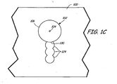
- FIG. 1C is a schematic plan view of the part of FIGS. 1A-1B after finishing processes.
- FIG. 2A is a schematic plan view of a complex repair pattern for a hole in a part with circumferential damage and a crack.
- FIG. 2B is a schematic plan view of the part of FIG. 2A after a filler material has been welded to the part.
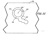
- FIG. 2C is a schematic plan view of the part of FIGS. 2A-2B after finishing processes.
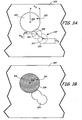
- FIG. 3A is a schematic plan view of a repair pattern for a hole in a part with a crack.
- FIG. 3B is a schematic plan view of the part of FIG. 3A after a filler material has been welded to the part, and with a substantially solid insert positioned within the hole.
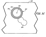
- FIG. 3C is a schematic plan view of a filler material welded to a part with a hole in a chain link repair pattern, and a hollow insert positioned within the hole.
- Metal parts having bolt holes, rivet holes, and other similar holes and openings can become worn, corroded, or otherwise oversized or damaged. Damage at or near such holes can include circumferential damage, cracks, corrosion, pitting, elongation, etc. due to localized wear. Such damage can be repaired to return the part, and more specifically the hole formed in the part, back to desired specifications (i.e., returning the hole to blueprint specifications). According to this disclosure, the damage can be removed by first conducting suitable material removal processes, and then welding the part with additional material to provide a hole with desired characteristics (e.g., size, shape and location). In some situations, additional finishing steps, such as additional machining, may be conducted to complete the repair process.
- NDI nondestructive inspection
- FPI fluorescent penetrant inspection
- ultrasonic and x-ray techniques etc.
- FIG. 1A is a schematic representation of part 100 with substantially circular hole 102 therethrough, which is defined by hole centerline axis 104 and hole perimeter 106 at radius R H about axis 104.
- Part 100 may be a stator flange of the inner case of a gas turbine engine.
- Crack 108 in part 100 extends from perimeter 106 of hole.
- a chain of overlapping apertures, or the chain-link shaped pattern 110, is established around crack 108.
- pattern centerline axes 112, 114, and 116 are collinear with hole centerline axis 104.
- An inner edge of pattern 110 at first chain link perimeter 118 is defined by a portion of hole perimeter 106.
- Crack 108 is located entirely within pattern 110.
- Radii Rp 1 , Rp 2 , and Rp 3 are smaller than radius R H , and are illustrated as being approximately equal, although such a relationship is not required and radii Rp 1 , Rp 2 , and Rp 3 will vary depending on the size and location of crack 108.
- pattern perimeters 118, 120, and 122 are illustrated as being generally circular, other shapes such as ovals may be utilized as necessary to obtain removal of the entire crack.
- Material of part 100 is removed within pattern 110, which removes all of the material of part 100 containing crack 108.
- Material can be removed by machining (e.g., using a reamer, drill bit, or other tooling), or any other suitable material removal processes used to create apertures in a base material.
- pattern 110 can be defined in reference to desired tooling for removing material of part 100, for instance, a desired drill bit. It is generally desired that removal of base material of part 100 (i.e., the parent material) be reduced. In other words, it is desired to leave as much of part 100 intact as is possible, while still removing crack 108 in its entirety.
- first link pattern 118 is removed first and acts as a pilot hole, followed by the removal of second link pattern 120 and third link pattern 122.
- base material within third link pattern 122 may be removed prior to removal of base material of second link pattern 120 and first link pattern 118.
- material may be removed from all three chain link patterns 118, 120, and 122 simultaneously.
- weld material 124 is welded to part 100 to fill at least a portion 126 of pattern 110.
- the weld material fills at least a part of the pattern 110 where material of part 100 was removed to at least approximately define hole 102 with desired specifications.
- conductive heat resistance welding can be used. Examples of conductive heat resistance welding processes are found in U.S. Pat. Nos. 6,545,244 , 6,281,467 , and 7,141,754 .
- Weld material 124 is a weldable material selected according to the desired application, and can be the same material as part 100 or another material.
- suitable combinations of base material (i.e., the parent material) and weld material (i.e., the filler) are: Inconel® 718 (base material) and Inconel® 718 (filler); Ti-6Al-4V (base material) and commercially pure Ti (filler) or Ti-6Al-4V (filler); Al 6061 (base material) and Al 4043 (filler); Thermospan® alloy (a low-expansion, precipitation hardenable iron-based alloy available from Carpenter Technology Corp., Wyomissing, PA) (base material) and Inconel® 625 (filler) or Thermospan® alloy (filler); and Waspaloy (a nickel-base, precipitation hardenable alloy) (base material) and Waspaloy (filler).
- portion 126 is created by commencing the weld to fill third link pattern 122, followed by filling of second link pattern 120 and first link pattern 118.
- Starting with third link pattern 122 assures that the beginning of the weld has adequate base material to which the filler material can bond.
- the weld is started adjacent hole 102, and first chain link pattern 118 is filled prior to the filling of second link pattern 120 and third link pattern 122. This allows for creation of the weld along the perimeter 106 to minimize the amount finishing of the part to complete the repair. It is possible to weld filler 124 within chain link patterns 118, 120, and 122 in separate steps. Machining can be performed between such separate welding steps.
- weld material 124 i.e., the filler
- weld material 124 will not be formed to final specifications and tolerances immediately following the welding process, such as shown in FIG. 1B .
- additional finishing steps can be conducted.
- excess weld material 128 may be present within a perimeter of a desired hole location 130.
- Excess weld material 128 can be removed by machining (e.g., using a reamer, drill bit, or other tooling), or other material removal processes.
- hole 102 substantially matches desired hole location 130, as shown in FIG. 1C .
- a metal part may have multiple types of damage.
- a part may have non-discrete damage (e.g., corrosion damage over a significant area) as well as discrete damage (e.g., multiple localized cracks) near a hole.
- a metallic part with multiple types of damage can be repaired using a complex repair pattern made up of a plurality of repair patterns or repair pattern regions.
- FIG. 2A is a schematic representation of part 200 with desired hole location 202 indicated thereon, which is defined by hole centerline axis 204 and hole perimeter 206 at radius R H about axis 204. Corroded hole perimeter 207 is located near desired hole location 202. As shown in FIG.
- a hole originally formed at desired hole location 202 has circumferential corrosion, which has enlarged the original hole slightly and produced an irregular shaped hole defined by corroded hole perimeter 207. Crack 208 in part 200 extends from corroded hole perimeter 207.
- Chain link repair pattern 210 is defined by first pattern perimeter 209 at radius Rp 4 about hole centerline axis 204, which is coaxial with desired hole location 202. Radius Rp 4 is larger than radius R H , such that first pattern 209 encompasses all of corroded hole perimeter 207. Smaller, generally circular, chain link patterns 218, 220, and 222 define the rest of chain link repair pattern 210. Chain link patterns 218, 220, and 222 are each located around a portion of crack 208, starting at first chain link pattern perimeter 218 and ending with third chain link pattern perimeter 222, such that all of crack 208 is located within chain link repair pattern 210.
- Chain link pattern perimeters 218, 220, and 222 each which have a respective radius Rp 5 , Rp 6 , and Rp 7 , about axes 212, 214, and 216.
- First chain link pattern centerline axis 212 is spaced from hole centerline axis 204, and is located outside of hole perimeter 206 and first pattern perimeter 209.
- Second link pattern centerline 214 is located outside of first link pattern 218, and third link pattern centerline 216 is located outside of second link pattern 220.
- pattern centerline axes 212, 214, and 216 are generally collinear with respect to one another, but not with respect to hole centerline axis 204.
- Crack 208 is a compound nonlinear crack.
- An inner edge of first chain link perimeter 218 is defined by a portion of first pattern perimeter 209.
- Crack 208 and corroded hole perimeter 207 are located entirely within pattern 210.
- Radii R P5 , R P6 , and R P7 are smaller than radius R H (and thus R p4 ), and are illustrated as being approximately equal, although such a relationship is not required and radii R P5 , R P6 , and R P7 will vary depending on the size and location of crack 208.
- pattern centerline axes 212, 214, and 216 may have a nonlinear relationship to one another.
- Material of part 200 is removed within pattern 210, which first removes material of part 200 in which corroded perimeter 207 is defined. Material of part 200 is then removed within chain link pattern perimeters 218, 220, and 222, which removes material of part 200 containing a portion of crack 208 (i.e., the portion of crack 208 not contained in first pattern perimeter 209). In an alternate embodiment, material may be removed within chain link pattern perimeters 218, 220, and 222 prior to removal of base material of part 200 within first pattern perimeter 209. Material can be removed by machining (e.g., using a reamer, drill bit, or other tooling), cutting, or other material removal processes. In further embodiments, additional patterns can be defined on part 200. The particular number, shape, and arrangement of material removal patterns will vary depending on the particular types of damage to base material of part 200.
- weld material 224 (i.e., the filler) material is welded within at least a portion 226 of repair pattern 210 as shown in FIGS. 2A & 2B .
- This welding process can be generally similar to that described above with respect to FIGS. 1A-1C .
- the weld material 224 is generally welded within first pattern 209 and chain link patterns 218, 220, and 222 at the same time. However, it is possible to weld filler 224 within chain link patterns 218, 220, and 222, and then separately weld filler 224 within first pattern 209, or vice versa. Machining can be performed between such separate welding steps.
- finishing processes can be conducted as needed. For example, machining can be conducted as described above with respect to FIGS. 1A-1C in order to form a finished hole through part 200 according to desired specifications (i.e., to blueprint specifications). As shown in FIG. 2C , finished hole 232 substantially matches desired hole location 202.
- an insert i.e. a weld backing
- a weld backing can be used during welding in order to reduce and preferably eliminate the need for post-weld finishing, such as post-weld machining.
- the damage is first identified and material of the part is then removed around the location of the damage, as described above. Then, generally prior to welding the filler to the part, an insert is positioned within the hole.
- FIG. 3A is a schematic representation of part 300 having hole 302 defined therethrough.
- Hole 302 is defined by hole centerline axis 304 and hole perimeter 306 at radius R H about axis 304.
- Crack 308 extends from hole perimeter 306.
- Chain link repair pattern 310 which is defined by first chain perimeter 318 and second chain perimeter 320, is located at hole perimeter 306.
- pattern centerline axes 312 and 314 are noncollinear with hole centerline axis 104, although a portion of hole 306, first chain perimeter 318, and second chain perimeter 320 all overlap with the adjacent aperture.
- Radii Rp 8 and Rp 9 of first chain perimeter 18 and second chain perimeter 320 are smaller than radius R H , and the cumulative value is approximately equal to R H , although such a relationship is not required.
- R P8 is greater in diameter than R P9. while in other embodiments R P8 is smaller in diameter than R P9 .
- FIG. 3B is a schematic representation of part 300 after base material has been removed within pattern 310.
- Substantially solid insert 334 is positioned within hole 302.
- Insert 334 is formed to the desired dimensions of desired hole shape 302.
- Insert 334 can be constructed of any suitable material, such as, for example, a common casting core, a refractory metal or a quartz weld backing, commonly known within the art.
- Insert 334 can be provided in the form of a pre-shaped solid material, or provided as a formable paste made of a powder and a suitable binder. Insert 334 should have a melting temperature greater than filler or weld material 324.
- Weld material 324 is welded where material was removed from pattern 310.
- Weld material 324 abuts part 300 and insert 334.
- Insert 334 acts like a casting mold during the welding process in order to form weld material 324 in a desired shape as weld material 324 becomes flowable during welding. This more closely provides desired hole specifications during the welding process, while reducing and preferably eliminating the need for post-weld finishing (e.g., machining of the weld material to desired hole specifications). Some machining may be necessary for the surfaces of the part adjacent the hole to remove excess material added by the welding process, but the hole itself will not require post-weld finishing.
- FIG. 3C is a schematic representation of hollow insert 336 positioned within hole 302 (defined by hole centerline axis 304 and hole perimeter 306) in part 300, with weld material 324 in chain link pattern 310 defined adjacent to hole 302.
- Hollow insert 336 is generally similar to substantially solid insert 334 shown and described with respect to FIG. 3B .
- a repair made as described contains several advantages.
- the amount of base material removed by the process of creating a chain of holes is much less than that done by many prior art methods utilizing a single hole material removal process. This leaves a greater structural integrity of the base part over the prior art methods.
- the removal of material in a chain of small generally circular holes allows for the use of simple pre-existing equipment without the necessity of a large amount of new tooling.
- the method allows for discrete removal of material along a localized crack in a small area. Thus, if further cracks develop at different locations along the hole, the repair technique may be utilized multiple times to repair these cracks, either at the same time or in the future should further defects be later detected in the part.
- the removal method as disclosed allows for repair of multiple longer cracks emanating from random locations adjacent a hole than provided in prior art techniques. Creating a chain of smaller material removals versus a single hole removal minimizes melting of the base material, thus assuring structural integrity of the part.
Landscapes
- Engineering & Computer Science (AREA)
- Mechanical Engineering (AREA)
- Arc Welding In General (AREA)
Claims (12)
- Procédé de réparation d'un défaut adjacent à un trou (102), le procédé comprenant :le retrait d'au moins un défaut adjacent à un trou souhaité dans un matériau de base par retrait d'une première portion (118) du matériau de base à proximité du trou souhaité ;le retrait d'une seconde portion (124) du matériau de base à proximité de la première portion,où les première et seconde portions créent une chaîne d'ouvertures chevauchantes adjacentes au trou souhaité ; caractérisé en ce qu'il comprend en outre :le soudage d'un matériau de charge (120) sur le matériau de base après retrait des première et seconde portions de matériau de base.
- Procédé selon la revendication 1, dans lequel le processus de soudage utilisé est le soudage conducteur de résistance à la chaleur.
- Procédé selon l'une de la revendication 1 ou 2, et comprenant en outre le retrait d'une portion du matériau de charge jusqu'à l'obtention de la forme du trou souhaité.
- Procédé selon la revendication 1, 2 ou 3, dans lequel le retrait de la première et/ou seconde portions du matériau de base est effectué par perçage d'un trou dans le matériau de base.
- Procédé selon la revendication 1, 2, 3 ou 4, et comprenant en outre :le positionnement d'une garniture (334, 336) par rapport au trou souhaité dans le matériau de base avant le soudage du matériau de charge (124), où la garniture définit sensiblement le trou souhaité pour le soudage du matériau de charge au niveau d'une portion de périmètre du trou souhaité ; et de préférence où le trou souhaité est défini par la garniture dans le matériau de base après soudage du matériau de charge, sans nécessiter d'usinage après soudage du trou lui-même.
- Procédé selon la revendication 5, et comprenant en outre :le retrait de la garniture (334, 336).
- Procédé selon l'une quelconque des revendications précédentes, le procédé comprenant :la création d'une ouverture sensiblement circulaire (209) dans la partie qui a un diamètre plus grand que le trou souhaité, où des axes centraux (204) du trou souhaité et de l'ouverture sont alignés ;où la première ouverture et les première (218) et seconde (220) portions sont contiguës.
- Procédé selon la revendication 7, dans lequel l'ouverture (209) est créée avant le retrait des première (218) et seconde (220) portions.
- Procédé selon la revendication 7 ou 8, dans lequel le retrait de la première portion forme une seconde ouverture (218) qui est sensiblement circulaire et comporte un axe central (212), et où l'axe central (204) de la seconde ouverture est espacé de l'axe central de la première ouverture.
- Procédé selon la revendication 7, 8 ou 9, et comprenant en outre :l'identification d'un dommage circonférentiel (207) infligé à une partie d'une circonférence du trou sensiblement circulaire dans la pièce.
- Procédé selon la revendication 7, 8, 9 ou 10, dans lequel l'axe central (204) de trou, l'axe central (212) de premier motif et l'axe central (214) de second motif sont colinéaires les uns par rapport aux autres ; dans lequel, en variante, l'axe central (204) de trou, l'axe central (212) de premier motif et l'axe central (214) de second motif ne sont pas colinéaires.
- Procédé selon l'une quelconque des revendications précédentes, dans lequel la première portion (118) est retirée avant le retrait de la seconde portion (120).
Applications Claiming Priority (1)
| Application Number | Priority Date | Filing Date | Title |
|---|---|---|---|
| US12/080,701 US9227278B2 (en) | 2005-10-13 | 2008-04-04 | Bolt hole repair technique |
Publications (2)
| Publication Number | Publication Date |
|---|---|
| EP2106875A1 EP2106875A1 (fr) | 2009-10-07 |
| EP2106875B1 true EP2106875B1 (fr) | 2011-02-23 |
Family
ID=40823168
Family Applications (1)
| Application Number | Title | Priority Date | Filing Date |
|---|---|---|---|
| EP09250882A Not-in-force EP2106875B1 (fr) | 2008-04-04 | 2009-03-27 | Technique de réparation de trous |
Country Status (3)
| Country | Link |
|---|---|
| US (1) | US9227278B2 (fr) |
| EP (1) | EP2106875B1 (fr) |
| DE (1) | DE602009000756D1 (fr) |
Cited By (1)
| Publication number | Priority date | Publication date | Assignee | Title |
|---|---|---|---|---|
| RU2532577C2 (ru) * | 2013-03-01 | 2014-11-10 | Федеральное государственное унитарное предприятие "Научно-производственное объединение им. С.А. Лавочкина" | Способ исправления дефектов металлоконструкций |
Families Citing this family (13)
| Publication number | Priority date | Publication date | Assignee | Title |
|---|---|---|---|---|
| US8895887B2 (en) * | 2011-08-05 | 2014-11-25 | General Electric Company | Resistance weld repairing of casing flange holes |
| CN103481008B (zh) * | 2013-09-05 | 2017-01-25 | 通裕重工股份有限公司 | 一种深孔焊补工艺 |
| CN105149360A (zh) * | 2015-06-30 | 2015-12-16 | 江苏永钢集团有限公司 | 一种快速修复在线齿轮箱轴承孔的方法 |
| US10265810B2 (en) | 2015-12-03 | 2019-04-23 | General Electric Company | System and method for performing an in situ repair of an internal component of a gas turbine engine |
| CN106002081A (zh) * | 2016-06-27 | 2016-10-12 | 共享铸钢有限公司 | 马氏体耐热钢螺纹孔缺陷修复方法 |
| US10989223B2 (en) | 2017-02-06 | 2021-04-27 | General Electric Company | Coated flange bolt hole and methods of forming the same |
| EP3628477B1 (fr) * | 2018-09-28 | 2021-03-31 | Siemens Gamesa Renewable Energy A/S | Procédé de réparation d'une racine de pale de rotor d'une éolienne |
| CN109764120A (zh) * | 2019-01-25 | 2019-05-17 | 天津华建天恒传动有限责任公司 | 一种风电齿轮箱输出轴壳体轴承位空修复方法 |
| CN114523258A (zh) * | 2020-11-23 | 2022-05-24 | 华域皮尔博格有色零部件(上海)有限公司 | 一种压铸模具冷薄壁破损区域的修理方法 |
| CN114932304A (zh) * | 2022-04-28 | 2022-08-23 | 国营四达机械制造公司 | 一种零件孔侧壁掉块缺陷的搅拌摩擦焊修复方法 |
| CN114932305B (zh) * | 2022-04-28 | 2023-05-12 | 国营四达机械制造公司 | 一种零件孔侧壁裂纹缺陷的搅拌摩擦焊修复方法 |
| CN114888387B (zh) * | 2022-06-29 | 2024-10-01 | 中国航发动力股份有限公司 | 一种涡轮工作叶片工艺孔的真空钎焊装置及方法 |
| FR3160119A1 (fr) * | 2024-03-12 | 2025-09-19 | Safran Landing Systems | Procédé de réparation de pièces présentant un trou et dont la surface bordant le trou est détériorée |
Family Cites Families (18)
| Publication number | Priority date | Publication date | Assignee | Title |
|---|---|---|---|---|
| US2120525A (en) | 1937-06-01 | 1938-06-14 | Thomas J Mckerihan | Method of building up pitted holes in a metal sheet |
| US3066400A (en) * | 1959-02-18 | 1962-12-04 | Ronald S Forsythe | Method of repairing metal castings |
| US3246392A (en) | 1965-07-01 | 1966-04-19 | George A Altgelt | Method of repairing aircraft cylinder heads |
| US3576065A (en) * | 1969-03-24 | 1971-04-27 | Chromalloy American Corp | Repair of apertured machine components |
| US3740820A (en) | 1971-01-28 | 1973-06-26 | R Tarves | Method of repairing damaged holes in a boiler drum |
| SU548400A1 (ru) | 1975-01-23 | 1977-02-28 | Волжский Ордена Трудового Красного Знамени Завод Цементного Машиностроения | Способ исправлени дефектов |
| US4953777A (en) | 1986-10-08 | 1990-09-04 | Chromalloy Gas Turbine Corporation | Method for repairing by solid state diffusion metal parts having damaged holes |
| US5111570A (en) | 1990-08-10 | 1992-05-12 | United Technologies Corporation | Forge joining repair technique |
| US5201455A (en) | 1992-08-21 | 1993-04-13 | Westinghouse Electric Corp. | Method for metallurgical enhancement of a failed bolt hole |
| US5606797A (en) | 1995-06-26 | 1997-03-04 | Reynolds; Russell B. | Process to restore and refurbish turbocharger housing |
| US6545244B1 (en) | 1997-09-16 | 2003-04-08 | Edison Welding Institute | Conductive heat seam welding |
| CA2303336C (fr) | 1997-09-16 | 2006-11-21 | Edison Welding Institute | Soudage continu par resistance thermique conductrice |
| US6490791B1 (en) | 2001-06-22 | 2002-12-10 | United Technologies Corporation | Method for repairing cracks in a turbine blade root trailing edge |
| US6742698B2 (en) | 2002-06-10 | 2004-06-01 | United Technologies Corporation | Refractory metal backing material for weld repair |
| US7146725B2 (en) * | 2003-05-06 | 2006-12-12 | Siemens Power Generation, Inc. | Repair of combustion turbine components |
| US7028881B2 (en) | 2003-09-18 | 2006-04-18 | Siemens Power Generation, Inc. | Method for providing removable weld backing |
| US7141754B2 (en) * | 2004-02-05 | 2006-11-28 | Edison Welding Institute, Inc. | Method for repairing defects in a conductive substrate using welding |
| US7552855B2 (en) | 2005-10-13 | 2009-06-30 | United Technologies Corporation | Hole repair technique and apparatus |
-
2008
- 2008-04-04 US US12/080,701 patent/US9227278B2/en not_active Expired - Fee Related
-
2009
- 2009-03-27 EP EP09250882A patent/EP2106875B1/fr not_active Not-in-force
- 2009-03-27 DE DE602009000756T patent/DE602009000756D1/de active Active
Cited By (1)
| Publication number | Priority date | Publication date | Assignee | Title |
|---|---|---|---|---|
| RU2532577C2 (ru) * | 2013-03-01 | 2014-11-10 | Федеральное государственное унитарное предприятие "Научно-производственное объединение им. С.А. Лавочкина" | Способ исправления дефектов металлоконструкций |
Also Published As
| Publication number | Publication date |
|---|---|
| DE602009000756D1 (de) | 2011-04-07 |
| EP2106875A1 (fr) | 2009-10-07 |
| US9227278B2 (en) | 2016-01-05 |
| US20090250441A1 (en) | 2009-10-08 |
Similar Documents
| Publication | Publication Date | Title |
|---|---|---|
| EP2106875B1 (fr) | Technique de réparation de trous | |
| EP1775061B1 (fr) | Technique de réparation d'un trou | |
| CN100420537C (zh) | 焊接修复部件的方法 | |
| EP3062952B1 (fr) | Réusinage de soudure au laser par dépôt de poudre pour moulages de nickel pouvant être soudés sans fusion pour turbine à gaz | |
| EP1844888A1 (fr) | Procédé de soudage dans un composanr en superalliage ou de réparation d'une fissure dans un composant en superalliage utilisant le brasage après le soudage | |
| EP1074331A1 (fr) | Procédé de réparation des pièces coulées en superalliage en utilisant un bouchon conique fixé par liason métallurgique | |
| JPS6234671A (ja) | 低合金鋼製ロ−タの修理方法 | |
| US8245375B2 (en) | Apparatus for repairing turbine rotor | |
| US20160045982A1 (en) | Hybrid welding/printing process | |
| US6327766B1 (en) | Method for repairing studs fixed to a cover for a transmission torque connector | |
| JP6581498B2 (ja) | タービンロータディスクの補修方法 | |
| US10272519B2 (en) | Conical pins for the structural repair of defects | |
| JP5535799B2 (ja) | 金属部品の補修方法及び補修された金属部品 | |
| EP1605068A2 (fr) | Soudage homogène au moyen de préchauffage pour superalliage à haute résistance et dépôt de matière | |
| EP2983858B1 (fr) | Pistons réparés et leur collecte | |
| US20080011812A1 (en) | Integral backing ring for stub shaft weld repairs of rotating equipment and related method | |
| EP2808487B1 (fr) | Procédé pour fermer une ouverture sur une pale d'une turbine à gaz | |
| JPH06159007A (ja) | 損傷されたボルト孔の冶金的強化方法 | |
| EP2020274A1 (fr) | Appareil et procédé de réparation de pointes de surface portante | |
| JPH05263603A (ja) | タービンブレードの修理のための部品及び方法 | |
| JPS6055236B2 (ja) | 非鉄合金の補修溶接方法 | |
| CN113226611A (zh) | 焊接-钎焊技术 |
Legal Events
| Date | Code | Title | Description |
|---|---|---|---|
| PUAI | Public reference made under article 153(3) epc to a published international application that has entered the european phase |
Free format text: ORIGINAL CODE: 0009012 |
|
| AK | Designated contracting states |
Kind code of ref document: A1 Designated state(s): AT BE BG CH CY CZ DE DK EE ES FI FR GB GR HR HU IE IS IT LI LT LU LV MC MK MT NL NO PL PT RO SE SI SK TR |
|
| AX | Request for extension of the european patent |
Extension state: AL BA RS |
|
| 17P | Request for examination filed |
Effective date: 20091222 |
|
| 17Q | First examination report despatched |
Effective date: 20100303 |
|
| AKX | Designation fees paid |
Designated state(s): DE GB |
|
| GRAP | Despatch of communication of intention to grant a patent |
Free format text: ORIGINAL CODE: EPIDOSNIGR1 |
|
| RIC1 | Information provided on ipc code assigned before grant |
Ipc: B23P 6/04 20060101AFI20100929BHEP |
|
| GRAS | Grant fee paid |
Free format text: ORIGINAL CODE: EPIDOSNIGR3 |
|
| GRAA | (expected) grant |
Free format text: ORIGINAL CODE: 0009210 |
|
| AK | Designated contracting states |
Kind code of ref document: B1 Designated state(s): DE GB |
|
| REG | Reference to a national code |
Ref country code: GB Ref legal event code: FG4D |
|
| REF | Corresponds to: |
Ref document number: 602009000756 Country of ref document: DE Date of ref document: 20110407 Kind code of ref document: P |
|
| REG | Reference to a national code |
Ref country code: DE Ref legal event code: R096 Ref document number: 602009000756 Country of ref document: DE Effective date: 20110407 |
|
| PLBE | No opposition filed within time limit |
Free format text: ORIGINAL CODE: 0009261 |
|
| STAA | Information on the status of an ep patent application or granted ep patent |
Free format text: STATUS: NO OPPOSITION FILED WITHIN TIME LIMIT |
|
| 26N | No opposition filed |
Effective date: 20111124 |
|
| REG | Reference to a national code |
Ref country code: DE Ref legal event code: R097 Ref document number: 602009000756 Country of ref document: DE Effective date: 20111124 |
|
| PGFP | Annual fee paid to national office [announced via postgrant information from national office to epo] |
Ref country code: DE Payment date: 20120411 Year of fee payment: 4 |
|
| GBPC | Gb: european patent ceased through non-payment of renewal fee |
Effective date: 20130327 |
|
| REG | Reference to a national code |
Ref country code: DE Ref legal event code: R119 Ref document number: 602009000756 Country of ref document: DE Effective date: 20131001 |
|
| PG25 | Lapsed in a contracting state [announced via postgrant information from national office to epo] |
Ref country code: DE Free format text: LAPSE BECAUSE OF NON-PAYMENT OF DUE FEES Effective date: 20131001 Ref country code: GB Free format text: LAPSE BECAUSE OF NON-PAYMENT OF DUE FEES Effective date: 20130327 |