EP2107510A1 - Verfahren und Vorrichtung zur Ausgabe von drahtlosen IC-Etiketten - Google Patents
Verfahren und Vorrichtung zur Ausgabe von drahtlosen IC-Etiketten Download PDFInfo
- Publication number
- EP2107510A1 EP2107510A1 EP09002759A EP09002759A EP2107510A1 EP 2107510 A1 EP2107510 A1 EP 2107510A1 EP 09002759 A EP09002759 A EP 09002759A EP 09002759 A EP09002759 A EP 09002759A EP 2107510 A1 EP2107510 A1 EP 2107510A1
- Authority
- EP
- European Patent Office
- Prior art keywords
- wireless
- tag
- antenna
- data
- written
- Prior art date
- Legal status (The legal status is an assumption and is not a legal conclusion. Google has not performed a legal analysis and makes no representation as to the accuracy of the status listed.)
- Withdrawn
Links
Images






Classifications
-
- B—PERFORMING OPERATIONS; TRANSPORTING
- B41—PRINTING; LINING MACHINES; TYPEWRITERS; STAMPS
- B41J—TYPEWRITERS; SELECTIVE PRINTING MECHANISMS, i.e. MECHANISMS PRINTING OTHERWISE THAN FROM A FORME; CORRECTION OF TYPOGRAPHICAL ERRORS
- B41J3/00—Typewriters or selective printing or marking mechanisms characterised by the purpose for which they are constructed
- B41J3/407—Typewriters or selective printing or marking mechanisms characterised by the purpose for which they are constructed for marking on special material
-
- B—PERFORMING OPERATIONS; TRANSPORTING
- B41—PRINTING; LINING MACHINES; TYPEWRITERS; STAMPS
- B41J—TYPEWRITERS; SELECTIVE PRINTING MECHANISMS, i.e. MECHANISMS PRINTING OTHERWISE THAN FROM A FORME; CORRECTION OF TYPOGRAPHICAL ERRORS
- B41J3/00—Typewriters or selective printing or marking mechanisms characterised by the purpose for which they are constructed
- B41J3/44—Typewriters or selective printing mechanisms having dual functions or combined with, or coupled to, apparatus performing other functions
- B41J3/50—Mechanisms producing characters by printing and also producing a record by other means, e.g. printer combined with RFID writer
-
- G—PHYSICS
- G06—COMPUTING OR CALCULATING; COUNTING
- G06K—GRAPHICAL DATA READING; PRESENTATION OF DATA; RECORD CARRIERS; HANDLING RECORD CARRIERS
- G06K17/00—Methods or arrangements for effecting co-operative working between equipments covered by two or more of main groups G06K1/00 - G06K15/00, e.g. automatic card files incorporating conveying and reading operations
-
- G—PHYSICS
- G06—COMPUTING OR CALCULATING; COUNTING
- G06K—GRAPHICAL DATA READING; PRESENTATION OF DATA; RECORD CARRIERS; HANDLING RECORD CARRIERS
- G06K17/00—Methods or arrangements for effecting co-operative working between equipments covered by two or more of main groups G06K1/00 - G06K15/00, e.g. automatic card files incorporating conveying and reading operations
- G06K17/0022—Methods or arrangements for effecting co-operative working between equipments covered by two or more of main groups G06K1/00 - G06K15/00, e.g. automatic card files incorporating conveying and reading operations arrangements or provisions for transferring data to distant stations, e.g. from a sensing device
- G06K17/0025—Methods or arrangements for effecting co-operative working between equipments covered by two or more of main groups G06K1/00 - G06K15/00, e.g. automatic card files incorporating conveying and reading operations arrangements or provisions for transferring data to distant stations, e.g. from a sensing device the arrangement consisting of a wireless interrogation device in combination with a device for optically marking the record carrier
-
- G—PHYSICS
- G06—COMPUTING OR CALCULATING; COUNTING
- G06K—GRAPHICAL DATA READING; PRESENTATION OF DATA; RECORD CARRIERS; HANDLING RECORD CARRIERS
- G06K19/00—Record carriers for use with machines and with at least a part designed to carry digital markings
- G06K19/06—Record carriers for use with machines and with at least a part designed to carry digital markings characterised by the kind of the digital marking, e.g. shape, nature, code
- G06K19/067—Record carriers with conductive marks, printed circuits or semiconductor circuit elements, e.g. credit or identity cards also with resonating or responding marks without active components
- G06K19/07—Record carriers with conductive marks, printed circuits or semiconductor circuit elements, e.g. credit or identity cards also with resonating or responding marks without active components with integrated circuit chips
- G06K19/077—Constructional details, e.g. mounting of circuits in the carrier
- G06K19/07718—Constructional details, e.g. mounting of circuits in the carrier the record carrier being manufactured in a continuous process, e.g. using endless rolls
Definitions
- the present invention relates to a method and an apparatus which issue a wireless IC tag used in the fields of merchandise management, distribution management, and the like.
- RFID radiofrequency identification
- a reader/writer which can wirelessly communicate with the wireless IC tag is connected to a host apparatus.
- the reader/writer wirelessly communicates with the wireless IC tag attached to each of the individual pieces to specify the wireless IC tag.
- the host apparatus identifies the individual piece to which the wireless IC tag specified by the reader/writer is attached.
- a wireless IC tag for individual recognition generally has a structure in which a wireless communication circuit is embedded in a label body or a card body.
- the wireless communication circuit is called an inlet and includes an IC chip and an antenna.
- an inlet is sandwiched between a sheet to be printed and released paper.
- a nonvolatile memory is mounted in the IC chip.
- the memory stores information or the like to specify the wireless IC tag.
- the information stored in the memory is electronic information. For this reason, a user of the wireless IC tag cannot visually check the information in the memory. Therefore, in the wireless IC tag for individual recognition, information in the memory or information which can recognize the information in the memory is generally printed on the surface of a label or a card. In this manner, the user can easily recognize information in the memory.
- a wireless IC tag issuing apparatus which issues a wireless IC tag for individual recognition is already in practical use.
- the apparatus includes conveying means for sequentially conveying a plurality of wireless IC tags.
- the apparatus wirelessly communicates with a wireless IC tag conveyed by the conveying means to write necessary information to a memory of the wireless IC tag.
- the apparatus operates a printer to print the necessary information on the surface of the wireless IC tag.
- Jpn. Pat. Appln. KOKAI Publication No. 2003-132330 or 2006-040023 discloses a wireless IC tag issuing apparatus in which a plurality of antennas are arranged on conveying paths for a wireless IC tag.
- an information writing antenna is arranged on an upstream side in a conveying direction of a wireless IC tag, and an information reading antenna is arranged on a downstream side.
- the information writing antenna writes information to the wireless IC tag.
- the information reading antenna reads the information written to the wireless IC tag.
- the apparatus determines whether the information written to the wireless IC tag can be correctly read.
- the apparatus writes necessary information to the subsequent wireless IC tag by the information writing antenna. For this reason, when an information write error to the wireless IC tag is detected, the apparatus writes another piece of information to the subsequent wireless IC tag in advance. Therefore, the apparatus cannot issue a wireless IC tag, in which information to be written to the wireless IC tag having the write error is recorded, subsequently to the wireless IC tag in which the error occurs.
- a wireless IC tag issuing apparatus including conveying means configured to sequentially convey a plurality of wireless IC tags each having an inlet including an IC chip and an antenna includes a first antenna and a second antenna as antennas to perform radio communication with the wireless IC tag.
- the second antenna is arranged on a downstream side in a conveying direction of the wireless IC tag with respect to the first antenna.
- An interval between the first antenna and the second antenna in the wireless IC tag conveying direction is made smaller than a distance between the inlets of sequential wireless IC tags.
- a control unit checks whether data is normally written to the wireless IC tag on the basis of the data written to the wireless IC tag through the first antenna and data read from the wireless IC tag through the second antenna.
- the present invention is applied to a wireless IC tag issuing apparatus to issue an RFID label.
- FIG. 1 A first embodiment will be described below with reference to FIGS. 1 to 7 .
- the configuration of a wireless IC tag issuing apparatus 1 according to the embodiment is shown in the schematic diagram in FIG. 1 .
- the wireless IC tag issuing apparatus 1 includes a control unit 2, an operation panel 3, a communication interface 4, a storage unit 5, a head driver 6, an RFID reader/writer 7, a conveying motor 8, and a sensor signal input unit 9.
- the wireless IC tag issuing apparatus 1 includes a holder to hold a label sheet 10 wound in the form of a roll.
- a conveying roller 11 along a conveying path of the label sheet 10 drawn from the holder, a conveying roller 11, a first antenna 12, a platen roller 13, and a second antenna 14 are sequentially arranged from the upstream side which is a holder side.
- the issuing apparatus 1 is arranged such that a guide roller 15 faces the conveying roller 11.
- the issuing apparatus 1 is arranged such that a print head 16 faces the platen roller 13.
- the label sheet 10 drawn from the holder passes through a portion between the conveying roller 11 and the guide roller 15.
- the label sheet 10 then passes through a portion near the first antenna 12.
- the label sheet 10 passes through a portion between the platen roller 13 and the print head 16. Finally, the label sheet 10 is discharged out of the apparatus through a portion near the second antenna 14.
- the label sheet 10 has a belt-like board 21.
- a large number of wireless IC tags 22 are aligned in a longitudinal direction of the board 21 and releasably stuck.
- the wireless IC tag 22 has an inlet 25 including an IC chip 23 and an antenna 24.
- the inlet 25 is sandwiched between a sheet constituting a front surface of the wireless IC tag 22 and a sheet constituting the rear surface.
- the sheet constituting the rear surface has an adhesive surface, and the sheet constituting the front surface has a print surface.
- the print head 16 prints visible information on the print surface serving as the front surface of the wireless IC tag 22 in response to a signal from the head driver 6.
- a thermal head is used as the print head 16.
- An ink ribbon may be interposed between the print head 16 and the label sheet 10.
- the print head 16 constitutes printing means which is arranged between the first antenna 12 and the second antenna 14 and prints visible information on the front surface of the wireless IC tag 22.
- the conveying roller 11 and the platen roller 13 are rotationally driven by the motive energy of the conveying motor 8.
- the conveying roller 11 and the platen roller 13 are freely rotated forward or backward by switching gears.
- the label sheet 10 is conveyed in a direction of an arrow A in FIG. 1 .
- each of the wireless IC tags 22 on the label sheet 10 passes through an upper portion of the first antenna 12 first.
- the wireless IC tag 22 passes through a portion between the platen roller 13 and the print head 16 and then passes through an upper portion of the second antenna 14.
- the conveying motor 8 constitutes conveying means which sequentially conveys the plurality of wireless IC tags 22 each having the inlet 25 constituted by the IC chip 23 and the antenna 24.
- the first antenna 12 and the second antenna 14 are connected to the RFID reader/writer 7.
- the first antenna 12 has radio-emitting characteristics set such as a radio field intensity and a directivity which are set such that a radio wave emitted from the first antenna 12 is received by the antenna 24 of the wireless IC tag 22 passing right over the antenna 12.
- the second antenna 14 has radio-emitting characteristics set such that a radio wave emitted from the second antenna 14 is received by the antenna 24 of the wireless IC tag 22 passing right over the antenna 14.
- dipole antennas and patch antennas can be used.
- the antennas 12 and 14 can be arbitrarily selected.
- the RFID reader/writer 7 modulates a carrier wave with write data to the wireless IC tag 22 and causes the first antenna 12 to emit the modulated wave as a radio wave. With this radio communication, the RFID reader/writer 7 writes data to the wireless IC tag 22 passing right over the first antenna 12 in a contactless manner.
- the RFID reader/writer 7 demodulates a signal received from the wireless IC tag 22 by the second antenna 14. With the demodulated signal, the RFID reader/writer 7 reads data from the wireless IC tag 22 passing right over the second antenna 14 in a contactless manner.
- the first antenna 12 functions as an information writing antenna.
- the second antenna 14 functions as an information reading antenna.
- the first antenna 12 and the second antenna 14 are arranged on the upstream and downstream sides in the conveying direction of the label sheet 10 to interpose the platen roller 13.
- An interval d1 between the first antenna 12 and the second antenna 14 is designed to be smaller than a distance d2 between the inlets 25 of the subsequent wireless IC tags 22 stuck to the label sheet 10 at equal intervals.
- a plurality of sensors are arranged on the conveying path of the label sheet 10.
- the sensors detect front ends or rear ends of the wireless IC tags 22 sequentially conveyed together with the label sheet 10. Signals detected by the sensors are input to the control unit 2 through the sensor signal input unit 9.
- the control unit 2 is mainly configured by a central processing unit (CPU).
- the operation panel 3 includes an input/output device such as a keyboard and a display.
- a host apparatus to generate label data is connected to the communication interface 4.
- the label data includes individual recognition information written to the memory of the wireless IC tag 22 and visible information printed on the print surface of the wireless IC tag 22.
- the individual recognition information and the visible information have a one-to-one relationship.
- the label data (individual recognition information and visible information) generated by the host apparatus is received by the control unit 2 through the communication interface 4 and sequentially stored in the storage unit 5.
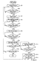
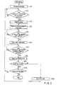
- the control unit 2 controls the units according to procedures shown in the flow chart in FIG. 3 .
- the control procedures are realized by a program stored in the storage unit 5 in advance.
- the issue command is given by an operation input of the operation panel 3 or a command input from the host apparatus.
- the control unit 2 controls the conveying motor 8 to convey the label sheet 10 in a forward direction (direction of arrow A in FIG. 1 ) in step ST1.
- the control unit 2 waits until the inlet 25 of any one of the wireless IC tags 22 reaches a communication position (first antenna position) immediately above the first antenna 12 in step ST2.
- the control unit 2 determines whether the inlet 25 reaches the communication position of the first antenna 12 by a sensor signal input through the sensor signal input unit 9.
- the control unit 2 When the inlet 25 reaches the communication position of the first antenna 12, the control unit 2 reads one of tag data stored in the storage unit 5 in a storage order in step ST3. Each time the tag data is read, the control unit 2 transmits individual recognition information of the tag data to the RFID reader/writer 7 in step ST4. The RFID reader/writer 7 writes the individual recognition information to the memory of the inlet 25 reaching the communication position of the first antenna 12 by using radio communication.
- the control unit 2 waits until the front end of the wireless IC tag 22 to which the individual recognition information is written reaches a print position (printer position) by the print head 16 in step ST5.
- the control unit 2 determines whether the front end of the wireless IC tag 22 reaches the print position by a sensor signal input through the sensor signal input unit 9.
- the control unit 2 transmits visible information of tag data corresponding to the individual recognition information to the head driver 6 in step ST6.
- the head driver 6 drives the print head 16.
- the print head 16 prints the visible information on a print surface serving as the front surface of the wireless IC tag 22.
- the control unit 2 waits until the inlet 25 of the wireless IC tag 22 on which the visible information is printed reaches a communication position (second antenna position) immediately above the second antenna 14 in step ST7.
- the control unit 2 determines whether the inlet 25 reaches the communication position of the second antenna 14 by the sensor signal input through the sensor signal input unit 9.
- the control unit 2 When the inlet 25 reaches the communication position of the second antenna 14, the control unit 2 outputs an inquiry command of the tag memory data to the RFID reader/writer 7 in step ST8.
- the RFID reader/writer 7 reads the data stored in the memory of the inlet 25 reaching the communication position of the second antenna 14 by using radio communication. The read data is input to the control unit 2 through the RFID reader/writer 7.
- the control unit 2 determines whether data is normally written to the wireless IC tag 22 in step ST9. More specifically, the control unit 2 collates the tag memory data read from the wireless IC tag 22 with the individual recognition information of the tag data read from the storage unit 5 by the process in step ST3 to determine whether the tag memory data is matched with the individual recognition information.
- both the data are matched with each other.
- the control unit 2 determines that the data is normally written.
- both the data are not matched with each other.
- the control unit 2 determines a write error.
- control unit 2 determines whether the next tag data is stored in the storage unit 5 in step ST10. When the next tag data is stored, the control unit 2 returns to step ST2. The control unit 2 waits until the inlet 25 of any one of the wireless IC tags 22 reaches a communication position immediately above the first antenna 12. When the inlet 25 reaches the communication position of the first antenna 12, the processes in the steps subsequent to step ST3 are executed again.
- control unit 2 determines the write error
- the control unit controls the conveying motor 8 to convey the label sheet 10 in the backward direction (direction opposing arrow A in FIG. 1 ) in step ST11.
- the control unit 2 waits until the front end of the wireless IC tag 22 located above the second antenna 14 reaches the print position (printer position) by the print head 16 in step ST12.
- the control unit 2 determines whether the front end of the wireless IC tag 22 reaches the print position by a sensor input through the sensor signal input unit 9.
- control unit 2 controls the conveying motor 8 to convey the label sheet 10 in the forward direction again in step ST13.
- the control unit 2 outputs print data representing a predetermined error mark to the head driver 6 in step ST14.
- the head driver 6 drives the print head 16.
- the print head 16 prints an error mark on the print surface of the wireless IC tag 22.
- the control unit 2 returns to the process in step ST2. More specifically, the control unit 2 waits until the inlet 25 of any one of the wireless IC tags 22 reaches a communication position immediately above the first antenna 12. When the control unit 2 determines that the inlet 25 of the wireless IC tag 22 reaches the communication position of the first antenna 12, the processes in the steps subsequent to step ST3 are executed again.
- the control unit 2 checks whether data is normally written to the wireless IC tag 22 by the procedures in step ST1 to step ST10. When the data is normally written, the control unit 2 issues the wireless IC tag 22.
- the control unit 2 prints a predetermined error mark to issue the wireless IC tag 22.
- the control unit 2 writes the same data as the data written in the error tag in a wireless IC tag 22 subsequent to the error tag by the procedures returning from step ST13 and step ST14 to step ST2.
- the issuing apparatus 1 conveys the label sheet 10 in a direction of an arrow A in FIG. 4 .
- the inlet 25 of wireless IC tag 22-1 reaches the communication position of the first antenna 12, the first antenna 12 performs radio communication between the inlet 25 and the antenna 24.
- the issuing apparatus 1 writes individual recognition information of tag data to a memory mounted on the IC chip 23 of the inlet 25 in a contactless manner.
- the print head 16 When the front end of wireless IC tag 22-1 reaches the print position by the print head 16, the print head 16 operates.
- the print head 16 prints visible information of the tag data on a print surface serving as a front surface of wireless IC tag 22-1.
- the issuing apparatus 1 reads the data written to the memory mounted on the IC chip 23 of the inlet 25 in a contactless manner.
- the issuing apparatus 1 determines whether the data is normally written to wireless IC tag 22-1.
- the issuing apparatus 1 When the data is normally written, the issuing apparatus 1 further conveys the label sheet 10 in the direction of arrow A. As a result, wireless IC tag 22-1 is issued as an RFID label. Individual recognition information of the label data is written to the memory of wireless IC tag 22-1. Visible information related to the label data is printed on the print surface of wireless IC tag 22-1.
- the issuing apparatus 1 conveys the label sheet 10 in the direction opposing the direction of arrow A.
- the issuing apparatus 1 conveys the label sheet 10 again in the direction of arrow A.
- the print head 16 prints a predetermined error mark on a print surface serving as a front surface of wireless IC tag 22-1.
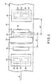
- FIG. 5 shows positional relationships between wireless IC tags 22-0 to 22-2 and the first and second antennas 12 and 14 and the print head 16 obtained immediately before a front end 26 of wireless IC tag 22-1 returns to the print position.
- the label sheet 10 is further conveyed in a direction of an arrow B in FIG. 5 , and the front end 26 of wireless IC tag 22-1 returns to the print position by the print head 16.
- the label sheet 10 is conveyed in a direction opposing the direction of arrow B. Then, a predetermined error mark is printed on the print surface of wireless IC tag 22-1.
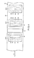
- an interval d1 between the first antenna 12 and the second antenna 14 is smaller than a distance d2 between the inlets 25 of the subsequent wireless IC tags 22 stuck to the label sheet 10 at equal intervals. For this reason, as shown in FIG. 6 , when the inlet 25 of wireless IC tag 22-1 reaches the communication position of the second antenna 14, the inlet 25 of wireless IC tag 22-2 conveyed subsequently to wireless IC tag 22-1 does not reach the communication position of the first antenna 12. Therefore, the individual recognition information of the next tag data is not yet written to wireless IC tag 22-2.
- wireless IC tag 22-1 In the state shown in FIG. 6 , when the write error of wireless IC tag 22-1 is detected, the label sheet 10 is conveyed in a direction opposing the direction of arrow A. When the front end 26 of wireless IC tag 22-1 returns to the print position of the print head 16, the label sheet 10 is conveyed in the direction of arrow A again, and a predetermined error mark is printed on a print surface. Thereafter, wireless IC tag 22-1 passes through the communication position of the second antenna 14 and is issued as an error label.
- the inlet 25 of wireless IC tag 22-2 conveyed subsequently to wireless IC tag 22-1 reaches the communication position of the first antenna 12.
- the inlet 25 of wireless IC tag 22-2 reaches the communication position of the first antenna 12 radio communication is performed between the first antenna 12 and the antenna 24 of the inlet 25.
- individual recognition information to be written to wireless IC tag 22-1 is written to a memory mounted on the IC chip 23 of the inlet 25 of wireless IC tag 22-2 subsequent to wireless IC tag 22-1 in a contactless manner.
- wireless IC tag 22-2 reaches the print position by the print head 16 the print head 16 operates.
- the same visible information as the information printed on wireless IC tag 22-1 is printed on the print surface serving as the surface of wireless IC tag 22-2.
- wireless IC tag 22-2 is issued as an RFID label.
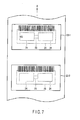
- FIG. 7 shows an example in which wireless IC tag 22-1 is issued as an error label and the subsequent wireless IC tag 22-2 is issued as the RFID label.
- wireless IC tag 22-2 is issued subsequently to wireless IC tag 22-1 serving as the error label.
- Wireless IC tag 22-2 is an RFID label on which individual recognition information and visible information (barcode) to be written to wireless IC tag 22-1 serving as the error label are written.
- a predetermined error mark "NG" is printed on wireless IC tag 22-1 serving as the error label. Therefore, a user of the wireless IC tag issuing apparatus 1 can easily recognize that wireless IC tag 22-1 issued first is an error label and that the subsequently issued wireless IC tag 22-2 is a normal RFID label.
- label data D1, D2, and D3 are given to the wireless IC tag issuing apparatus 1 in the order named.
- the label data D1 is written to wireless IC tag 22-1 issued first.
- the label data D2 is written to wireless IC tag 22-2 issued secondarily.
- the label data D3 is written to a wireless IC tag 22-3 issued thirdly. More specifically, wireless IC tags on which the label data D1, D2, and D3 are recorded in the order named are issued.
- the label data D2 is written to wireless IC tag 22-3 issued thirdly.
- the label data D3 is written to a wireless IC tag 22-4 issued fourth. Therefore, the wireless IC tags on which the label data D1, D2, and D3 are written in the same order as the normal order are issued except for wireless IC tag 22-2 on which the error mark is printed.
- FIG. 8 A second embodiment will be described below with reference to FIGS. 8 and 9 .
- the configuration of the wireless IC tag issuing apparatus 1 according to the second embodiment is shown by a schematic diagram in FIG. 8 .
- the same reference numbers as in FIG. 1 of the first embodiment denote the same parts in the second embodiment, and a description thereof will be briefly described.
- Difference between the second embodiment and the first embodiment includes the following points. That is, mark adding means 31 is arranged facing the second antenna 14, and the drive motor 32 which drives the mark adding means 31 is arranged such that the drive motor 32 can be controlled by the control unit 2.
- the mark adding means 31 sticks a seal to a surface of the wireless IC tag 22 by motive energy of the drive motor 32. On the seal, a predetermined error mark (for example, "NG") is recorded.
- the wireless IC tag 22 to which the seal is stuck is a tag which communicates with the second antenna 14 and which is determined as a write error.
- the mark adding means 31 is not limited to a mechanism which sticks a seal.
- a mechanism which prints an error mark may be used.
- a function which stamps an error mark may be used.
- the control unit 2 when the control unit 2 receives an issue command of an RFID label, the control unit 2 controls the units according to the procedures shown in a flow chart in FIG. 9 .
- the issue command is given by an operation input of the operation panel 3 or a command input from a host apparatus.
- FIG. 9 the same reference numbers as in FIG. 3 of the first embodiment denote the same parts in FIG. 9 , and a detailed description thereof will be omitted.
- the second embodiment is different from the first embodiment in the procedures performed after a write error is determined in the process in step ST9.
- control unit 2 determines the write error
- control unit 2 controls the drive motor 32 to operate the mark adding means 31.
- the mark adding means 31 adds a predetermined error mark to the surface of the wireless IC tag 22 determined as a write error.
- control unit 2 returns to the process in step ST2. More specifically, the control unit 2 waits until the inlet 25 of any one of the wireless IC tags 22 reaches a communication position immediately above the first antenna 12. When the inlet 25 of the wireless IC tag 22 reaches the communication position of the first antenna 12, the control unit 2 executes the processes in the steps subsequent to step ST3 again.
- an interval d1 between the first antenna 12 and the second antenna 14 is smaller than a distance d2 between the inlets 25 of the subsequent wireless IC tags 22 stuck to the label sheet 10 at equal intervals. For this reason, when the inlet 25 of the wireless IC tag 22 reaches the communication position of the second antenna 14, the inlet 25 of the wireless IC tag 22 conveyed subsequently to the wireless IC tag 22 does not reach the communication position of the first antenna 12. Therefore, the individual recognition information of the tag data is not yet written to the subsequent wireless IC tag 22.
- the mark adding means 31 operates to add an error mark to a surface of the wireless IC tag 22, and the wireless IC tag 22 is issued as an error label.
- the inlet 25 of the wireless IC tag 22 conveyed subsequently to the previous wireless IC tag 22 reaches the communication position of the first antenna 12, and individual recognition information to be written to the previous wireless IC tag 22 is written in a contactless manner.
- the same effect as that in the first embodiment can be achieved. Furthermore, in the second embodiment, since the label sheet 10 need not be back-fed when a write error of the wireless IC tag 22 is detected, a processing load required for the back-feed can be advantageously reduced, and processing time can be advantageously shortened.
- FIG. 10 A third embodiment will be described below with reference to FIGS. 10 and 11 .
- the configuration of the wireless IC tag issuing apparatus 1 according to the third embodiment is shown by a schematic diagram in FIG. 10 .
- the same reference numbers as in FIG. 1 of the first embodiment denote the same parts in the second embodiment, and a description thereof will be omitted.
- Difference between the third embodiment and the first embodiment includes the following points. That is, position adjusting means 41 to adjust a position of the first antenna 12 is arranged. The position adjusting means 41 slides the first antenna 12 back and forth along a conveying direction of the wireless IC tag 22 conveyed together with the label sheet 10 to adjust the position of the wireless IC tag 22.
- the other configuration is the same as in the first embodiment. More specifically, the control unit 2 controls issuing of an RFID label by the same procedures as in the first embodiment.
- a distance d1 between the first antenna 12 and the second antenna 14 must be smaller than a distance d2 between the inlets 25 of the subsequent wireless IC tags 22 stuck to the label sheet 10 at equal intervals. Therefore, the first antenna 12 and the second antenna 14 are consequently arranged near the print head 16 located between the first antenna 12 and the second antenna 14.
- the wireless IC tag issuing apparatus 1 drives the conveying means backward to feed back the label sheet 10.
- the issuing apparatus 1 adjusts the front end of the wireless IC tag 22 in which the write error occurs to the print position of the print head 16. Thereafter, the issuing apparatus 1 drives the conveying means forward to feed the label sheet 10, and an error mark is printed on the print surface of the wireless IC tag by the print head 16.
- the inlet 25 of the wireless IC tag 22 may reach the communication position of the first antenna 12 or an upstream (holder-side) position of the communication position.
- the control unit 2 detects that the inlet 25 of the wireless IC tag 22 is located at the communication position of the first antenna 12, and the same tag data may be written to the wireless IC tag 22 again.
- the wireless IC tag 22 of this type uses the position adjusting means 41 to shift the position of the first antenna 12 in a direction away from the print head 16.
- the position of the first antenna 12 is distanced from the print head 16, as shown in a second pattern P2 in FIG. 11
- the inlet 25 of the wireless IC tag 22 is located on the downstream side (second antenna 14 side) of the communication position of the first antenna 12. Therefore, the same tag data can be reliably written to the wireless IC tag 22 which is issued subsequently to the wireless IC tag 22 on which an error mark is printed.
- the wireless IC tag issuing apparatus can reduce the number of sensors.
- a print position by the print head 16 is specified by detecting a front end or a rear end of the wireless IC tag 22.
- a print start position mark is added to a print surface of the wireless IC tag 22 in advance, and the wireless IC tag issuing apparatus may be designed to specify the print position by detecting the mark.
- the mark adding means 31 is located at a position facing the second antenna 14.
- the position of the mark adding means 31 may be set to an arbitrary position on a downstream side of an a position immediately above the second antenna 14 in the conveying direction of the label sheet 10.
- the present invention is not limited to the apparatus using the label sheet 10 obtained by sticking a large number of wireless IC tags 22 to the belt-like board 21.
- card-type wireless IC tags are sequentially conveyed to write tag data, so that the present invention can also be applied to a wireless IC tag issuing apparatus which issues an RFID card.
- various inventions can be formed by arbitrary combinations of the plurality of constituent elements disclosed in the embodiments. For example, several constituent elements may be removed from all the constituent elements described in the embodiments. Furthermore, constituent elements in different embodiments may be combined to each other.
Landscapes
- Engineering & Computer Science (AREA)
- Physics & Mathematics (AREA)
- General Physics & Mathematics (AREA)
- Theoretical Computer Science (AREA)
- Computer Hardware Design (AREA)
- Microelectronics & Electronic Packaging (AREA)
- Computer Networks & Wireless Communication (AREA)
- General Engineering & Computer Science (AREA)
- Accessory Devices And Overall Control Thereof (AREA)
Applications Claiming Priority (1)
| Application Number | Priority Date | Filing Date | Title |
|---|---|---|---|
| JP2008098621A JP2009251897A (ja) | 2008-04-04 | 2008-04-04 | 無線タグ発行装置 |
Publications (1)
| Publication Number | Publication Date |
|---|---|
| EP2107510A1 true EP2107510A1 (de) | 2009-10-07 |
Family
ID=40756721
Family Applications (1)
| Application Number | Title | Priority Date | Filing Date |
|---|---|---|---|
| EP09002759A Withdrawn EP2107510A1 (de) | 2008-04-04 | 2009-02-26 | Verfahren und Vorrichtung zur Ausgabe von drahtlosen IC-Etiketten |
Country Status (2)
| Country | Link |
|---|---|
| EP (1) | EP2107510A1 (de) |
| JP (1) | JP2009251897A (de) |
Cited By (7)
| Publication number | Priority date | Publication date | Assignee | Title |
|---|---|---|---|---|
| EP2781352A1 (de) * | 2013-03-21 | 2014-09-24 | Kabushiki Kaisha Toshiba | Broschürenverarbeitungseinheit |
| CN106104579A (zh) * | 2014-03-31 | 2016-11-09 | 佐藤控股株式会社 | Ic标签发行装置 |
| CN106133758A (zh) * | 2014-03-31 | 2016-11-16 | 佐藤控股株式会社 | Ic标签发行装置 |
| EP3128463A4 (de) * | 2014-03-31 | 2017-12-13 | Sato Holdings Kabushiki Kaisha | Vorrichtung zur ausgabe von ic-etiketten |
| US10255542B2 (en) | 2014-03-31 | 2019-04-09 | Sato Holdings Kabushiki Kaisha | IC tag issuing apparatus and shield plate |
| GB2598426A (en) * | 2020-09-01 | 2022-03-02 | Tsc Auto Id Tech Co Ltd | Portable label printer |
| EP4478243A1 (de) * | 2023-06-12 | 2024-12-18 | Hand Held Products, Inc. | Rfid-drucker mit mehreren antennen |
Families Citing this family (6)
| Publication number | Priority date | Publication date | Assignee | Title |
|---|---|---|---|---|
| JP6151628B2 (ja) * | 2013-11-26 | 2017-06-21 | サトーホールディングス株式会社 | Rfidタグ発行装置 |
| JP6462031B2 (ja) * | 2017-04-18 | 2019-01-30 | サトーホールディングス株式会社 | Icタグ発行方法およびicタグ発行装置 |
| JP2019023930A (ja) * | 2018-10-26 | 2019-02-14 | サトーホールディングス株式会社 | Icタグ発行方法及びicタグ発行装置 |
| JP7075920B2 (ja) * | 2019-12-23 | 2022-05-26 | サトーホールディングス株式会社 | Icタグ発行方法及びicタグ発行装置 |
| JP7449761B2 (ja) * | 2020-04-01 | 2024-03-14 | 東芝テック株式会社 | 画像形成装置 |
| JP2025021982A (ja) * | 2023-08-02 | 2025-02-14 | サトーホールディングス株式会社 | プリンタ |
Citations (6)
| Publication number | Priority date | Publication date | Assignee | Title |
|---|---|---|---|---|
| US20010029857A1 (en) * | 1998-10-07 | 2001-10-18 | Miguel Heredia | Printer with a device for the driving of transponder chips |
| JP2003132330A (ja) | 2001-10-25 | 2003-05-09 | Sato Corp | Rfidラベルプリンタ |
| WO2006000655A1 (fr) * | 2004-05-28 | 2006-01-05 | Ier | Procede et dispositif pour former une etiquette munie d’une puce, etiquette ainsi formee |
| JP2006040023A (ja) | 2004-07-28 | 2006-02-09 | Sato Corp | Rfidプリンタおよび制御方法 |
| US20070014615A1 (en) * | 2005-06-29 | 2007-01-18 | Canon Finetech Inc. | Printing apparatus and printing control method |
| WO2008036907A2 (en) * | 2006-09-21 | 2008-03-27 | Zih Corp. | A printer and encoder system and associated antenna-coupler |
-
2008
- 2008-04-04 JP JP2008098621A patent/JP2009251897A/ja active Pending
-
2009
- 2009-02-26 EP EP09002759A patent/EP2107510A1/de not_active Withdrawn
Patent Citations (6)
| Publication number | Priority date | Publication date | Assignee | Title |
|---|---|---|---|---|
| US20010029857A1 (en) * | 1998-10-07 | 2001-10-18 | Miguel Heredia | Printer with a device for the driving of transponder chips |
| JP2003132330A (ja) | 2001-10-25 | 2003-05-09 | Sato Corp | Rfidラベルプリンタ |
| WO2006000655A1 (fr) * | 2004-05-28 | 2006-01-05 | Ier | Procede et dispositif pour former une etiquette munie d’une puce, etiquette ainsi formee |
| JP2006040023A (ja) | 2004-07-28 | 2006-02-09 | Sato Corp | Rfidプリンタおよび制御方法 |
| US20070014615A1 (en) * | 2005-06-29 | 2007-01-18 | Canon Finetech Inc. | Printing apparatus and printing control method |
| WO2008036907A2 (en) * | 2006-09-21 | 2008-03-27 | Zih Corp. | A printer and encoder system and associated antenna-coupler |
Cited By (18)
| Publication number | Priority date | Publication date | Assignee | Title |
|---|---|---|---|---|
| EP2781352A1 (de) * | 2013-03-21 | 2014-09-24 | Kabushiki Kaisha Toshiba | Broschürenverarbeitungseinheit |
| US10217035B2 (en) * | 2014-03-31 | 2019-02-26 | Sato Holdings Kabushiki Kaisha | IC tag issuing apparatus |
| CN106104579B (zh) * | 2014-03-31 | 2019-04-05 | 佐藤控股株式会社 | Ic标签发行装置 |
| EP3128464A4 (de) * | 2014-03-31 | 2017-11-15 | Sato Holdings Kabushiki Kaisha | Ic-etikett-ausgabevorrichtung |
| EP3128465A4 (de) * | 2014-03-31 | 2017-11-29 | Sato Holdings Kabushiki Kaisha | Vorrichtung zur ausgabe von ic-etiketten |
| EP3128463A4 (de) * | 2014-03-31 | 2017-12-13 | Sato Holdings Kabushiki Kaisha | Vorrichtung zur ausgabe von ic-etiketten |
| US9984260B2 (en) | 2014-03-31 | 2018-05-29 | Sato Holdings Kabushiki Kaisha | IC tag issuing apparatus |
| US9988230B2 (en) | 2014-03-31 | 2018-06-05 | Sato Holdings Kabushiki Kaisha | IC tag issuing apparatus |
| CN106104579A (zh) * | 2014-03-31 | 2016-11-09 | 佐藤控股株式会社 | Ic标签发行装置 |
| CN106133758A (zh) * | 2014-03-31 | 2016-11-16 | 佐藤控股株式会社 | Ic标签发行装置 |
| US10255542B2 (en) | 2014-03-31 | 2019-04-09 | Sato Holdings Kabushiki Kaisha | IC tag issuing apparatus and shield plate |
| US10242238B2 (en) | 2014-03-31 | 2019-03-26 | Sato Holdings Kabushiki Kaisha | IC tag issuing apparatus |
| CN110097146A (zh) * | 2014-03-31 | 2019-08-06 | 佐藤控股株式会社 | Ic标签发行方法 |
| CN106133758B (zh) * | 2014-03-31 | 2019-08-13 | 佐藤控股株式会社 | Ic标签发行装置 |
| CN110097146B (zh) * | 2014-03-31 | 2023-08-08 | 佐藤控股株式会社 | Ic标签发行方法 |
| GB2598426A (en) * | 2020-09-01 | 2022-03-02 | Tsc Auto Id Tech Co Ltd | Portable label printer |
| EP4478243A1 (de) * | 2023-06-12 | 2024-12-18 | Hand Held Products, Inc. | Rfid-drucker mit mehreren antennen |
| US12367356B2 (en) | 2023-06-12 | 2025-07-22 | Hand Held Products, Inc. | Multi-antenna RFID printer |
Also Published As
| Publication number | Publication date |
|---|---|
| JP2009251897A (ja) | 2009-10-29 |
Similar Documents
| Publication | Publication Date | Title |
|---|---|---|
| JP2009251897A (ja) | 無線タグ発行装置 | |
| JP4600742B2 (ja) | 印字ヘッド及びタグラベル作成装置 | |
| EP1643411B1 (de) | RFID-Drucksystem und Druckverfahren | |
| EP1902847B1 (de) | Vorrichtung zur Herstellung von RFID-Etiketten | |
| KR20090026711A (ko) | 라벨 프린터, 라벨 프린터용 컴퓨터 프로그램, 컴퓨터프로그램 및 데이터 송신 방법 | |
| US8366223B2 (en) | Apparatus for communicating with RFID tag | |
| US11993072B2 (en) | Printer and wireless tag writing device | |
| EP1850268A2 (de) | Funkkommunikationsvorrichtung und Verfahren zur Ermöglichung der Funkkommunikation zwischen Funkkommunikationsgerät und Datenträger | |
| JP2003132330A (ja) | Rfidラベルプリンタ | |
| JP5003949B2 (ja) | タグラベル作成装置 | |
| US20070014615A1 (en) | Printing apparatus and printing control method | |
| CN101452518B (zh) | 无线通信装置及其控制方法 | |
| US20070268322A1 (en) | Printer | |
| EP2065832A1 (de) | Funkkommunikationsvorrichtung | |
| CN112467358B (zh) | 天线及rfid标签发放装置 | |
| CN215243850U (zh) | 一种射频标签打印机 | |
| JP2008009940A (ja) | Rfid発行装置及びrfid用紙 | |
| US20100007471A1 (en) | Apparatus for reading RFID tag | |
| JP2006062312A (ja) | プリンタ | |
| JP4727558B2 (ja) | 無線通信装置 | |
| CN201000632Y (zh) | 具有rfid功能打印机的读写控制装置 | |
| JP7225442B2 (ja) | データ書込装置 | |
| US20240311591A1 (en) | Label printer and control method of a label printer | |
| JP2008080710A (ja) | 印字装置、無線タグ情報通信装置及び無線タグラベル生成システム | |
| JP3839436B2 (ja) | 札発行装置 |
Legal Events
| Date | Code | Title | Description |
|---|---|---|---|
| PUAI | Public reference made under article 153(3) epc to a published international application that has entered the european phase |
Free format text: ORIGINAL CODE: 0009012 |
|
| 17P | Request for examination filed |
Effective date: 20090226 |
|
| AK | Designated contracting states |
Kind code of ref document: A1 Designated state(s): AT BE BG CH CY CZ DE DK EE ES FI FR GB GR HR HU IE IS IT LI LT LU LV MC MK MT NL NO PL PT RO SE SI SK TR |
|
| AX | Request for extension of the european patent |
Extension state: AL BA RS |
|
| 17Q | First examination report despatched |
Effective date: 20100420 |
|
| AKX | Designation fees paid |
Designated state(s): DE FR GB |
|
| STAA | Information on the status of an ep patent application or granted ep patent |
Free format text: STATUS: THE APPLICATION IS DEEMED TO BE WITHDRAWN |
|
| 18D | Application deemed to be withdrawn |
Effective date: 20100831 |