EP2107596A2 - Glühlampe - Google Patents
Glühlampe Download PDFInfo
- Publication number
- EP2107596A2 EP2107596A2 EP09004281A EP09004281A EP2107596A2 EP 2107596 A2 EP2107596 A2 EP 2107596A2 EP 09004281 A EP09004281 A EP 09004281A EP 09004281 A EP09004281 A EP 09004281A EP 2107596 A2 EP2107596 A2 EP 2107596A2
- Authority
- EP
- European Patent Office
- Prior art keywords
- metal foil
- light
- disposed
- hermetically sealed
- emitting tube
- Prior art date
- Legal status (The legal status is an assumption and is not a legal conclusion. Google has not performed a legal analysis and makes no representation as to the accuracy of the status listed.)
- Withdrawn
Links
- 239000011888 foil Substances 0.000 claims abstract description 47
- 239000002184 metal Substances 0.000 claims abstract description 46
- 239000004065 semiconductor Substances 0.000 description 11
- 238000010438 heat treatment Methods 0.000 description 8
- 230000003287 optical effect Effects 0.000 description 7
- 238000009826 distribution Methods 0.000 description 5
- 238000005516 engineering process Methods 0.000 description 2
- 230000002093 peripheral effect Effects 0.000 description 2
- 230000015572 biosynthetic process Effects 0.000 description 1
- 238000002425 crystallisation Methods 0.000 description 1
- 230000008025 crystallization Effects 0.000 description 1
- 239000006185 dispersion Substances 0.000 description 1
- 238000005286 illumination Methods 0.000 description 1
- 239000012535 impurity Substances 0.000 description 1
- 238000005468 ion implantation Methods 0.000 description 1
- 238000004519 manufacturing process Methods 0.000 description 1
- 238000000034 method Methods 0.000 description 1
- 238000005121 nitriding Methods 0.000 description 1
- -1 nitriding Substances 0.000 description 1
- 230000003647 oxidation Effects 0.000 description 1
- 238000007254 oxidation reaction Methods 0.000 description 1
- 230000000704 physical effect Effects 0.000 description 1
- 230000005855 radiation Effects 0.000 description 1
- 238000009877 rendering Methods 0.000 description 1
- 230000006641 stabilisation Effects 0.000 description 1
- 238000011105 stabilization Methods 0.000 description 1
- 239000012780 transparent material Substances 0.000 description 1
Images


Classifications
-
- A—HUMAN NECESSITIES
- A61—MEDICAL OR VETERINARY SCIENCE; HYGIENE
- A61D—VETERINARY INSTRUMENTS, IMPLEMENTS, TOOLS, OR METHODS
- A61D7/00—Devices or methods for introducing solid, liquid, or gaseous remedies or other materials into or onto the bodies of animals
-
- H—ELECTRICITY
- H01—ELECTRIC ELEMENTS
- H01K—ELECTRIC INCANDESCENT LAMPS
- H01K9/00—Lamps having two or more incandescent bodies separately heated
- H01K9/08—Lamps having two or more incandescent bodies separately heated to provide selectively different light effects, e.g. for automobile headlamp
-
- A—HUMAN NECESSITIES
- A01—AGRICULTURE; FORESTRY; ANIMAL HUSBANDRY; HUNTING; TRAPPING; FISHING
- A01K—ANIMAL HUSBANDRY; AVICULTURE; APICULTURE; PISCICULTURE; FISHING; REARING OR BREEDING ANIMALS, NOT OTHERWISE PROVIDED FOR; NEW BREEDS OF ANIMALS
- A01K11/00—Marking of animals
- A01K11/006—Automatic identification systems for animals, e.g. electronic devices, transponders for animals
-
- A—HUMAN NECESSITIES
- A61—MEDICAL OR VETERINARY SCIENCE; HYGIENE
- A61M—DEVICES FOR INTRODUCING MEDIA INTO, OR ONTO, THE BODY; DEVICES FOR TRANSDUCING BODY MEDIA OR FOR TAKING MEDIA FROM THE BODY; DEVICES FOR PRODUCING OR ENDING SLEEP OR STUPOR
- A61M5/00—Devices for bringing media into the body in a subcutaneous, intra-vascular or intramuscular way; Accessories therefor, e.g. filling or cleaning devices, arm-rests
- A61M5/178—Syringes
-
- H—ELECTRICITY
- H01—ELECTRIC ELEMENTS
- H01K—ELECTRIC INCANDESCENT LAMPS
- H01K1/00—Details
- H01K1/38—Seals for leading-in conductors
-
- H—ELECTRICITY
- H01—ELECTRIC ELEMENTS
- H01K—ELECTRIC INCANDESCENT LAMPS
- H01K7/00—Lamps for purposes other than general lighting
-
- A—HUMAN NECESSITIES
- A61—MEDICAL OR VETERINARY SCIENCE; HYGIENE
- A61M—DEVICES FOR INTRODUCING MEDIA INTO, OR ONTO, THE BODY; DEVICES FOR TRANSDUCING BODY MEDIA OR FOR TAKING MEDIA FROM THE BODY; DEVICES FOR PRODUCING OR ENDING SLEEP OR STUPOR
- A61M2205/00—General characteristics of the apparatus
- A61M2205/35—Communication
-
- A—HUMAN NECESSITIES
- A61—MEDICAL OR VETERINARY SCIENCE; HYGIENE
- A61M—DEVICES FOR INTRODUCING MEDIA INTO, OR ONTO, THE BODY; DEVICES FOR TRANSDUCING BODY MEDIA OR FOR TAKING MEDIA FROM THE BODY; DEVICES FOR PRODUCING OR ENDING SLEEP OR STUPOR
- A61M2205/00—General characteristics of the apparatus
- A61M2205/60—General characteristics of the apparatus with identification means
-
- A—HUMAN NECESSITIES
- A61—MEDICAL OR VETERINARY SCIENCE; HYGIENE
- A61M—DEVICES FOR INTRODUCING MEDIA INTO, OR ONTO, THE BODY; DEVICES FOR TRANSDUCING BODY MEDIA OR FOR TAKING MEDIA FROM THE BODY; DEVICES FOR PRODUCING OR ENDING SLEEP OR STUPOR
- A61M2250/00—Specially adapted for animals
Definitions
- the present invention relates to a filament lamp, and in particular to a filament lamp used to heat an article to be treated.
- Heat treatment devices capable of heating an article to be treated without making contact by optical irradiation from an incandescent lamp or other light source in which filaments are disposed inside a light-emitting tube composed of optically transparent material, for example, are widely used as heat treatment devices in rapid thermal processing (RPT) employed during film formation, oxidation, impurity dispersion, nitriding, film stabilization, silicidation, crystallization, and ion implantation processes that are part of the semiconductor manufacturing process (see, Japanese Unexamined Patent Application JP 7-37833 and Japanese Unexamined Patent Application JP 2002-203804 ).
- RPT rapid thermal processing
- optical irradiation is performed so that the irradiance onto the entire surface of the semiconductor wafer is uniform.
- temperature exchange occurs with the peripheral atmosphere, causing a tendency for the temperature to drop as compared with the center region. Since heat is radiated from the lateral surface of the semiconductor wafer, the temperature in the peripheral region of the semiconductor wafer declines, resulting in nonuniformity of temperature distribution on the semiconductor wafer.
- the wafer is optically irradiated so as to raise the irradiance on the surface of the periphery of the semiconductor wafer above the irradiance on the surface of the center region of the semiconductor wafer, thereby compensating for the temperature drop caused by thermal radiation from the lateral edge, etc., of the semiconductor wafer, resulting in uniform temperature distribution on the semiconductor wafer.
- a filament lamp has been proposed that uses an optical irradiation type heat treatment device having the following configuration as the light source (see, Japanese Unexamined Patent Application JP 2006-279008 and corresponding U.S. Patent Application Publication 2006-279008 ).
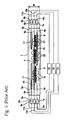
- coil-shaped filaments 4-6 are disposed together within a straight-tube type light-emitting tube 1 in a sequence extending in the tube axis direction of the light-emitting tube 1, wherein both ends are sealed airtight by hermetically sealed parts 2a. 2b.
- Internal leads 4a, 4b, 5a, 5b, 6a, 6b for supplying electrical current are connected respectively to both ends of the filaments 4, 5, 6.
- the internal leads for the filaments described above extend to the hermetically sealed parts on both ends respectively, and are separately connected electrically to external leads via sheets of metal foil.
- the internal leads 4a, 5a, 6a at one end of the filaments 4, 5, 6, are electrically connected to external leads 10a, 11a, 12a at one end via metal foils 7a, 8a, 9a on the hermetically sealed part 2a.
- the internal leads 4b, 5b, 6b at the other end are electrically connected to external leads 10b, 11b, 12b at the other end via metal foils 7b, 8b, and 9b on the hermetically sealed part 2b.
- each of the filaments 4, 5, and 6 can be supplied with electric current separately by being connected to separate electric current supply devices 13, 14, 15 via the external leads 10a, 10b, 11a, 11b, 12a, 12b.
- Insulating tubes 16, 17, 18 are fitted onto the internal leads 4b, 5a, 5b, 6a of the filaments 4, 5, 6, disposed at locations opposite from the filaments 4, 5, 6.
- circular anchors 19, 20, and 21 are disposed at locations between the inner wall of the light-emitting tube 1 and the insulating tubes 16, 17, 18 spaced in the tube axis direction of the light-emitting tube 1.
- the filaments 4, 5, 6 are each supported by 2 anchors, for example, without making contact with the light-emitting tube 1.
- the metal foil on the hermetically sealed parts at both ends has a parallel structure, with electric current supplied separately to each of the adjacent sheets of metal foil 7a, 8a, and 9a. Accordingly, a prescribed gap is required between the respective metal foil sheets in order to prevent electric discharge.
- the dimension W increases in the perpendicular direction (width direction) relative to the axis direction of the light-emitting tube with the hermetically sealed parts 2a, 2b, and in the case of a heating device in which a plurality of filament lamps is disposed in parallel, the overall size of the device increases, which is problematic.
- the dimension of the space between the lamps is limited by the width dimension of the hermetically sealed parts, making it impossible to dispose lamps in high density, which is problematic.
- the number of filaments within a single filament lamp needs to be increased in order to improve the separate controllability.
- the number of sheets of metal foil must also be increased in proportion, rendering the problems noted above still more serious.
- Fig. 1 shows a lamp in accordance with a first embodiment of a filament lamp according to the present invention.
- Fig. 2 shows a hermetically sealed part arrangement in accordance with a second embodiment of a filament lamp according to the present invention.
- Fig. 3 shows a seal arrangement in accordance with a third embodiment of a filament lamp according to the present invention.
- Fig. 4 shows a seal arrangement in accordance with a fourth embodiment of a filament lamp according to the present invention.
- Fig. 5 shows a conventional lamp.
- the present invention seeks to provide a filament lamp in which the width direction dimension of the hermetically sealed parts does not increase, even if the number of filaments, or in other words, the number of metal foil sheets, increases.
- the present invention is characterized by having a plurality of coil-shaped filaments disposed together in sequence in the tube axis direction of a light-emitting tube respectively in the interior of a light-emitting tube having hermetically sealed parts formed at the ends, with a pair of internal leads connected to the ends of each filament and the internal leads being electrically connected to external leads respectively via a plurality of sheets of metal foil; wherein some of the plurality of sheets of metal foil are disposed in staggered relation to the tube axis direction of the light-emitting tube to form a gap at the edges of the metal foil with respect to the other sheets of metal foil, and are disposed staggered in a direction perpendicular to the tube axis.
- the filament lamp according to the present invention confers the benefit of reducing the dimension in the direction perpendicular to the axis direction of the light-emitting tube with hermetically sealed parts (the width direction) by disposing the metal foils embedded in the hermetically sealed parts in a staggered manner, with some of the sheets of metal foil disposed in the tube axis direction of the light-emitting tube in relation to other metal foil, and others disposed in a direction perpendicular to the tube axis direction (the width direction).
- the metal foils embedded in the hermetically sealed parts in a staggered manner, with some of the sheets of metal foil disposed in the tube axis direction of the light-emitting tube in relation to other metal foil, and others disposed in a direction perpendicular to the tube axis direction (the width direction).
- Fig. 1 some of the sheets of metal foil attached to the internal leads of the filaments are disposed staggered in the tube axis direction of the light-emitting tube in relation to other metal foils, and some are disposed staggered in the direction perpendicular to the tube axis (the width direction).
- the metal foil 26a to which the internal lead 6a of filament 6 is attached is disposed staggered in the tube axis direction in relation to the metal foil 24a, to which is attached the internal lead 4a of filament 4, and relative to the metal foil 25a, to which is attached the internal lead 5a of filament 5, forming a gap L between the ends of the metal foils.
- these metal foils 24a, 25a, 26a are also disposed mutually staggered in a direction perpendicular to the tube axis. In other words, the foils are disposed in a zig-zag arrangement.
- the metal foils 24b, 25b, 26b in the hermetically sealed part 2b on the opposite end are disposed similarly.
- the need to create a gap in the width direction between the directly adjacent metal foil 24a and metal foil 26a, and between metal foil 26a and metal foil 25a is eliminated, whereas there was a need to create a prescribed gap in the perpendicular direction to the tube axis for the group of metal foils 7a, 8a, 9a for conventional arrangement shown in Fig. 5 .
- the dimension W in the width direction (the direction perpendicular to the tube axis) of the hermetically sealed parts 2a and 2b can be reduced.
- the metal foils 24a, 25a are disposed at the lamp end of the hermetically sealed part 2a, while the metal foil 26a is disposed in the direction of the light-emitting tube 1.
- the metal foil 26a may be disposed at the lamp end, and the metal foils 24a and 25a disposed toward the light-emitting tube 1, i.e., the opposite of the configuration of Fig. 1 .
- Figs. 1 & 2 an example was presented of three sheets of metal foil, or in other words, of three filaments.
- the present invention is not limited to this configuration. A case of four or more filaments is acceptable.
- Fig. 3 shows an example of four filaments, or in other words, having four sheets of metal foil.
- the metal foils 24a, 25a are disposed at the lamp ends, while the other two sheets, metal foils 26a, 27a are disposed staggered in the tube axis direction in relation to the others, and staggered in the direction perpendicular to the tube axis, forming a zig-zag configuration.
- Figs. 1-3 show an example of employing a pinch seal, but the same configuration can be adopted in a case in which a shrink seal is employed.
- Fig. 4 shows an example of this case.
- a detailed configuration of a shrink seal in a multi-filament lamp is described in commonly-owned U.S. Patent Application 2007/120454 .
- the staggering of the disposition of the metal foils 24a, 25a, 26a in the perpendicular direction to the tube axis in this case becomes a staggering in the circular direction of the hermetically sealed part 2a.
- Figs. 2-4 show only the hermetically sealed part 2a on one end.
- the hermetically sealed part 2b on the other end has the same metal foil disposition structure, of course.
- the dimension W in the perpendicular direction to the tube axis for the hermetically sealed part can be reduced, thus avoiding enlargement of the overall device incorporating the lamp and making possible parallel disposition of a plurality of lamps in high density.
Landscapes
- Life Sciences & Earth Sciences (AREA)
- Health & Medical Sciences (AREA)
- Veterinary Medicine (AREA)
- General Health & Medical Sciences (AREA)
- Environmental Sciences (AREA)
- Engineering & Computer Science (AREA)
- Zoology (AREA)
- Public Health (AREA)
- Animal Behavior & Ethology (AREA)
- Heart & Thoracic Surgery (AREA)
- Hematology (AREA)
- Biomedical Technology (AREA)
- Wood Science & Technology (AREA)
- Anesthesiology (AREA)
- Birds (AREA)
- Animal Husbandry (AREA)
- Biodiversity & Conservation Biology (AREA)
- Vascular Medicine (AREA)
- Resistance Heating (AREA)
- Non-Portable Lighting Devices Or Systems Thereof (AREA)
- Vessels And Coating Films For Discharge Lamps (AREA)
Applications Claiming Priority (1)
| Application Number | Priority Date | Filing Date | Title |
|---|---|---|---|
| JP2008090174A JP4670886B2 (ja) | 2008-03-31 | 2008-03-31 | フィラメントランプ |
Publications (2)
| Publication Number | Publication Date |
|---|---|
| EP2107596A2 true EP2107596A2 (de) | 2009-10-07 |
| EP2107596A3 EP2107596A3 (de) | 2010-08-04 |
Family
ID=40886561
Family Applications (1)
| Application Number | Title | Priority Date | Filing Date |
|---|---|---|---|
| EP09004281A Withdrawn EP2107596A3 (de) | 2008-03-31 | 2009-03-25 | Glühlampe |
Country Status (6)
| Country | Link |
|---|---|
| US (1) | US20090243461A1 (de) |
| EP (1) | EP2107596A3 (de) |
| JP (1) | JP4670886B2 (de) |
| KR (1) | KR101057302B1 (de) |
| CN (1) | CN101552180A (de) |
| TW (1) | TW200941543A (de) |
Families Citing this family (2)
| Publication number | Priority date | Publication date | Assignee | Title |
|---|---|---|---|---|
| JP5315833B2 (ja) * | 2008-07-28 | 2013-10-16 | ウシオ電機株式会社 | フィラメントランプ |
| KR20210095059A (ko) * | 2020-01-21 | 2021-07-30 | 에이에스엠 아이피 홀딩 비.브이. | 불균일한 열 출력의 필라멘트 램프를 갖는 반도체 처리 챔버 |
Citations (4)
| Publication number | Priority date | Publication date | Assignee | Title |
|---|---|---|---|---|
| JPH0737833A (ja) | 1993-07-22 | 1995-02-07 | Dainippon Screen Mfg Co Ltd | 基板の光照射式熱処理装置 |
| JP2002203804A (ja) | 2000-12-28 | 2002-07-19 | Tokyo Electron Ltd | 加熱装置、当該加熱装置を有する熱処理装置、及び、熱処理制御方法 |
| JP2006279008A (ja) | 2005-03-02 | 2006-10-12 | Ushio Inc | ヒータ及びヒータを備えた加熱装置 |
| US20070120454A1 (en) | 2005-11-30 | 2007-05-31 | Ushiodenki Kabushiki Kaisha | Filament lamp |
Family Cites Families (4)
| Publication number | Priority date | Publication date | Assignee | Title |
|---|---|---|---|---|
| JPS5637268U (de) * | 1979-08-23 | 1981-04-09 | ||
| EP1623447A2 (de) * | 2003-04-10 | 2006-02-08 | Koninklijke Philips Electronics N.V. | Lampenbaugruppe |
| WO2006000971A2 (en) * | 2004-06-24 | 2006-01-05 | Koninklijke Philips Electronics N.V. | Electric lamp |
| JP2007149614A (ja) * | 2005-11-30 | 2007-06-14 | Ushio Inc | フィラメントランプ及びフィラメントランプを備えた光照射式加熱処理装置 |
-
2008
- 2008-03-31 JP JP2008090174A patent/JP4670886B2/ja not_active Expired - Fee Related
-
2009
- 2009-01-30 KR KR1020090007358A patent/KR101057302B1/ko not_active Expired - Fee Related
- 2009-02-09 TW TW098104056A patent/TW200941543A/zh not_active IP Right Cessation
- 2009-03-12 CN CNA2009101265564A patent/CN101552180A/zh active Pending
- 2009-03-25 EP EP09004281A patent/EP2107596A3/de not_active Withdrawn
- 2009-03-25 US US12/410,633 patent/US20090243461A1/en not_active Abandoned
Patent Citations (4)
| Publication number | Priority date | Publication date | Assignee | Title |
|---|---|---|---|---|
| JPH0737833A (ja) | 1993-07-22 | 1995-02-07 | Dainippon Screen Mfg Co Ltd | 基板の光照射式熱処理装置 |
| JP2002203804A (ja) | 2000-12-28 | 2002-07-19 | Tokyo Electron Ltd | 加熱装置、当該加熱装置を有する熱処理装置、及び、熱処理制御方法 |
| JP2006279008A (ja) | 2005-03-02 | 2006-10-12 | Ushio Inc | ヒータ及びヒータを備えた加熱装置 |
| US20070120454A1 (en) | 2005-11-30 | 2007-05-31 | Ushiodenki Kabushiki Kaisha | Filament lamp |
Also Published As
| Publication number | Publication date |
|---|---|
| KR20090104644A (ko) | 2009-10-06 |
| US20090243461A1 (en) | 2009-10-01 |
| TWI344169B (de) | 2011-06-21 |
| TW200941543A (en) | 2009-10-01 |
| CN101552180A (zh) | 2009-10-07 |
| JP2009245720A (ja) | 2009-10-22 |
| EP2107596A3 (de) | 2010-08-04 |
| KR101057302B1 (ko) | 2011-08-16 |
| JP4670886B2 (ja) | 2011-04-13 |
Similar Documents
| Publication | Publication Date | Title |
|---|---|---|
| EP1699071B1 (de) | Heizelement und Heizvorrichtung mit Heizelementen | |
| JP4893474B2 (ja) | フィラメントランプおよび光照射式加熱処理装置 | |
| EP1918976B1 (de) | Glühlampe und lichtausstrahlende Wärmebehandlungsvorrichtung | |
| JP4935417B2 (ja) | 光照射式加熱処理装置 | |
| US8288932B2 (en) | Filament lamp | |
| JP2011103476A (ja) | ヒータランプを備えた加熱装置 | |
| EP2105948B1 (de) | Glühlampe | |
| EP2107596A2 (de) | Glühlampe | |
| US8072128B2 (en) | Filament lamp | |
| JP5304091B2 (ja) | フィラメントランプ | |
| KR101103180B1 (ko) | 필라멘트 램프 | |
| JP2010033858A (ja) | フィラメントランプ | |
| JP2009245721A (ja) | フィラメントランプ |
Legal Events
| Date | Code | Title | Description |
|---|---|---|---|
| PUAI | Public reference made under article 153(3) epc to a published international application that has entered the european phase |
Free format text: ORIGINAL CODE: 0009012 |
|
| AK | Designated contracting states |
Kind code of ref document: A2 Designated state(s): AT BE BG CH CY CZ DE DK EE ES FI FR GB GR HR HU IE IS IT LI LT LU LV MC MK MT NL NO PL PT RO SE SI SK TR |
|
| AX | Request for extension of the european patent |
Extension state: AL BA RS |
|
| PUAL | Search report despatched |
Free format text: ORIGINAL CODE: 0009013 |
|
| AK | Designated contracting states |
Kind code of ref document: A3 Designated state(s): AT BE BG CH CY CZ DE DK EE ES FI FR GB GR HR HU IE IS IT LI LT LU LV MC MK MT NL NO PL PT RO SE SI SK TR |
|
| AX | Request for extension of the european patent |
Extension state: AL BA RS |
|
| RIC1 | Information provided on ipc code assigned before grant |
Ipc: H01K 1/38 20060101ALI20100630BHEP Ipc: H01K 7/00 20060101ALI20100630BHEP Ipc: H01K 9/08 20060101AFI20100630BHEP |
|
| AKY | No designation fees paid | ||
| STAA | Information on the status of an ep patent application or granted ep patent |
Free format text: STATUS: THE APPLICATION IS DEEMED TO BE WITHDRAWN |
|
| 18D | Application deemed to be withdrawn |
Effective date: 20110205 |