EP2108400A1 - Herzrhythmussteuerungssystem mit regelbaren Austasteschwellenwert zwischen übersprechenden Herzkammersignalen - Google Patents
Herzrhythmussteuerungssystem mit regelbaren Austasteschwellenwert zwischen übersprechenden Herzkammersignalen Download PDFInfo
- Publication number
- EP2108400A1 EP2108400A1 EP09075337A EP09075337A EP2108400A1 EP 2108400 A1 EP2108400 A1 EP 2108400A1 EP 09075337 A EP09075337 A EP 09075337A EP 09075337 A EP09075337 A EP 09075337A EP 2108400 A1 EP2108400 A1 EP 2108400A1
- Authority
- EP
- European Patent Office
- Prior art keywords
- chamber
- sensing threshold
- atrial
- ventricular
- peak value
- Prior art date
- Legal status (The legal status is an assumption and is not a legal conclusion. Google has not performed a legal analysis and makes no representation as to the accuracy of the status listed.)
- Withdrawn
Links
- 230000000747 cardiac effect Effects 0.000 title claims abstract description 61
- 230000033764 rhythmic process Effects 0.000 title claims abstract description 60
- 230000001746 atrial effect Effects 0.000 claims abstract description 162
- 230000002861 ventricular Effects 0.000 claims abstract description 108
- 230000004044 response Effects 0.000 claims abstract description 62
- 230000001965 increasing effect Effects 0.000 claims abstract description 57
- 238000007726 management method Methods 0.000 claims abstract description 52
- 230000004213 regulation of atrial cardiomyocyte membrane depolarization Effects 0.000 claims abstract description 46
- 230000034225 regulation of ventricular cardiomyocyte membrane depolarization Effects 0.000 claims abstract description 35
- 230000000694 effects Effects 0.000 claims description 97
- 230000028161 membrane depolarization Effects 0.000 claims description 75
- 230000003247 decreasing effect Effects 0.000 claims description 67
- 238000000034 method Methods 0.000 claims description 50
- WABPQHHGFIMREM-UHFFFAOYSA-N lead(0) Chemical compound [Pb] WABPQHHGFIMREM-UHFFFAOYSA-N 0.000 claims description 44
- 230000007423 decrease Effects 0.000 claims description 37
- 210000005240 left ventricle Anatomy 0.000 description 47
- 210000005245 right atrium Anatomy 0.000 description 47
- 210000005241 right ventricle Anatomy 0.000 description 46
- 210000005246 left atrium Anatomy 0.000 description 42
- 238000010586 diagram Methods 0.000 description 18
- 210000002837 heart atrium Anatomy 0.000 description 18
- 210000005242 cardiac chamber Anatomy 0.000 description 17
- 206010003119 arrhythmia Diseases 0.000 description 10
- 238000001514 detection method Methods 0.000 description 9
- 230000008878 coupling Effects 0.000 description 8
- 238000010168 coupling process Methods 0.000 description 8
- 238000005859 coupling reaction Methods 0.000 description 8
- 102100026827 Protein associated with UVRAG as autophagy enhancer Human genes 0.000 description 5
- 101710102978 Protein associated with UVRAG as autophagy enhancer Proteins 0.000 description 5
- 239000008280 blood Substances 0.000 description 5
- 210000004369 blood Anatomy 0.000 description 5
- 238000002560 therapeutic procedure Methods 0.000 description 5
- 230000006793 arrhythmia Effects 0.000 description 4
- 230000006870 function Effects 0.000 description 4
- 238000005086 pumping Methods 0.000 description 4
- 208000001871 Tachycardia Diseases 0.000 description 3
- 210000003748 coronary sinus Anatomy 0.000 description 3
- 206010007559 Cardiac failure congestive Diseases 0.000 description 2
- 206010019280 Heart failures Diseases 0.000 description 2
- 230000017531 blood circulation Effects 0.000 description 2
- 230000008602 contraction Effects 0.000 description 2
- 230000003292 diminished effect Effects 0.000 description 2
- 238000012377 drug delivery Methods 0.000 description 2
- 238000002651 drug therapy Methods 0.000 description 2
- 230000000763 evoking effect Effects 0.000 description 2
- 206010049447 Tachyarrhythmia Diseases 0.000 description 1
- 210000001015 abdomen Anatomy 0.000 description 1
- 230000009471 action Effects 0.000 description 1
- 230000002411 adverse Effects 0.000 description 1
- 210000004204 blood vessel Anatomy 0.000 description 1
- 208000006218 bradycardia Diseases 0.000 description 1
- 238000012512 characterization method Methods 0.000 description 1
- 210000003109 clavicle Anatomy 0.000 description 1
- 239000004020 conductor Substances 0.000 description 1
- 230000003111 delayed effect Effects 0.000 description 1
- 239000003814 drug Substances 0.000 description 1
- 229940079593 drug Drugs 0.000 description 1
- 230000009977 dual effect Effects 0.000 description 1
- 230000010247 heart contraction Effects 0.000 description 1
- 230000036039 immunity Effects 0.000 description 1
- 230000001788 irregular Effects 0.000 description 1
- 230000007246 mechanism Effects 0.000 description 1
- 238000012544 monitoring process Methods 0.000 description 1
- 210000003205 muscle Anatomy 0.000 description 1
- 230000036279 refractory period Effects 0.000 description 1
- 230000035945 sensitivity Effects 0.000 description 1
- 230000035939 shock Effects 0.000 description 1
- 230000001052 transient effect Effects 0.000 description 1
Images







Classifications
-
- A—HUMAN NECESSITIES
- A61—MEDICAL OR VETERINARY SCIENCE; HYGIENE
- A61N—ELECTROTHERAPY; MAGNETOTHERAPY; RADIATION THERAPY; ULTRASOUND THERAPY
- A61N1/00—Electrotherapy; Circuits therefor
- A61N1/18—Applying electric currents by contact electrodes
- A61N1/32—Applying electric currents by contact electrodes alternating or intermittent currents
- A61N1/36—Applying electric currents by contact electrodes alternating or intermittent currents for stimulation
- A61N1/362—Heart stimulators
- A61N1/37—Monitoring; Protecting
- A61N1/3702—Physiological parameters
- A61N1/3704—Circuits specially adapted therefor, e.g. for sensitivity control
-
- Y—GENERAL TAGGING OF NEW TECHNOLOGICAL DEVELOPMENTS; GENERAL TAGGING OF CROSS-SECTIONAL TECHNOLOGIES SPANNING OVER SEVERAL SECTIONS OF THE IPC; TECHNICAL SUBJECTS COVERED BY FORMER USPC CROSS-REFERENCE ART COLLECTIONS [XRACs] AND DIGESTS
- Y10—TECHNICAL SUBJECTS COVERED BY FORMER USPC
- Y10S—TECHNICAL SUBJECTS COVERED BY FORMER USPC CROSS-REFERENCE ART COLLECTIONS [XRACs] AND DIGESTS
- Y10S128/00—Surgery
- Y10S128/901—Suppression of noise in electric signal
Definitions
- This invention relates generally to cardiac rhythm management systems and particularly, but not by way of limitation, to a cardiac rhythm management system with cross-chamber Asoft blanking@ for sensing desired signals and reducing unwanted noise.
- cardiac arrhythmias When functioning properly, the human heart maintains its own intrinsic rhythm, and is capable of pumping adequate blood throughout the body's circulatory system. However, some people have irregular cardiac rhythms, referred to as cardiac arrhythmias. Such arrhythmias result in diminished blood circulation.
- One mode of treating cardiac arrhythmias is via drug therapy. Drugs are often effective at restoring normal heart rhythms. However, drug therapy is not always effective for treating arrhythmias of certain patients. For such patients, an alternative mode of treatment is needed.
- One such alternative mode of treatment includes the use of a cardiac rhythm management system. Such systems are often implanted in the patient and deliver therapy to the heart.
- Cardiac rhythm management systems include, among other things, pacemakers, or pacers.
- Pacers deliver timed sequences of low energy electrical stimuli, called pace pulses, to the heart. Heart contractions are initiated in response to such pace pulses. By properly timing the delivery of pace pulses, the heart can be induced to contract in proper rhythm, greatly improving its efficiency as a pump.
- Pacers are often used to treat patients with bradyarrhythmias, that is, hearts that beat too slowly, or irregularly.
- Cardiac rhythm management systems also include cardioverters or defibrillators that are capable of delivering higher energy electrical stimuli to the heart.
- a defibrillator is capable of delivering an high energy electrical stimulus that is sometimes referred to as a countershock. The countershock interrupts the tachyarrhythmia, allowing the heart to reestablish a normal rhythm for the efficient pumping of blood.
- cardiac rhythm management systems also include, among other things, pacer/defibrillators that combine the functions of pacers and defibrillators, drug delivery devices, and any other systems or devices for diagnosing or treating cardiac arrhythmias.
- Modem cardiac rhythm management systems are also typically capable of sensing intrinsic electrical heart activity signals.
- These electrical heart activity signals include cardiac depolarizations that are autonomously produced by the heart. The depolarizations initiate the contractions of the muscle tissue of the heart. These contractions, in turn, pump blood through the circulatory system.
- the pulse generator includes a power source, such as a battery, as well as sensing, therapy, and timing circuits.
- the pulse generator is coupled to the heart via endocardial leadwires.
- Such leadwires are typically routed from the pulse generator to the heart through blood vessels. Electrodes are located at the terminal end of these leadwires, distal from the pulse generator. The electrodes are typically positioned in the right atrium and right ventricle of the heart.
- Pacing pulses are delivered to the heart via the electrodes. Moreover, the intrinsic electrical heart activity signals are received at the electrodes and communicated to the pulse generator via the leadwires. At the pulse generator, atrial and ventricular sensing circuits detect atrial and ventricular depolarizations in the respective atrial and ventricular electrical heart activity signals. The pulse generator adjusts the therapy delivered according to the sensed atrial and ventricular depolarization information. In one mode of operation, for example, the pulse generator withholds delivery of a scheduled pacing pulse when it detects that the heart is already contracting as the result of an intrinsic cardiac depolarization.
- Sensing intrinsic heart activity signals in each of the atrium and ventricle is complicated by the fact that an electrode placed in one chamber may receive not only intrinsic heart activity signals from that chamber of the heart, but the electrode may also receive unwanted Across-chamber@ intrinsic heart activity signals, that is, far-field noise signals resulting from depolarizations in the other chamber of the heart. For example, this is particularly problematic in using the atrial electrode to detect atrial depolarizations. Because ventricular depolarizations typically have a larger signal amplitude than atrial depolarizations, the atrial electrode is likely to detect the ventricular depolarization as well as the atrial depolarization.
- At least two problems are caused by cross-chamber sensing of heart activity signals originating in a heart chamber other than that in which the electrode is located.
- the pulse generator may erroneously recognize the cross-chamber ventricular depolarization as being an atrial depolarization.
- the pulse generator may improperly withhold delivery of a pace pulse to the atrium because it erroneously thought the atrium was already contracting.
- the occurrence of ventricular depolarization may obscure detection of an atrial depolarization that occurs at about the same time as the ventricular depolarization.
- cross-chamber sensing of a ventricular depolarization by the atrial electrode results in a noisy signal at the atrial electrode that makes it more difficult for the atrial sensing circuit to detect an actual atrial depolarization.
- cross-chamber sensing of an atrial depolarization by the ventricular electrode makes it more difficult for the ventricular sensing circuit to detect an actual ventricular depolarization.
- cross-chamber blanking One technique for dealing with cross-chamber sensing of unwanted far-field signals is referred to as cross-chamber blanking.
- a ventricular event i.e., a sensed ventricular depolarization or a delivered ventricular pace pulse
- a lengthy time period referred to as a blanking or refractory period.
- electrical heart activity signals received at the atrial electrode are simply ignored.
- the occurrence of an atrial event i.e., a sensed atrial depolarization or a delivered atrial pace pulse
- cross-chamber blanking technique requires the use of relatively long blanking periods. For example, it is not uncommon to ignore signals at the atrial electrode for a blanking period of approximately between 80 - 90 milliseconds after the occurrence of a ventricular event. However, in patients having cardiac arrhythmias, and particularly patients with tachyarrhythmias, it is quite common to lose synchronization between atrial and ventricular depolarizations. For example, an actual atrial depolarization may occur during the 80 - 90 millisecond blanking period that follows a ventricular event. However, such an atrial depolarization would be improperly ignored according to the cross-chamber blanking technique described above.
- the pulse generator may improperly issue a pace pulse to the atrium.
- the pulse generator may operate to decrease the pumping efficiency of the heart.
- a cardiac arrhythmia could be initiated by multiple occurrences of improperly timed pace pulses.
- the detection of a cardiac arrhythmia could be delayed by multiple occurrences of atrial depolarizations during blanking periods.
- ventricular therapy may also be adversely affected by cross-chamber sensing of electrical signals from the atrium.
- the present cardiac rhythm management system provides, among other things, cross-chamber Asoft blanking.@
- the system allows sensing of desired electrical heart activity signals from an electrode located in a first chamber of the heart, while reducing unwanted noise signals originating in a second chamber of the heart.
- unwanted noise signals include, among other things, intrinsic cardiac depolarizations associated with the second chamber of the heart as well as pace pulses delivered to the second chamber of the heart.
- the soft-blanking advantageously minimizes the erroneous sensing of second-chamber depolarizations as first-chamber depolarizations, which could result in a pace pulse being inappropriately withheld from the first chamber when it should have been delivered.
- This document describes, among other things, a cardiac rhythm management system with cross-chamber Asoft blanking.@ The system allows sensing of desired electrical heart activity signals from an electrode located in a first chamber of the heart, while reducing unwanted noise signals originating in a second chamber of the heart.
- unwanted noise signals include, among other things, intrinsic cardiac depolarizations associated with the second chamber of the heart as well as pace pulses delivered to the second chamber of the heart.
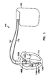
- FIG. 1 is a generalized schematic diagram illustrating generally, by way of example, but not by way of limitation, one embodiment of a portion of a cardiac rhythm management system 100.
- Various embodiments of system 100 include external or implantable pacers, cardioverters, defibrillators, drug delivery systems, cardiac signal monitoring or diagnostic systems, any combination of the foregoing, or any other system using or maintaining cardiac rhythms.
- cardiac rhythm management system 100 includes a cardiac rhythm management device 105 coupled to heart 110 via a first chamber leadwire, such as atrial leadwire 115, and a second chamber leadwire, such as ventricular leadwire 120.
- atrial leadwire 115 includes one or more atrial electrodes 125, such as atrial tip electrode 125A and atrial ring electrode 125B, each of which is disposed in a right atrium 130 chamber of heart 110.
- Ventricular leadwire 120 includes one or more ventricular electrodes 135, such as ventricular tip electrode 135A and ventricular ring electrode 135B, each of which is disposed in a right ventricle 140 chamber of heart 110 .
- Atrial leadwire 115 and ventricular leadwire 120 may also include additional electrodes, such as defibrillation electrodes 145A-B which, in this example, are located on ventricular leadwire 120 for delivering an electrical defibrillation countershock to heart 110.
- leadwires 115 and 120 each include multiple conductors that are insulated from each other for providing independent connections between each electrode and cardiac rhythm management device 105.
- atrial tip electrode 125A and ventricular tip electrode 135A are each secured in place to heart 110, such as by a corkscrew, a barb, or similar mechanism.
- cardiac rhythm management device 105 includes a hermetically sealed casing, a portion of which provides a conductive electrode that operates in conjunction with at least one of the electrodes disposed in heart 110 for delivering pacing and/or defibrillation pulses and/or sensing electrical heart activity signals.
- FIG. 2 is a block diagram illustrating generally, by way of example, but not by way of limitation, one embodiment of a portion of cardiac rhythm management device 105.
- This embodiment provides defibrillation and dual-chamber pacing, i.e., a pacer/defibrillator.
- other embodiments include a dual chamber pacer without defibrillation capability.
- cardiac rhythm management device 105 includes first chamber input/output terminals, such as atrial input/output terminals 200A for receiving atrial leadwire 115.
- Cardiac rhythm management device 105 also includes second chamber input/output terminals, such as ventricular input/output terminals 200B for receiving ventricular leadwire 120.
- Cardiac rhythm management device 105 is coupled to atrium 130 via atrial input/output terminals 200A and atrial leadwire 115 for delivering timed pacing pulses from pace pulse circuit 205A to atrium 130, and also for receiving, at filter circuit 210A, an electrical atrial heart activity signal from atrium 130.
- cardiac rhythm management device 105 is coupled to ventricle 140 of heart 110 via ventricular input/output terminals 200B and ventricular leadwire 120, for delivering timed pacing pulses from pace pulse circuit 205B and/or defibrillation countershocks from shock pulse circuit 212 to ventricle 140 and also for receiving, at filter circuit 210B, an electrical ventricular heart activity signal from ventricle 140.
- Filters 210 filter the respective electrical heart activity signals.
- filters 210 also each include an after-potential removal circuit for removing, from such heart activity signals, after-potentials that are created by pacing pulses or defibrillation countershocks.
- an after-potential removal circuit is described in Haefner et al. U.S. Patent Number 5,690,683 , which is assigned to the assignee of the present application, and which is incorporated herein by reference in its entirety, including its portions relating to after-potential removal systems, circuits, and methods.
- Atrial automatic gain control (AGC) circuit 215A amplifies, filters, and digitizes the filtered analog atrial heart activity signal received from atrial filter 210A. Atrial gain control circuit 220A automatically adjusts the gain of atrial AGC 215A. In one embodiment, atrial gain control circuit 220A and atrial AGC 215A form a peak adjustment circuit for adjusting the gain of atrial heart activity signals (and resulting peak amplitudes of atrial depolarizations) based on one or more prior atrial depolarizations. The digitized atrial heart activity signal that is output by atrial AGC 215A is received by an atrial detector 225A.
- Atrial detector 225A detects atrial events indicated by (1) the digitized heart activity signal or (2) from signals received from processor 230. For example, atrial detector 225A detects atrial depolarizations, also referred to as P-waves. The atrial depolarizations are detected by comparing the digitized atrial heart activity signal received from atrial AGC 215A to a value of an atrial sensing threshold. The atrial sensing threshold is provided to atrial detector 225A from a threshold controller, such as atrial template generation circuit 235A. In one embodiment, the atrial sensing threshold is time-varying, as discussed below. In one embodiment, atrial detector 225A also detects other atrial events, such as atrial pace pulses delivered from cardiac rhythm management device 105 to atrium 130.
- atrial depolarizations also referred to as P-waves. The atrial depolarizations are detected by comparing the digitized atrial heart activity signal received from atrial AGC 215A to a value of an atrial sensing threshold.
- the atrial pace pulses are detected either from (1) the digitized atrial heart activity signal output from atrial AGC 215A or (2) from a control signal received from processor 230 indicating that an atrial pace pulse was delivered by cardiac rhythm management device 105.
- Another possible example of an atrial event detected by atrial detector 225A is a defibrillation countershock delivered to by system 100 to heart 110.
- ventricular automatic gain control (AGC) circuit 215B amplifies, filters, and digitizes the filtered analog ventricular heart activity signal received from ventricular filter 210B.
- Ventricular gain control circuit 220B automatically adjusts the gain of ventricular AGC 215B.
- ventricular gain control circuit 220B and ventricular AGC 215B form a peak adjustment circuit for adjusting a gain (and resulting peak amplitudes of ventricular depolarizations) of ventricular heart activity signals based on one or more prior ventricular depolarizations.
- the digitized ventricular heart activity signal that is output by AGC 215B is received by a ventricular detector 225B.
- Ventricular detector 225B detects ventricular events indicated by (1) the digitized heart activity signal or (2) from signals received from processor 230. For example, ventricular detector 225B detects ventricular depolarizations, also referred to as R-waves. The ventricular depolarizations are detected by comparing the digitized ventricular heart activity signal received from ventricular AGC 215B to a value of a ventricular sensing threshold provided by a threshold controller, such as template generation circuit 235B. In one embodiment, the ventricular sensing threshold is time-varying, as discussed below. In one embodiment, ventricular detector 225B also detects other ventricular events, such as ventricular pace pulses delivered from cardiac rhythm management device 105 to ventricle 140.
- ventricular depolarizations also referred to as R-waves. The ventricular depolarizations are detected by comparing the digitized ventricular heart activity signal received from ventricular AGC 215B to a value of a ventricular sensing threshold provided by a threshold controller, such as template generation circuit 235B. In one
- the ventricular pace pulses are detected either from (1) the digitized ventricular heart activity signal output from ventricular AGC 215B or (2) from a control signal received from processor 230 indicating that a ventricular pace pulse was delivered by cardiac rhythm management device 105.
- a ventricular event detected by ventricular detector 225B is a defibrillation countershock delivered by system 100 to heart 110.
- Processor 230 analyzes the detected atrial and ventricular events for characterizing and treating various arrhythmia conditions of heart 110.
- Processor 230 is capable of storing, in internal or external memory, data regarding the occurrence of atrial and ventricular events for use in arrhythmia characterization and treatment algorithms.
- processor 230 uses a state machine 232 that places various circuits of cardiac rhythm management device 105 in desired logical states based on conditions determined by algorithms performed by processor 230.
- Figure 3 is a flow chart illustrating generally, by way of example, but not by way of limitation, one embodiment of the operation of system 100 to provide cross-chamber Asoft blanking.@ The soft blanking allows sensing of desired electrical heart activity signals from an electrode located in a first chamber of the heart while reducing unwanted noise signals originating in a second chamber of the heart.
- a first chamber event is detected at step 300.
- the first chamber event is an atrial pace pulse or an atrial depolarization indicated by the atrial heart activity signal.
- cardiac rhythm management device 105 itself provides the atrial pace pulse
- detection of the atrial pace pulse includes, in one embodiment, receiving a control signal, such as from processor 230, indicating that the atrial pace pulse was issued by cardiac rhythm management device 105.
- a first chamber sensing threshold is increased to a first peak value.
- the atrial sensing threshold provides, in one embodiment, a time varying value to which the filtered atrial heart activity signal is compared. If the filtered atrial heart activity signal exceeds the value of the atrial sensing threshold, then atrial detector 225A declares that an atrial depolarization has been detected. By increasing the atrial sensing threshold after the detection of an atrial depolarization, atrial detector 225A is made less sensitive to subsequent variations in the atrial heart activity signal. As a result of increasing the atrial sensing threshold at step 305, larger amplitude variations in the atrial heart activity signal are required for being deemed atrial depolarizations.
- the first chamber sensing threshold is decreased toward a first steady-state value.
- this includes reducing the atrial sensing threshold in a quantized approximation of a decaying exponential function, such as described in Haefner et al. U.S. Patent Number 5,620,466 , Haefner et al. U.S. Patent Number 5,658,317 , and Haefner et al. U.S. Patent Number 5,662,688 , which were above incorporated herein by reference.
- a decaying exponential function such as described in Haefner et al. U.S. Patent Number 5,620,466 , Haefner et al. U.S. Patent Number 5,658,317 , and Haefner et al. U.S. Patent Number 5,662,688 , which were above incorporated herein by reference.
- the atrial sensing threshold is decreased at step 310A-B, smaller amplitude variations in the atrial heart activity signal will be recognized as being atrial de
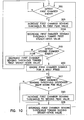
- step 315 if a second chamber event is not detected, system 100 continues to decrease the first chamber sensing threshold toward the first steady-state value at step 310B, then returning to step 300 after the first chamber sensing threshold has reached the first steady-state value. If, however, a second chamber event is detected at step 315, then at step 317 system 100 determines whether the first chamber sensing threshold has decreased below a predetermined comparison value.
- step 317 if the first chamber sensing threshold has decreased below the predetermined comparison value, then the first chamber sensing threshold is again increased, at step 320, such as to a second peak value, and then decreased toward a second steady-state value at step 325.
- the first chamber sensing threshold is decreased toward the second steady-state value at step 325 without increasing the first chamber sensing threshold at step 320.
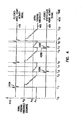
- FIG. 4 is a signal flow diagram illustrating generally, by way of example, but not by way of limitation, one embodiment of the operation of system 100 such as, for example, in the sequence of steps described with respect to the flow chart of Figure 3 .
- time is illustrated generally on horizontal axis 400
- the atrial sensing threshold 405 is a digital signal measured in digital Acounts@ and referenced to vertical axis 410.
- atrial sensing threshold 405 is an 8-bit digital Aword@ with values ranging between 0 counts and 127 counts.
- Figure 4 also illustrates a filtered atrial heart activity signal 415 output by atrial AGC 215A, and a filtered ventricular heart activity signal 420 output by ventricular AGC 215B.
- atrial heart activity signal 415 and ventricular heart activity signal 420 are not referenced to vertical axis 410.
- At time t 0 atrial sensing threshold 405 is at a first steady-state value A 1 which, in this example, is equal to approximately 15 counts.
- the atrial heart activity signal 415 includes an atrial depolarization 415A which, in this example, is an intrinsic atrial depolarization.
- An intrinsic depolarization is a depolarization that is produced by the heart itself, that is, without being initiated by a pace pulse delivered by system 100.
- Atrial detector 225A compares the amplitude of intrinsic atrial depolarization 415A to the existing value of atrial sensing threshold 405 which, at time t 1, is at the first steady-state value A 1 . In this example, because the amplitude of the atrial depolarization exceeds A 1 , atrial sensing threshold 405 is increased, at time t 1 , to a first peak value A 2 .
- the first peak value A 2 of atrial sensing threshold 405 is approximately between 80 and 127 counts, and is adjusted automatically based on the amplitude of prior atrial depolarizations, such as described in Haefner et al. U.S. Patent No. 5,658,317 , which was above incorporated herein by reference.
- atrial sensing threshold 405 is decreased from first peak value A 2 toward first steady-state value A 1 which, in this particular example, atrial sensing threshold 405 attains at time t 2 .
- system 100 decreases atrial sensing threshold 405 in discrete steps as described in Haefner et al. U.S. Patent No. 5,658,317 , which was above incorporated herein by reference.
- ventricular heart activity signal 420 includes an intrinsic ventricular depolarization 420A that exceeds a ventricular sensing threshold.
- atrial sensing threshold 405 is increased to a second peak value A 3 .
- second peak value A 3 falls between first peak value A 2 and first steady-state value A 1 of atrial sensing threshold 405.
- second peak value A 3 is approximately equal to 3/8 of the first peak value A 2 (e.g., A 3 . 42 counts and A 2 . 112 counts).
- system 100 provides automatic gain control (AGC), which operates to maintain the first peak value A 2 between an AGC lower limit (e.g., 80 counts) and an AGC upper limit (e.g., 127 counts). Maintaining A 2 between the upper and lower AGC limits is based on the amplitude of previously-received atrial depolarizations. As a result, during certain transient conditions (e.g., at startup), A 2 may fall outside the upper and lower AGC limits. In one example, when A 2 falls below the AGC lower limit (e.g., 80 counts), system 100 establishes the second peak value A 3 at approximately 3/8 of the AGC lower limit (e.g., 3/8 of 80 counts).
- system 100 decreases atrial sensing threshold 405 toward a second steady-state value at time t 4 .
- the second steady-state value is approximately equivalent to the first steady state value A 1
- atrial sensing threshold 405 is decreased toward A 1 in discrete steps as described in Haefner et al. U.S. Patent No. 5,658,317 , which was above incorporated herein by reference.
- the second steady-state value is different from the first steady-state value A 1 .
- system 100 By increasing atrial sensing threshold 405, during a time period between t 3 and t 4 in response to ventricular depolarization 420A, system 100 effectively provides a cross-chamber soft-blanking function.
- the increased atrial sensing threshold 405 reduces the sensitivity of atrial detector 225A when ventricular detector 225B indicates a ventricular depolarization.
- the ventricular depolarization results in far-field noise that may be improperly sensed by atrial detector 225A if atrial sensing threshold 405 were not increased as described above.
- atrial heart activity signal 415 is not completely ignored during the time period between t 3 and t 4 . Instead, atrial detector 225A remains capable of detecting an atrial depolarization during the time period between t 3 and t 4 , provided that the atrial depolarization exceeds the value of atrial sensing threshold 405 during that time.
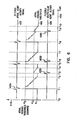
- FIG. 5 is a signal flow diagram that follows analogously from the description of Figure 4 , in which a ventricular sensing threshold 505 is increased and then decreased, during a time period between t 3 and t 4 , in response to atrial depolarization 415A.
- Figure 5 illustrates one example of carrying out the technique of Figure 3 where the first chamber is ventricle 140 and the second chamber is atrium 130.
- Figure 4 illustrated one example of carrying out the technique of Figure 3 where the first chamber was atrium 130 and the second chamber is ventricle 140.
- Figure 4 also illustrates cross-chamber soft blanking during a time period between t 7 and t 8 in response to a ventricular event that includes a ventricular pace pulse 420B that triggers a resulting ventricular depolarization 420C.
- system 100 issues the ventricular pace pulse 420B, it is not necessary to detect the evoked ventricular depolarization 420C before increasing the atrial sensing threshold 405 to A 3 .
- processor 230 issues a control signal to template generation circuit 235A when ventricular pace pulse 420B is issued. Based on this control signal representing the delivery of ventricular pace pulse 420B, the atrial sensing threshold 405 is increased to A 3 .
- Figure 5 also illustrates cross-chamber soft blanking during a time period between t 7 and t 8 in response to an atrial event that includes an atrial pace pulse 415B that triggers a resulting atrial depolarization 415C.
- atrial pace pulse 415B is a second chamber event that results in the increase in the ventricular sensing threshold 505.
- Figure 6 is a signal flow diagram, similar to Figure 4 , illustrating by way of example, but not by way of limitation one embodiment of the operation of system 100 as described with respect to Figure 3 .
- the signals of Figure 6 display similar characteristics to those of Figure 4 until t 6 , at which time intrinsic ventricular depolarization 420B occurs.
- Ventricular depolarization 420B is a second chamber event that is detected at step 315 of Figure 3 .
- the first chamber sensing threshold e.g., atrial sensing threshold 405 in Figure 6
- a predetermined comparison value which in this particular example is equal to second peak value A 3
- the atrial sensing threshold 405 is not increased because it still exceeds a predetermined comparison value that, in this example, is equal to second peak value A 3 . Instead, system 100 continues to decrease the atrial sensing threshold 405 toward a second steady-state value which, in this example, is equivalent to first steady-state value A 1 attained at time t 7 .
- intrinsic ventricular depolarization 420C is a second chamber event that is detected at step 315 of Figure 3 .
- the first chamber sensing threshold e.g., atrial sensing threshold 405 in Figure 6
- the first chamber sensing threshold is increased, such as described with respect to step 320 of Figure 3 .
- Atrial sensing threshold 405 is increased to a second peak value A 3 that, in this example, is approximately equal to the predetermined comparison value at step 317 of Figure 3 .
- the predetermined comparison value for triggering an increased atrial sensing threshold 405 need not necessarily be the same value of the atrial sensing threshold 405 as the second peak value A 3 to which the atrial sensing threshold 405 is increased.
- Figures 3 - 6 separately illustrate, among other things, the use of cross-chamber soft blanking in atrium 130, in response to ventricular pacing and intrinsic depolarization events, or in ventricle 140, in response to atrial pacing and intrinsic depolarization events.
- system 100 carries out cross-chamber soft blanking simultaneously in multiple chambers of heart 110.
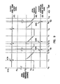
- FIG. 7 is a signal flow diagram illustrating generally, by way of example, but not by way of limitation, one embodiment of operating system 100 for cross-chamber soft blanking simultaneously in both atrium 130 and ventricle 140.
- atrial heart activity signal 415 includes an intrinsic atrial depolarization 415A, which triggers in increase in atrial sensing threshold 405 from A 1 to A 2 , from which atrial sensing threshold 405 subsequently begins to decrease back toward A 1 .
- Atrial depolarization 415A also triggers cross-chamber soft-blanking.
- ventricular sensing threshold 505 is below a predetermined comparison value (e.g., below V 3 )
- system 100 increases ventricular sensing threshold 505 from V 1 to V 3 , from which ventricular sensing threshold 505 subsequently begins to decrease back toward V 1 .
- ventricular heart activity signal 420 indicates an intrinsic ventricular depolarization 420A, which triggers an increase in ventricular sensing threshold 505 from V 1 to V 2 , from which ventricular sensing threshold 505 begins to decrease back toward V 1 .
- Ventricular depolarization 420A also triggers cross-chamber soft-blanking. Because, at time t 3 , atrial sensing threshold 405 is below a predetermined comparison value (e.g., below A 3 ), system 100 increases atrial sensing threshold 405 from A 1 to A 3 , from which atrial sensing threshold 405 begins to decrease back toward A 1 .
- At time t 5 atrial heart activity signal 415 indicates an intrinsic atrial depolarization 415B, which triggers an increase in atrial sensing threshold 405 from A 1 to A 2 , from which atrial sensing threshold 405 begins to decrease back toward A 1 .
- atrial depolarization 415B does not trigger a cross-chamber increase in ventricular sensing threshold 505 because, at time t 5 , ventricular sensing threshold 505 already exceeds a predetermined value (e.g., V 3 ).
- ventricular heart activity signal 420 indicates that a ventricular pace pulse 420B was delivered, evoking a resulting ventricular depolarization 420C.
- Ventricular pace pulse 420B triggers an increase in ventricular sensing threshold 505 from V 1 to V 2 , from which ventricular sensing threshold 505 begins to decrease back toward V 1 .
- Ventricular pace pulse 420B also triggers a cross-chamber soft-blanking. Because, at time t 8 , atrial sensing threshold 405 is below a predetermined comparison value (e.g., below A 3 ), system 100 increases atrial sensing threshold 405 from A 1 to A 3 , from which atrial sensing threshold 405 begins to decrease back toward A 1 .
- a predetermined comparison value e.g., below A 3
- At time t 10 atrial heart activity signal 415 indicates an intrinsic atrial depolarization 415C, which triggers an increase in atrial sensing threshold 405 from A 1 to A 2 , from which atrial sensing threshold 405 begins to decrease back toward A 1 .
- atrial depolarization 415C does not trigger a cross-chamber increase in ventricular sensing threshold 505 because, at time t 10 , ventricular sensing threshold 505 already exceeds a predetermined value (e.g., V 3 ).
- At time t 13 atrial heart activity signal 415 includes an intrinsic atrial depolarization 415D, which triggers in increase in atrial sensing threshold 405 from A 1 to A 2 , from which atrial sensing threshold 405 subsequently begins to decrease back toward A 1 .
- Atrial depolarization 415D also triggers a cross-chamber soft-blanking. Because, at time t 13 , ventricular sensing threshold 505 is below a predetermined comparison value (e.g., below V 3 ), system 100 increases ventricular sensing threshold 505 from V 1 to V 3 , from which ventricular sensing threshold 505 subsequently begins to decrease back toward V 1 .
- a predetermined comparison value e.g., below V 3
- FIG 7 illustrated, among other things, cross-chamber soft blanking being carried out simultaneously in two chambers of heart 110. It is understood, however, that such cross-chamber soft blanking can also be carried out simultaneously in more than two chambers of heart 110. Similarly, such soft blanking can be carried out in a single chamber of heart 110, as illustrated in Figures 3 - 6 , but based on cross-chamber signals received from more than one other chamber of heart 110. Moreover, even though the term heart chamber is used, it is understood that signals associated with a particular heart chamber may be obtained via an electrode that is not actually disposed in the heart chamber, but is instead disposed near enough to the heart chamber (e.g., an epicardial electrode) to acquire signals associated with that heart chamber.
- Figure 8 is a flow chart illustrating generally, by way of example, but not by way of limitation, another embodiment of operation of system 100. Steps 300, 305, 310A-B, 315, and 317 are as described with respect to Figure 3 . If system 100 detects a second chamber event, at step 315, and the first chamber sensing threshold has decreased below the second peak value, at step 317, then first chamber signals are ignored (Ablanked@ or Ahard-blanked@) for a short period of time (e.g., less than approximately between 5 - 15 milliseconds) at step 800. Next, the first chamber sensing threshold is increased (i.e., with respect to the steady-state value) to the third peak value at step 320.
- a short period of time e.g., less than approximately between 5 - 15 milliseconds
- system 100 continues to decrease the first chamber sensing threshold toward the second steady-state value, at step 325, without briefly ignoring the first chamber signals at step 800 and without first increasing the first chamber sensing threshold at step 320.
- Figure 9 is a signal flow diagram, illustrating generally, by way of example, but not by way of limitation one embodiment of operation of system 100 as described with respect to Figure 8 .
- the signals of Figure 9 display similar characteristics to those of Figure 6 until t 3A , at which time intrinsic ventricular depolarization 420A occurs. This triggers a cross-chamber blanking that includes ignoring signals received from atrium 130 for a brief period of time between t 3A and t 3B , such time being shorter than approximately between 5 - 15 milliseconds. In Figure 9 , this is represented by an infinite value, A 4 , of atrial sensing threshold 405.
- Atrial sensing threshold 405 increases (with respect to steady-state baseline value A 1 ) to A 3 , at time t 3B , and then decreased toward A 1 .
- a similar cross-chamber soft-blanking occurs between times t 9B and t 10 .
- At time t 6 intrinsic ventricular depolarization 420B occurs. However, at that time atrial sensing threshold 405 has not decreased below a predetermined value (e.g., A 3 ), so no cross-chamber blanking is performed.
- a predetermined value e.g., A 3
- the above-described embodiment includes hard-blanking for a short time period (e.g., approximately between 5 - 15 milliseconds) followed by a soft-blanking period.
- This embodiment is effective because it is closely tailored to the cross-chamber noise likely to be present.
- the cross-chamber noise artifact is typically most problematic during a time period of approximately 6 milliseconds after the cross-chamber event, with smaller noise artifacts being present during a time period of as long as 100 milliseconds after the cross-chamber event.
- the hard-blanking effectively completely ignores all signals during the relatively short (e.g., approximately between 5 - 15 millisecond) hard-blanking period when the cross-chamber noise artifact is likely to be most problematic.
- the subsequent soft-blanking period still offers some measure of cross-chamber noise immunity without completely blinding system 100 to actual atrial signals.
- Figure 10 is a flow chart illustrating generally, by way of example, but not by way of limitation, another embodiment of operation of system 100.
- Figure 10 is similar to Figure 8 , except that in Figure 10 , step 800 of ignoring first chamber signals for a brief period is performed upon any detection of a second chamber event at step 315.
- Figure 11 is a signal flow diagram, illustrating generally, by way of example, but not by way of limitation one embodiment of operation of system 100 as described with respect to Figure 10 .
- the signals of Figure 11 display similar characteristics to those of Figure 9 , except that in Figure 11 , a short cross-chamber Ahard blank@ results from intrinsic ventricular depolarization 420B at time t 6 even though atrial sensing threshold 405 has not decreased below the predetermined comparison value (e.g., A 3 ) at time t 6 .
- a short cross-chamber Ahard blank@ results from intrinsic ventricular depolarization 420B at time t 6 even though atrial sensing threshold 405 has not decreased below the predetermined comparison value (e.g., A 3 ) at time t 6 .
- Figure 12 is a generalized schematic diagram illustrating generally, by way of example, but not by way of limitation, another embodiment of a portion of cardiac rhythm management system 100 including epicardial or other leadwires for obtaining signals from or delivering therapy to left ventricle 1200 and left atrium 1205.
- Figure 12 illustrates, by way of example, but not by way of limitation, epicardial left atrial leadwire 1215 including pacing electrodes 1225A-B, and epicardial left ventricular leadwire 1220 including pacing electrodes 1230A-B.
- left ventricular leadwire 1220 is transvenously introduced through right atrium 130 and into a portion of a coronary sinus that is located near left ventricle 1200.
- the above-described cardiac rhythm management system provides, among other things, cross-chamber Asoft blanking.@
- the system allows sensing of desired electrical heart activity signals from an electrode located in or near a first chamber of the heart, while reducing unwanted noise signals originating in or near a second chamber of the heart.
- unwanted noise signals include, among other things, intrinsic cardiac depolarizations associated with the second chamber of the heart as well as pace pulses delivered to the second chamber of the heart.
- the soft-blanking advantageously minimizes the erroneous sensing of second-chamber depolarizations as first-chamber depolarizations, which could result in a pace pulse being inappropriately withheld from the first chamber when it should have been delivered.
- the detection of a cross-chamber event in the second chamber does not result in completely ignoring signals in the first chamber for an appreciable amount of time, actual first chamber events are less likely to escape detection.
- the system is more generally applicable to providing soft-blanking in or near any one of a right atrium, a right ventricle, a left atrium, or a left ventricle first heart chambers, in response to a second chamber event associated with a different one of the above-listed heart chambers.
- the cardiac rhythm management system is used to provide soft-blanking in the right atrium or right ventricle of signals originating elsewhere (e.g., in the left ventricle, left atrium, coronary sinus, or elsewhere).
- the system is used for treating congestive heart failure (CHF).
- CHF congestive heart failure
- the sensing of signals associated with the left ventricle is obtained via a pacing lead inserted into the coronary sinus.
- the sensing of signals associated with the left ventricle is obtained via an electrode located on a portion of the outer wall of the heart that is near the left ventricle.
- the soft blanking is used in one or more of the right atrium, right ventricle, or left ventricle, to increase noise-immunity to far-field signals received from the others of these chambers.
- the cardiac rhythm management system can also be used to provide soft-blanking elsewhere, that is, other than in the right atrium and right ventricle. Particular embodiments of the cardiac rhythm management are summarized below.
- One aspect of the system provides, among other things, a method of detecting electrical first and second chamber heart activity signals associated with first and second chambers of a heart, respectively.
- the system detects a first chamber event indicated by the first chamber heart activity signal.
- the system increases a time-varying first chamber sensing threshold to a first peak value.
- the system decreases the first chamber sensing threshold with time from the first peak value toward a first steady-state value.
- the system detects a second chamber event indicated by the second chamber heart activity signal.
- the system increases the first chamber sensing threshold to a second peak value, which is between the first peak and first steady-state values.
- the system decreases the first chamber sensing threshold with time from the second peak value toward a second steady-state value.
- Various further embodiments include detecting the first chamber event by detecting one of a first chamber pace pulse or a first chamber depolarization that exceeds the first chamber sensing threshold.
- Detecting the second chamber event includes detecting one of a second chamber pace pulse or a second chamber depolarization that exceeds a time varying second chamber sensing threshold.
- Detecting the first and second chamber events includes detecting the first chamber event in or near one of a right atrium, a right ventricle, a left atrium, or a left ventricle heart chambers, and detecting the second chamber event in or near a different one of the above-listed heart chambers.
- the method further includes, in response to detecting the second chamber event, ignoring the first chamber heart activity signal for a time period of less than approximately 15 milliseconds before performing the soft-blanking.
- the first steady-state value of the first chamber sensing threshold is approximately equal to the second steady-state value of the first chamber sensing threshold.
- the second peak value of the first chamber sensing threshold is approximately 3/8 of the first peak value of the first chamber sensing threshold.
- the system detects a first chamber event indicated by the first chamber heart activity signal.
- the first chamber event consists essentially of one of a first chamber pace pulse or a first chamber depolarization that exceeds a time-varying first chamber sensing threshold.
- the system increases the first chamber sensing threshold to a first peak value. Then, the system decreases the first chamber sensing threshold with time from the first peak value toward a first steady-state value.
- the system detects a second chamber event indicated by the second chamber heart activity signal.
- the second chamber event consists essentially of one of a second chamber pace pulse or a second chamber depolarization that exceeds a time-varying second chamber sensing threshold.
- the system increases, in response to the second chamber event, the first chamber sensing threshold to a second peak value, which is between the first peak and first steady-state values. Then, the system decreases the first chamber sensing threshold with time from the second peak value toward a second steady-state value.
- the system increases the second chamber sensing threshold to a third peak value. Then, the system decreases the second chamber sensing threshold from the third peak value toward a third steady-state value.
- Various further embodiments include decreasing the first chamber sensing threshold in discrete steps from the first peak value toward the first steady-state value.
- the second chamber sensing threshold is decreased in discrete steps from the third peak value toward the third steady-state value.
- the first and second steady-state values of the first chamber sensing threshold are approximately equal.
- the first steady-state value of the first chamber sensing threshold is different from the third steady-state value of the second chamber sensing threshold.
- the second peak value of the first chamber sensing threshold is approximately 3/8 of the first peak value of the first chamber sensing threshold.
- the system detects a first chamber event indicated by the first chamber heart activity signal.
- the first chamber event consists of one of a first chamber pace pulse or a first chamber depolarization that exceeds a time-varying first chamber sensing threshold.
- the system increases the first chamber sensing threshold to a first peak value. Then, the system decreases the first chamber sensing threshold with time from the first peak value toward a first steady-state value.
- the system detects a second chamber event indicated by the second chamber heart activity signal.
- the second chamber event consists of one of a second chamber pace pulse or a second chamber depolarization that exceeds a time-varying second chamber sensing threshold. If the first chamber sensing threshold has decreased approximately below a predetermined comparison value, which is between the first peak and first steady-state values, then the system increases, in response to the second chamber event, the first chamber sensing threshold to a second peak value. The second peak value is between the first peak and first steady-state values. Then, the system decreases the first chamber sensing threshold with time from the second peak value toward a second steady-state value.
- the predetermined comparison value is approximately equivalent to the second peak value of the first chamber sensing threshold.
- the first and second steady-state values of the first chamber sensing threshold are approximately equivalent.
- the system decreases the first chamber sensing threshold in discrete steps from the first peak value toward the first steady-state value.
- the system increases the second chamber sensing threshold to a third peak value.
- the system decreases the second chamber sensing threshold with time from the third peak value toward a third steady-state value.
- the system decreases the second chamber sensing threshold in discrete steps from the third peak value toward the third steady-state value.
- the second peak value of the first chamber sensing threshold is approximately 3/8 of the first peak value of the first chamber sensing threshold.
- Another aspect of the system provides, among other things, a method of detecting electrical first chamber and second chamber heart activity signals associated with respective first and second heart chambers.
- the system detects a first chamber depolarization indicated by the first chamber heart activity signal.
- the first chamber depolarization exceeds a time-varying first chamber sensing threshold.
- the system increases a time-varying first chamber sensing threshold to a first peak value.
- the system decreases the first chamber sensing threshold with time from the first peak value toward a first steady-state value.
- the system detects a second chamber event indicated by the second chamber heart activity signal.
- the system increases the first chamber sensing threshold to a second peak value.
- the second peak value is between the first peak and first steady-state values.
- the system decreases the first chamber sensing threshold with time from the second peak value toward a second steady-state value.
- the system adjusts the first peak value of the first chamber sensing threshold based at least in part on an amplitude of the detected first chamber depolarization. In one embodiment, these steps are repeated such that the system adjusts the first peak value of the first chamber sensing threshold based on a resulting plurality of first chamber depolarizations.
- the system also increases, in response to the second chamber depolarization, the second chamber sensing threshold to a third peak value. Then, the system decreases the second chamber sensing threshold with time from the third peak value toward a third steady-state value. The system adjusts the third peak value of the second chamber sensing threshold based at least in part on an amplitude of the detected second chamber depolarization. In one embodiment, these steps are repeated such that: (1) the system adjusts the first peak value of the first chamber sensing threshold based on a resulting plurality of first chamber depolarizations, and (2) the system adjusts the third peak value of the second chamber sensing threshold based on a resulting plurality of second chamber depolarizations. In one embodiment, the second peak value of the first chamber sensing threshold is approximately 3/8 of the first peak value of the first chamber sensing threshold.
- the system includes a first chamber detector, which is electrically coupled to detect a first chamber event associated with a first chamber of a heart.
- a second chamber detector is electrically coupled to detect a second chamber event associated with a second chamber of the heart.
- a threshold controller includes a time-varying first chamber sensing threshold. The threshold controller is coupled to the first chamber detector.
- the first chamber sensing threshold increases, in response to the first chamber event, to a first peak value.
- the first chamber sensing threshold then decreases with time from the first peak value toward a first steady-state value.
- the threshold detector also is coupled to the second chamber detector.
- the first chamber sensing threshold increases, in response to the second chamber event, to a second peak value. This second peak value is between the first peak and first steady-state values. The first chamber sensing threshold then decreases with time from the second peak value toward a second steady-state value.
- the first chamber event is a first chamber depolarization.
- the threshold controller includes a peak adjustment circuit that adjusts the first peak value of the first chamber sensing threshold based on a detected amplitude of the first chamber depolarization received from the first chamber detector.
- An automatic gain control (AGC) circuit is coupled to the first chamber detector. The AGC circuit adjusts a detected amplitude of the first chamber depolarization received from the first chamber detector.
- the system further includes a first leadwire, adapted for coupling the first chamber detector to an area in or near the first chamber of the heart, and a second leadwire, adapted for coupling the second chamber detector to an area in or near the second chamber of the heart.
- the first heart chamber includes a portion of the heart associated with one of a right atrium, a right ventricle, a left atrium, or a left ventricle heart chambers
- the second heart chamber includes a portion of the heart that is associated with a different one of the above-listed heart chambers.
- the system includes a first chamber detector, which is electrically coupled to detect a first chamber event associated with a first chamber of a heart.
- a second chamber detector is electrically coupled to detect a second chamber event associated with a second chamber of the heart.
- a threshold controller includes a time-varying first chamber sensing threshold. The threshold controller is coupled to the first chamber detector.
- the first chamber sensing threshold increases, in response to the first chamber event, to a first peak value.
- the first chamber sensing threshold then decreases with time from the first peak value toward a first steady-state value.
- the threshold detector is also coupled to the second chamber detector.
- the first chamber sensing threshold has decreased at the time of the second chamber event to approximately below a predetermined comparison value that is between the first peak and first steady-state values, then: (a) the first chamber sensing threshold increases in response to the second chamber event to a second peak value, which is between the first peak and first steady-state values, and (b) the first chamber sensing threshold then decreases with time from the second peak value toward a second steady-state value.
- the first chamber event is a first chamber depolarization.
- the threshold controller includes a peak adjustment circuit that adjusts the first peak value of the first chamber sensing threshold based on a detected amplitude of the first chamber depolarization received from the first chamber detector.
- An automatic gain control (AGC) circuit is coupled to the first chamber detector. The AGC circuit adjusts a detected amplitude of the first chamber depolarization received from the first chamber detector.
- a first leadwire is adapted for coupling the first chamber detector to a portion of the heart associated with the first chamber of the heart.
- a second leadwire is adapted for coupling the second chamber detector to a portion of the heart associated with the second chamber of the heart.
Landscapes
- Health & Medical Sciences (AREA)
- Life Sciences & Earth Sciences (AREA)
- Biophysics (AREA)
- Physiology (AREA)
- Cardiology (AREA)
- Heart & Thoracic Surgery (AREA)
- Engineering & Computer Science (AREA)
- Biomedical Technology (AREA)
- Nuclear Medicine, Radiotherapy & Molecular Imaging (AREA)
- Radiology & Medical Imaging (AREA)
- Animal Behavior & Ethology (AREA)
- General Health & Medical Sciences (AREA)
- Public Health (AREA)
- Veterinary Medicine (AREA)
- Electrotherapy Devices (AREA)
- Measurement And Recording Of Electrical Phenomena And Electrical Characteristics Of The Living Body (AREA)
- Piezo-Electric Or Mechanical Vibrators, Or Delay Or Filter Circuits (AREA)
- Thermotherapy And Cooling Therapy Devices (AREA)
- External Artificial Organs (AREA)
Applications Claiming Priority (2)
| Application Number | Priority Date | Filing Date | Title |
|---|---|---|---|
| US09/181,482 US6169918B1 (en) | 1998-10-28 | 1998-10-28 | Cardiac rhythm management system with cross-chamber soft blanking |
| EP99956710A EP1133333B1 (de) | 1998-10-28 | 1999-10-27 | Herzrhythmussteuerungssystem mit regelbaren austasteschwellenwert zwischen übersprechenden herzkammersignalen |
Related Parent Applications (1)
| Application Number | Title | Priority Date | Filing Date |
|---|---|---|---|
| EP99956710A Division EP1133333B1 (de) | 1998-10-28 | 1999-10-27 | Herzrhythmussteuerungssystem mit regelbaren austasteschwellenwert zwischen übersprechenden herzkammersignalen |
Publications (1)
| Publication Number | Publication Date |
|---|---|
| EP2108400A1 true EP2108400A1 (de) | 2009-10-14 |
Family
ID=22664455
Family Applications (2)
| Application Number | Title | Priority Date | Filing Date |
|---|---|---|---|
| EP99956710A Expired - Lifetime EP1133333B1 (de) | 1998-10-28 | 1999-10-27 | Herzrhythmussteuerungssystem mit regelbaren austasteschwellenwert zwischen übersprechenden herzkammersignalen |
| EP09075337A Withdrawn EP2108400A1 (de) | 1998-10-28 | 1999-10-27 | Herzrhythmussteuerungssystem mit regelbaren Austasteschwellenwert zwischen übersprechenden Herzkammersignalen |
Family Applications Before (1)
| Application Number | Title | Priority Date | Filing Date |
|---|---|---|---|
| EP99956710A Expired - Lifetime EP1133333B1 (de) | 1998-10-28 | 1999-10-27 | Herzrhythmussteuerungssystem mit regelbaren austasteschwellenwert zwischen übersprechenden herzkammersignalen |
Country Status (6)
| Country | Link |
|---|---|
| US (1) | US6169918B1 (de) |
| EP (2) | EP1133333B1 (de) |
| AT (1) | ATE451141T1 (de) |
| AU (1) | AU1325500A (de) |
| DE (1) | DE69941793D1 (de) |
| WO (1) | WO2000024460A1 (de) |
Cited By (1)
| Publication number | Priority date | Publication date | Assignee | Title |
|---|---|---|---|---|
| WO2022175123A1 (en) * | 2021-02-17 | 2022-08-25 | Biotronik Se & Co. Kg | An implantable medical device configured to provide an intracardiac function |
Families Citing this family (67)
| Publication number | Priority date | Publication date | Assignee | Title |
|---|---|---|---|---|
| US6304778B1 (en) * | 1999-08-20 | 2001-10-16 | Cardiac Pacemakers, Inc. | Implantable defibrillators with programmable cross-chamber blanking |
| US7801606B2 (en) * | 2000-08-29 | 2010-09-21 | Cardiac Pacemakers, Inc. | Implantable pulse generator and method having adjustable signal blanking |
| US9931509B2 (en) | 2000-12-21 | 2018-04-03 | Medtronic, Inc. | Fully inhibited dual chamber pacing mode |
| US7738955B2 (en) * | 2000-12-21 | 2010-06-15 | Medtronic, Inc. | System and method for ventricular pacing with AV interval modulation |
| US7254441B2 (en) | 2000-12-21 | 2007-08-07 | Medtronic, Inc. | Fully inhibited dual chamber pacing mode |
| US7881793B2 (en) * | 2000-12-21 | 2011-02-01 | Medtronic, Inc. | System and method for ventricular pacing with progressive conduction check interval |
| US7130683B2 (en) * | 2000-12-21 | 2006-10-31 | Medtronic, Inc. | Preferred ADI/R: a permanent pacing mode to eliminate ventricular pacing while maintaining back support |
| US7245966B2 (en) | 2000-12-21 | 2007-07-17 | Medtronic, Inc. | Ventricular event filtering for an implantable medical device |
| US6829505B2 (en) * | 2000-12-26 | 2004-12-07 | Cardiac Pacemakers, Inc. | System and method for cardiac rhythm management with synchronized pacing protection period |
| US6512952B2 (en) * | 2000-12-26 | 2003-01-28 | Cardiac Pacemakers, Inc. | Method and apparatus for maintaining synchronized pacing |
| US7003347B2 (en) * | 2000-12-26 | 2006-02-21 | Cardiac Pacemakers, Inc. | System and method for cardiac rhythm management with dynamically adjusted synchronized chamber pacing protection period |
| FR2831450B1 (fr) * | 2001-10-30 | 2004-07-30 | Ela Medical Sa | Dispositif medical implantable actif pour le traitement des troubles du rythme cardiaque, comprenant des moyens perfectionnes de detection des arythmies auriculaires |
| US7813798B2 (en) * | 2002-02-14 | 2010-10-12 | Pacesetter, Inc. | Systems and methods for preventing, detecting, and terminating pacemaker mediated tachycardia in biventricular implantable cardiac stimulation systems |
| US7024243B1 (en) | 2002-02-14 | 2006-04-04 | Pacesetter, Inc. | System and methods for preventing, detecting, and terminating pacemaker mediated tachycardia in biventricular implantable cardiac stimulation device |
| US6928323B2 (en) * | 2002-12-30 | 2005-08-09 | Cardiac Pacemakers, Inc. | Adaptive sensing threshold for cross-chamber refractory period |
| US7657312B2 (en) | 2003-11-03 | 2010-02-02 | Cardiac Pacemakers, Inc. | Multi-site ventricular pacing therapy with parasympathetic stimulation |
| US7383080B1 (en) * | 2003-12-12 | 2008-06-03 | Pacesetter, Inc. | System and method for emulating a surface EKG using internal cardiac signals sensed by an implantable medical device |
| US7546157B1 (en) | 2003-12-12 | 2009-06-09 | Pacesetter, Inc. | System and method for emulating a surface EKG using internal cardiac signals sensed by an implantable medical device |
| US7349732B1 (en) * | 2003-12-12 | 2008-03-25 | Pacesetter, Inc. | System and method for emulating a surface EKG using internal cardiac signals sensed by an implantable medical device |
| US7933643B1 (en) | 2003-12-12 | 2011-04-26 | Pacesetter, Inc. | System and method for displaying an emulated surface EKG using an external programming device |
| US7945314B1 (en) | 2003-12-12 | 2011-05-17 | Pacesetter, Inc. | System and method for emulating a surface EKG for use with transtelephonic monitoring of an implantable medical device |
| US8024050B2 (en) * | 2003-12-24 | 2011-09-20 | Cardiac Pacemakers, Inc. | Lead for stimulating the baroreceptors in the pulmonary artery |
| US7509166B2 (en) | 2003-12-24 | 2009-03-24 | Cardiac Pacemakers, Inc. | Automatic baroreflex modulation responsive to adverse event |
| US8200331B2 (en) | 2004-11-04 | 2012-06-12 | Cardiac Pacemakers, Inc. | System and method for filtering neural stimulation |
| US9020595B2 (en) * | 2003-12-24 | 2015-04-28 | Cardiac Pacemakers, Inc. | Baroreflex activation therapy with conditional shut off |
| US20050149133A1 (en) * | 2003-12-24 | 2005-07-07 | Imad Libbus | Sensing with compensation for neural stimulator |
| US7647114B2 (en) | 2003-12-24 | 2010-01-12 | Cardiac Pacemakers, Inc. | Baroreflex modulation based on monitored cardiovascular parameter |
| US8126559B2 (en) * | 2004-11-30 | 2012-02-28 | Cardiac Pacemakers, Inc. | Neural stimulation with avoidance of inappropriate stimulation |
| US7460906B2 (en) * | 2003-12-24 | 2008-12-02 | Cardiac Pacemakers, Inc. | Baroreflex stimulation to treat acute myocardial infarction |
| US7277754B2 (en) * | 2003-12-24 | 2007-10-02 | Cardiac Pacemakers, Inc. | Method and system for removing pacing artifacts from subcutaneous electrocardiograms |
| US8126560B2 (en) * | 2003-12-24 | 2012-02-28 | Cardiac Pacemakers, Inc. | Stimulation lead for stimulating the baroreceptors in the pulmonary artery |
| US7299086B2 (en) | 2004-03-05 | 2007-11-20 | Cardiac Pacemakers, Inc. | Wireless ECG in implantable devices |
| US7248924B2 (en) * | 2004-10-25 | 2007-07-24 | Medtronic, Inc. | Self limited rate response |
| US7212849B2 (en) | 2004-10-28 | 2007-05-01 | Cardiac Pacemakers, Inc. | Methods and apparatuses for arrhythmia detection and classification using wireless ECG |
| US7593773B2 (en) * | 2005-01-21 | 2009-09-22 | Medtronic, Inc. | Implantable medical device with ventricular pacing protocol including progressive conduction search |
| US7542799B2 (en) * | 2005-01-21 | 2009-06-02 | Medtronic, Inc. | Implantable medical device with ventricular pacing protocol |
| US7614533B2 (en) * | 2005-04-08 | 2009-11-10 | Boal Kimi L | Combination diaper bag and infant carrier |
| US7925344B2 (en) | 2006-01-20 | 2011-04-12 | Medtronic, Inc. | System and method of using AV conduction timing |
| US8046063B2 (en) | 2006-02-28 | 2011-10-25 | Medtronic, Inc. | Implantable medical device with adaptive operation |
| US7756570B1 (en) | 2006-05-01 | 2010-07-13 | Pacesetter, Inc. | Methods and arrangements for reducing oversensing and/or providing diagnostic information in implantable medical devices |
| US7869872B2 (en) * | 2006-06-15 | 2011-01-11 | Medtronic, Inc. | System and method for determining intrinsic AV interval timing |
| US7894898B2 (en) * | 2006-06-15 | 2011-02-22 | Medtronic, Inc. | System and method for ventricular interval smoothing following a premature ventricular contraction |
| US7565196B2 (en) * | 2006-06-15 | 2009-07-21 | Medtronic, Inc. | System and method for promoting intrinsic conduction through atrial timing |
| US7783350B2 (en) * | 2006-06-15 | 2010-08-24 | Medtronic, Inc. | System and method for promoting intrinsic conduction through atrial timing modification and calculation of timing parameters |
| US7502647B2 (en) * | 2006-07-31 | 2009-03-10 | Medtronic, Inc. | Rate smoothing pacing modality with increased ventricular sensing |
| US7502646B2 (en) * | 2006-07-31 | 2009-03-10 | Medtronic, Inc. | Pacing mode event classification with rate smoothing and increased ventricular sensing |
| US7720537B2 (en) | 2006-07-31 | 2010-05-18 | Medtronic, Inc. | System and method for providing improved atrial pacing based on physiological need |
| US7515958B2 (en) | 2006-07-31 | 2009-04-07 | Medtronic, Inc. | System and method for altering pacing modality |
| US7856269B2 (en) | 2006-07-31 | 2010-12-21 | Medtronic, Inc. | System and method for determining phsyiologic events during pacing mode operation |
| US7689281B2 (en) | 2006-07-31 | 2010-03-30 | Medtronic, Inc. | Pacing mode event classification with increased ventricular sensing |
| US7715914B2 (en) * | 2006-07-31 | 2010-05-11 | Medtronic, Inc. | System and method for improving ventricular sensing |
| US8014851B2 (en) * | 2006-09-26 | 2011-09-06 | Cameron Health, Inc. | Signal analysis in implantable cardiac treatment devices |
| US8588904B2 (en) * | 2006-10-13 | 2013-11-19 | Lifescience Solutions Llc | Pacemaker |
| KR100874168B1 (ko) * | 2006-12-27 | 2008-12-15 | 성균관대학교산학협력단 | 적응형 피크 심장박동 검출 시스템 및 그 방법 |
| US8340768B2 (en) * | 2007-12-12 | 2012-12-25 | Cardiac Pacemakers, Inc. | Sensing threshold control to limit amplitude tracking |
| US8126550B2 (en) * | 2008-07-22 | 2012-02-28 | Pacesetter, Inc. | Methods and devices involving automatic atrial blanking |
| US8265750B2 (en) * | 2009-02-27 | 2012-09-11 | Medtronic, Inc. | System and method for conditional biventricular pacing |
| WO2010099382A1 (en) * | 2009-02-27 | 2010-09-02 | Medtronic, Inc. | System and method for conditional biventricular pacing |
| US8244354B2 (en) * | 2009-02-27 | 2012-08-14 | Medtronic, Inc. | System and method for conditional biventricular pacing |
| EP2510975A1 (de) | 2011-04-14 | 2012-10-17 | BIOTRONIK SE & Co. KG | Herzstimulator |
| AU2012346487B2 (en) | 2011-11-28 | 2015-02-05 | Cardiac Pacemakers, Inc. | Managing cross therapy sensing in a multiple therapy implantable device |
| EP2797663B1 (de) | 2011-12-27 | 2018-03-14 | Cardiac Pacemakers, Inc. | Verwaltung von kreuztherapieverabreichung bei einer implantierbaren multitherapievorrichtung |
| US10449361B2 (en) | 2014-01-10 | 2019-10-22 | Cardiac Pacemakers, Inc. | Systems and methods for treating cardiac arrhythmias |
| US9592391B2 (en) | 2014-01-10 | 2017-03-14 | Cardiac Pacemakers, Inc. | Systems and methods for detecting cardiac arrhythmias |
| US10463866B2 (en) | 2014-07-11 | 2019-11-05 | Cardiac Pacemakers, Inc. | Systems and methods for treating cardiac arrhythmias |
| US9669230B2 (en) | 2015-02-06 | 2017-06-06 | Cardiac Pacemakers, Inc. | Systems and methods for treating cardiac arrhythmias |
| US10758737B2 (en) | 2016-09-21 | 2020-09-01 | Cardiac Pacemakers, Inc. | Using sensor data from an intracardially implanted medical device to influence operation of an extracardially implantable cardioverter |
Citations (7)
| Publication number | Priority date | Publication date | Assignee | Title |
|---|---|---|---|---|
| US5339820A (en) * | 1991-12-23 | 1994-08-23 | Ela Medical | Implantable cardiac monitoring and/or control devices having automatic sensitivity control, apparatus and methods therefor |
| US5620466A (en) | 1995-08-14 | 1997-04-15 | Cardiac Pacemakers, Inc. | Digital AGC using separate gain control and threshold templating |
| US5658317A (en) | 1995-08-14 | 1997-08-19 | Cardiac Pacemakers, Inc. | Threshold templating for digital AGC |
| US5662688A (en) | 1995-08-14 | 1997-09-02 | Cardiac Pacemakers, Inc. | Slow gain control |
| US5690683A (en) | 1995-06-19 | 1997-11-25 | Cardiac Pacemakers, Inc. | After potential removal in cardiac rhythm management device |
| US5755738A (en) * | 1997-04-22 | 1998-05-26 | Cardiac Pacemakers, Inc. | Automatic sensing level adjustment for implantable cardiac rhythm management devices |
| US5755739A (en) * | 1996-12-04 | 1998-05-26 | Medtronic, Inc. | Adaptive and morphological system for discriminating P-waves and R-waves inside the human body |
Family Cites Families (1)
| Publication number | Priority date | Publication date | Assignee | Title |
|---|---|---|---|---|
| US5709215A (en) * | 1995-09-06 | 1998-01-20 | Angeion Corporation | R-wave detection method for implantable cardioverter defibrillators |
-
1998
- 1998-10-28 US US09/181,482 patent/US6169918B1/en not_active Expired - Lifetime
-
1999
- 1999-10-27 AU AU13255/00A patent/AU1325500A/en not_active Abandoned
- 1999-10-27 EP EP99956710A patent/EP1133333B1/de not_active Expired - Lifetime
- 1999-10-27 DE DE69941793T patent/DE69941793D1/de not_active Expired - Lifetime
- 1999-10-27 EP EP09075337A patent/EP2108400A1/de not_active Withdrawn
- 1999-10-27 AT AT99956710T patent/ATE451141T1/de not_active IP Right Cessation
- 1999-10-27 WO PCT/US1999/025184 patent/WO2000024460A1/en not_active Ceased
Patent Citations (7)
| Publication number | Priority date | Publication date | Assignee | Title |
|---|---|---|---|---|
| US5339820A (en) * | 1991-12-23 | 1994-08-23 | Ela Medical | Implantable cardiac monitoring and/or control devices having automatic sensitivity control, apparatus and methods therefor |
| US5690683A (en) | 1995-06-19 | 1997-11-25 | Cardiac Pacemakers, Inc. | After potential removal in cardiac rhythm management device |
| US5620466A (en) | 1995-08-14 | 1997-04-15 | Cardiac Pacemakers, Inc. | Digital AGC using separate gain control and threshold templating |
| US5658317A (en) | 1995-08-14 | 1997-08-19 | Cardiac Pacemakers, Inc. | Threshold templating for digital AGC |
| US5662688A (en) | 1995-08-14 | 1997-09-02 | Cardiac Pacemakers, Inc. | Slow gain control |
| US5755739A (en) * | 1996-12-04 | 1998-05-26 | Medtronic, Inc. | Adaptive and morphological system for discriminating P-waves and R-waves inside the human body |
| US5755738A (en) * | 1997-04-22 | 1998-05-26 | Cardiac Pacemakers, Inc. | Automatic sensing level adjustment for implantable cardiac rhythm management devices |
Cited By (2)
| Publication number | Priority date | Publication date | Assignee | Title |
|---|---|---|---|---|
| WO2022175123A1 (en) * | 2021-02-17 | 2022-08-25 | Biotronik Se & Co. Kg | An implantable medical device configured to provide an intracardiac function |
| JP2024505827A (ja) * | 2021-02-17 | 2024-02-08 | バイオトロニック エスエー アンド カンパニー カーゲー | 心臓内機能を提供するように構成された植込み型医療装置 |
Also Published As
| Publication number | Publication date |
|---|---|
| ATE451141T1 (de) | 2009-12-15 |
| WO2000024460A1 (en) | 2000-05-04 |
| US6169918B1 (en) | 2001-01-02 |
| EP1133333A1 (de) | 2001-09-19 |
| AU1325500A (en) | 2000-05-15 |
| EP1133333B1 (de) | 2009-12-09 |
| DE69941793D1 (de) | 2010-01-21 |
Similar Documents
| Publication | Publication Date | Title |
|---|---|---|
| EP1133333B1 (de) | Herzrhythmussteuerungssystem mit regelbaren austasteschwellenwert zwischen übersprechenden herzkammersignalen | |
| JP4436929B2 (ja) | 心臓脱分極とノイズとを識別するシステム | |
| EP1461120B1 (de) | System zur verwaltung des herzrhythmus | |
| US8046061B2 (en) | System and method for preventing recurrence of atrial tachyarrhythmia | |
| US6873875B1 (en) | Implantable pulse generator and method having adjustable signal blanking | |
| US8265751B2 (en) | Method and apparatus for detecting non-sustaining ventricular tachyarrhythmia | |
| JPH08505793A (ja) | 頻脈と繊維性攣縮の検知と処理の方法と装置 | |
| JPH09103499A (ja) | 心筋刺激器および心臓ペーサ/カーディオバータ/除細動器の組合わせ装置 | |
| JPH08505794A (ja) | 頻脈と繊維性攣縮の検知と処理の方法と装置 | |
| JPH08500758A (ja) | 組み合わされたペースメーカおよびデフィブリレータ | |
| WO2000062859A1 (en) | System for prevention of double counting of events | |
| JPH08511717A (ja) | 適応不応周期を利用する植え込み可能なカージオバータ‐デフィブリレータ | |
| US8214037B2 (en) | Implantable pulse generator and method having adjustable signal blanking | |
| US7983749B2 (en) | Cardiac rhythm management system with time-dependent frequency response | |
| EP1499385B1 (de) | Ventrikuläre sicherheitsreizung in biventrikulärer herzreizung | |
| US8369946B2 (en) | Time based arrhythmia therapy efficacy criteria | |
| EP1430927A1 (de) | Vorrichtung zur Herzstimulation, ein System mit solch einer Vorrichtung und Verwendung des Systems |
Legal Events
| Date | Code | Title | Description |
|---|---|---|---|
| PUAI | Public reference made under article 153(3) epc to a published international application that has entered the european phase |
Free format text: ORIGINAL CODE: 0009012 |
|
| 17P | Request for examination filed |
Effective date: 20090730 |
|
| AC | Divisional application: reference to earlier application |
Ref document number: 1133333 Country of ref document: EP Kind code of ref document: P |
|
| AK | Designated contracting states |
Kind code of ref document: A1 Designated state(s): AT BE CH CY DE DK ES FI FR GB GR IE IT LI LU MC NL PT SE |
|
| 17Q | First examination report despatched |
Effective date: 20100507 |
|
| STAA | Information on the status of an ep patent application or granted ep patent |
Free format text: STATUS: THE APPLICATION IS DEEMED TO BE WITHDRAWN |
|
| 18D | Application deemed to be withdrawn |
Effective date: 20130503 |