EP2108423B1 - Simulierte Wanderbett-Chromatografie für stark zurückgehaltene Verbindungen - Google Patents
Simulierte Wanderbett-Chromatografie für stark zurückgehaltene Verbindungen Download PDFInfo
- Publication number
- EP2108423B1 EP2108423B1 EP09156353A EP09156353A EP2108423B1 EP 2108423 B1 EP2108423 B1 EP 2108423B1 EP 09156353 A EP09156353 A EP 09156353A EP 09156353 A EP09156353 A EP 09156353A EP 2108423 B1 EP2108423 B1 EP 2108423B1
- Authority
- EP
- European Patent Office
- Prior art keywords
- columns
- group
- withdrawal
- introduction
- eluent
- Prior art date
- Legal status (The legal status is an assumption and is not a legal conclusion. Google has not performed a legal analysis and makes no representation as to the accuracy of the status listed.)
- Not-in-force
Links
Images

Classifications
-
- B—PERFORMING OPERATIONS; TRANSPORTING
- B01—PHYSICAL OR CHEMICAL PROCESSES OR APPARATUS IN GENERAL
- B01D—SEPARATION
- B01D15/00—Separating processes involving the treatment of liquids with solid sorbents; Apparatus therefor
- B01D15/08—Selective adsorption, e.g. chromatography
- B01D15/10—Selective adsorption, e.g. chromatography characterised by constructional or operational features
- B01D15/18—Selective adsorption, e.g. chromatography characterised by constructional or operational features relating to flow patterns
- B01D15/1814—Recycling of the fraction to be distributed
- B01D15/1821—Simulated moving beds
- B01D15/1828—Simulated moving beds characterised by process features
Definitions
- This invention lies in the field of chromatography, and particularly the chromatographic technique known in the art as simulated moving bed chromatography (SMB).
- SMB simulated moving bed chromatography
- the parameter ⁇ is the ratio of the retention factors k' of the two compounds, where k' is defined as t R - t 0 t 0 in which t R is the retention time of the adsorbed species and t 0 is the retention time of the non-adsorbed species (the mobile phase).
- the retention factor k' is also the slope of the curve of the concentration of a solute adsorbed on in the stationary phase vs. its concentration in the mobile phase, and the curve itself is termed an isotherm).
- the theory of moving bed chromatography is to optimize the use of the stationary phase by using a column configuration that places the stationary phase in a loop and effectively moves the stationary phase through the loop as the mobile phase is moving but in the opposite direction. Feed and eluent are introduced at different points in the loop, while extract (the more strongly retained component) and raffinate (the weakly retained component) are withdrawn at still further points in the loop that alternate with the introduction points of feed and eluent. This effectively creates counter-current flows of stationary and mobile phases.
- Simulated moving bed chromatography removes all such impracticalities by using both a stationary column loop and stationary ports distributed around the loop, with each port capable of both introduction and withdrawal.
- the column loop is operated in stages, reconnecting the ports between each stage by switching valves to change the functions of the ports as introduction and withdrawal sites.
- the feed introduction, eluent introduction, extract withdrawal, and raffinate withdrawal ports will be located at distinct sites around the column loop, and for each succeeding time interval, these sites will be advanced by increments around the loop in the direction of flow of the eluent, thereby simulating a moving bed.
- Each port thus alternates between serving as an inlet and as an outlet, and between the two types of inlet as well as the two types of outlet.
- the column loops are formed by a series of individual columns connected in series, with the introduction/withdrawal ports located between columns.
- the span of packed bed between each pair of adjacent ports is typically termed a "zone," the four ports thus separating the columns into four zones that move around the circuit as the various port functions are rotated.
- the zone between the eluent introduction and the extract withdrawal is typically referred to as Zone I; with Zone II being the zone between the extract withdrawal and the feed introduction, Zone III being the zone between the feed introduction and the raffinate withdrawal, and Zone IV being the zone between the raffinate withdrawal and the eluent introduction.
- Each zone can be occupied by as little as a single column, but most often a zone consists of two or more columns to allow the stepwise advances that are smaller distances than the length of an entire zone.
- This permits the system to more closely approach the model of a true moving bed (TMB), but it also allows the system to be operated with zones of different bed lengths (i.e. , different numbers of columns from one zone to the next), and to be operated in an asynchronous manner (commonly known as "Varicol”), i.e ., by switching different port functions at different times rather than all at the same time, or under cyclic flow modulation wherein the flow rates are allowed to change during a switching period (commonly known as "PowerFeed").
- the system is limited by pressure drop considerations, since the overall pressure drop includes contributions from the pressure drops in each of the four zones. Limitations on the pressure drop impose limitations on the throughput, which can present a problem when separating mixtures with high ⁇ , i.e ., those in which one component is much more strongly retained by the stationary phase than the other.
- a component that is strongly retained such as in a mixture with ⁇ >4 can be recovered by using a short column, a solvent gradient, or both, to reduce the elution time. If one were to separate the same mixture in a continuous SMB operation, the separation would require a high flow rate in Zone I.
- Zones II and III If one also sought a high rate of feed mixture through the SMB system, one would run Zones II and III at their highest possible flow rates. This would be limited however by the pressure drop in Zone I. Thus, in conventional SMB systems, separating mixtures that include a strongly retained component by running Zone I at a high pressure drop while keeping the overall pressure drop within the system limit leaves with little room for pressure drops in Zones II and III and thereby compromises the throughput rate.
- simulated moving bed chromatography can be performed in a manner that uses a high flow rate of eluent through the portion of the system where the more strongly retained component is the most purified, without imposing limitations on the flow rates through the remaining portions of the system, and without requiring excessive pressure drops across any portions of the system.
- the process is performed on SMB systems (including variations such as the Varicol and PowerFeed systems) having the same column and valve arrangements as those used in SMB systems described above, with at least four columns separated by multifunctional ports governed by multi-way valves, and rotation of the port functions by appropriate valve switching.
- the invention however resides in operating the system in a parallel-stream manner, such that within individual stages of operation, the inlet and outlet valves are arranged to divide the columns into at least two groups isolated from flow communication with each other. A division into only two groups that collectively utilize all columns simultaneously is preferred.
- the eluent introduction, extract withdrawal, feed introduction, and raffinate withdrawal sites of conventional SMB systems define the first group, while a separate set of eluent introduction and withdrawal sites defines the second group, enabling additional extract recovery at the withdrawal site of the second group. Rotation of the site functions among fixed ports is still performed as in conventional SMB, but flow through the two groups is maintained both separate and simultaneous at each stage.
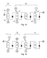
- FIG. 1a is a diagram of the first stage of a four-stage cycle implementing a simulated moving bed chromatographic process of the present invention.
- FIG. 1b is a diagram of the second stage of the cycle.
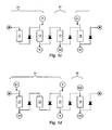
- FIG. 1c is a diagram of the third stage of the cycle.
- FIG. 1d is a diagram of the fourth stage of the cycle.
- FIG. 2 is a diagram of a system of chromatographic columns and inlet and outlet manifolds on which the cycle of FIGS. 1a through 1d can be performed.
- SMB system is used herein to denote the combination of fixed-bed columns, inlet and outlet valve manifolds, sources of feed mixture and of eluent, and mechanism for the timed switching of flows through the inlet and outlet manifolds, by way of which simulated moving bed chromatography is practiced.
- a typical SMB system is thus one that contains
- each column having an inlet manifold arranged to direct incoming flow from a plurality of inlet lines to the column and an outlet manifold arranged to direct flow emerging from the column to a plurality of discharge lines;
- a controller for all inlet and outlet valve manifolds that forms flow paths communicating each column with a selected inlet line and a selected discharge line, and for changing the inlet and discharge lines so selected at preselected time intervals.
- a single manifold can serve as both the outlet manifold of one column and the inlet manifold of another.
- the inlet manifold associated with each column preferably joins the column with at least three, and more preferably only three, inlet lines, while the outlet manifold associated with each column likewise preferably joins the column with at least three, and more preferably only three, discharge lines. Selections among the various lines in each manifold are achieved by conventional means, such as a remotely controlled on-off valve on each line or a remotely controlled multi-way valve.
- valve positions in each of the inlet and outlet manifolds are first configured to isolate a first group of columns from flow communication with a second group. Each group of columns will then have an upstream end and a downstream end.
- the columns can be divided into three or more isolated groups rather than just two, but division into two groups is preferred.
- eluent is passed through the second group of columns by feeding eluent to the upstream end of the second group and collecting eluent emerging from the downstream end.
- the flow rate of eluent through the second group is great enough to allow for complete elution of the most retained compound within the time allocated by the selected switching time of the SMB system.
- the flow rate through the second group can be fixed or variable, but using a flow rate that exceeds the average flow rate through the first group is preferred.
- valve positions in the inlet and outlet manifolds are reconfigured to advance all feed and withdrawal sites, and the divisions between the first and second groups of columns, in a common direction around the circuit, which is the same direction as the eluent flow.
- the new configuration is maintained for another selected time interval, which can either be of the same duration as the first or of a different duration, and the various sites of feeding and withdrawal, and the divisions between the two groups of columns, are advanced again.
- the pattern of introduction and withdrawal thus rotates around the column circuit in the same manner as the pattern movement in conventional SMB, but the pattern itself differs in the present invention by including the flow divisions that close off flow between the two groups of columns and that rotate with the introduction and withdrawal sites, and further by including two eluent introduction sites and two extract withdrawal sites, all of which operate concurrently with the feed introduction and raffinate withdrawal sites (between switch times).
- the eluent introduction site to the first group is referred to herein as the first introduction site, the extract withdrawal site in the first group as the first withdrawal site, the feed introduction site in the first group as the second introduction site, the raffinate withdrawal site in the first group as the second withdrawal site, the eluent introduction site to the second group as the third introduction site, and the extract withdrawal site in the second group as the third withdrawal site.
- group of columns is used herein to denote as little as one column (i.e ., a single unitary column with a continuous packed bed of solid phase), or even only part of one column, or two or more columns.
- adjacent pair in reference to introduction and withdrawal sites is used herein to refer to any pair of introduction and withdrawal sites that have no further introduction or withdrawal sites between them in the direction of eluent flow.
- the number of columns between any such adjacent pair can be either one column or two or more columns.
- the number of columns between any one adjacent pair can be the same as or different from the number of columns between any other adjacent pair.
- the number of columns between each adjacent pair of introduction/withdrawal sites, whichever such site is first in the direction of eluent flow is from one to six, and more preferably one to three.
- the number of columns in the first group (which includes feed introduction at the second introduction site and raffinate withdrawal at the second withdrawal site) is preferably from three to twelve, and more preferably from three to nine, while the number of columns in the second group (which does not include a feed introduction site nor a raffinate withdrawal site) is preferably from one to four, more preferably one or two.
- the total number of columns in the system preferably ranges from four to sixteen, and more preferably from four to eight.
- extract denotes a fraction of the initial liquid mixture that contains the component(s) that is/are more strongly retained on the solid phase relative to the other component(s) and that elute(s) in a relatively purified form, i.e ., relatively isolated from the less strongly retained component(s).
- raffinate denotes a fraction of the initial liquid mixture that contains the components(s) that is/are retained relatively weakly on the solid phase and that elute(s) in a relatively purified form, i.e ., relatively isolated from the strongly retained component(s).
- the present invention is operated in preferred embodiments with a single introduction site and a single withdrawal site in the second group of columns (which may contain a single column), as compared to three zones separated by introduction and withdrawal sites in the first group of columns (which will contain three or more columns), each zone operating at a different flow rate due to the intermediate introduction or withdrawal sites.
- the term "average flow rate" in reference to the first group of columns denotes the total of the flow rates through all columns of the first group divided by the number of columns in the first group. While the flow rates through the various portions of the system can vary widely at individual stage of operation, the present invention offers the advantage of allowing the use of a flow rate through the second group of columns that substantially exceeds the average flow rate through the first group of columns.
- the ratio of the flow rate through the second group to the average flow rate through the first group preferably ranges from about 1.0 to about 20.0, more preferably from about 2.0 to about 10.0, and most preferably from about 2.5 to about 6.0.
- the process of the invention is preferably operated at flow rates that produce a pressure drop across the second group of columns that is from about 1.0 to about 2.0 times, more preferably from about 1.0 to about 1.5 times, and most preferably from about the same as the pressure drop across the second group.
- the isolation points separating the two groups of columns and all introduction and withdrawal sites can be advanced either simultaneously or in an asynchronous or staged manner (as in the Varicol variation) or at variable flow rates (as in the PowerFeed variation). Simultaneous advancement is generally preferred.
- Operating parameters of the system such as time intervals between advancements of the various introduction and withdrawal sites, the lengths and widths of individual columns, pump pressures, and the mass or volumetric flow rate through each column, will generally be within the ranges used in SMB systems of the prior art, although with a higher flow rate through the second group of columns.
- Typical columns are packed-bed columns with lengths ranging from 5 to 15 and diameters ranging from 2 mm to 1,600 mm.
- Volumetric relative flow rates calculated per unit column cross section will generally be between 0.5 mL/min/cm 2 and 40 mL/min/cm 2 ; pump pressures will generally be between 2 bar and 60 bar, and switch times will generally be from about 0.15 minutes to about 15 minutes.
- FIGS. 1a through 1d represent the individual stages, respectively, of a four-stage cycle in which each adjacent pair of introduction/withdrawal sites is separated by one column.
- the entire solid phase thus resides in four columns 11, 12, 13, 14 , joined to form a circuit.
- the asterisk on the right side of the diagram joins the asterisk on the left side to complete the circuit
- the check valves indicate the direction of flow through the circuit
- the solid lines connecting the columns represent lines of liquid flow
- the dashed lines represent lines that are closed and not in use ( i.e ., liquid residing in these lines is not moving). While the inlet and outlet manifolds are not shown in FIGS. 1a through 1d , the flow paths shown by the various solid lines are achieved by appropriate positions of the valves in the manifolds.
- the valve positions are arranged such that the three columns on the right 12, 13, 14 , are in flow communication to define the "first group" 21 as this term is used above.
- the solution containing the components to be separated identified as the "feed” and indicated in the diagram by the symbol F , is introduced at the inlet 22 to the last column 14 in the first group ( i.e ., between the middle column 13 and the last column 14 ); the eluent, indicated in the diagram by the symbol E1 , is introduced at the entry 23 of the first column 12 in the first group; the ry, indicated in the diagram by the symbol X1 , is withdrawn at a withdrawal point 24 between the first column 12 and the middle column 13 in the first group, and the raffinate 25 , indicated in the diagram by the symbol R, is withdrawn at the outlet 25 from the last column 14 in the group.
- the raffinate 25 constitutes the entire stream passing through the last column 14 , and there is no recycle stream from the last column 14 to the first column 12 to supplement the eluent supply 23 .
- the column 11 on the extreme left of the diagram is defined as the "second group" 31 and is isolated from the first group, as indicated by the dashed lines. Both ends of the column 11 therefore serve as points of isolation of the column from the other columns.
- the rate of introduction of eluent E2 at the column inlet 32 is substantially greater than the flow rates through any of the three columns in the second group 21 , to achieve elution of the strongly retained component in the extract X2 . Extract is thus withdrawn from the system in two portions X1 and X2 , which may ultimately be combined as a product.
- the valve positions are shifted ("switched") such that the first, third, and fourth columns 11, 13, 14, according to the view shown in the diagram, are joined to constitute the "first group” 21 and the second column 12 is isolated from the other columns to serve as the "second group” 31 .
- the isolation, introduction, and withdrawal sites are thus all advanced by a distance of one column length in the direction of eluent flow.
- Corresponding advances are made for the third stage ( FIG. 1c ) and the fourth stage ( FIG. 1d ). An advance following the fourth stage returns the system to the first stage ( FIG. 1a ) and the cycle is repeated.
- FIGS. 2 is a diagram showing examples of inlet and outlet manifolds that allow the cycle of FIGS. 1a, 1b , 1c, and 1d to be performed.
- Each inlet manifold 41, 42, 43, 44 offers a choice between the feed F and the two eluent feeds E1, E2, and each outlet manifold 45, 46, 47, 48 offers a choice between the raffinate R and the two extracts X1, X2 .
- a system controller 51 controls the positions of the valves and the switch time.
- the controller software can be any of known software programs for laboratory instrumentation. Examples are VISUAL BASIC (Microsoft, Redmond Washington, USA) and LABVIEW (National Instruments, Austin, Texas, USA).
- variations on the cycle described above in connection with FIGS. 1a, 1b , 1c , and 1d include (1) recycling a portion of the extract stream X1 to the eluent introduction stream E1 ; (2) replacing each individual column in this example with two or more columns; (3) using a different number of columns in each zone ( i.e ., between each adjacent pair of introduction/withdrawal sites); (4) switching different introduction and withdrawal sites at different times rather than simultaneously (the Varicol technique); and (5) changing the flow rates at different times in the cycle (the PowerFeed technique).
- the PowerFeed technique changing the flow rates at different times in the cycle.
- a zone corresponding to Zone IV of conventional SMB systems is lacking from the system and protocol described in connection with this figures, such a zone can indeed be included as a further variation.
- Preferred systems of this invention do not include either a recycle stream or a zone corresponding to Zone IV. Still further variations will be apparent to those skilled in SMB systems.
Landscapes
- Chemical & Material Sciences (AREA)
- Life Sciences & Earth Sciences (AREA)
- Sustainable Development (AREA)
- Analytical Chemistry (AREA)
- Chemical Kinetics & Catalysis (AREA)
- Treatment Of Liquids With Adsorbents In General (AREA)
Claims (13)
- Verfahren zum Auftrennen von Spezies in einer flüssigen Lösung in ein Extrakt und ein Raffinat in einem Chromatographiesystem mit einem simulierten Wanderbett, wobei das System umfasst:eine Vielzahl von Packbettsäulen, die in einem Kreislauf in Reihe geschaltet sind,wobei jede Säule ein Einlasssammelrohr, das angeordnet ist, um den eingehenden Strom von einer Vielzahl von Eingangsleitungen zu der Säule zu leiten, und ein Auslasssammelrohr, das angeordnet ist, um den aus der Säule austretenden Strom zu einer Vielzahl von Austragungsleitungen zu leiten, aufweist,eine Zuführungsquelle für die flüssige Lösung,eine Quelle für den Eluenten, undMittel zum Steuern aller Einlass- und Auslasssammelrohre, um Strömungswege zu bilden, die jede Säule jeweils mit einer ausgewählten Eingangsleitung und mit einer ausgewählten Austragungsleitung verbinden und um die ausgewählten Eingangs- und Austragungsleitungen in vorgegebenen Zeitintervallen zu wechseln,wobei das Verfahren umfasst:(a) Konfigurieren der Einlass- und Auslasssammelrohre mittels einer Ventilsteuereinrichtung, um eine erste Gruppe an Säulen von der Strömungsverbindung mit einer zweiten Gruppe an Säulen abzutrennen, wobei jede Gruppe an Säulen ein stromaufwärts gelegenes Ende und ein stromabwärts gelegenes Ende aufweist, die zusammen eine Strömungsrichtung des Fluids durch den Kreislauf definieren,(b) wobei die Sammelrohre derart konfiguriert sind, dass sie die nachstehend angegebenen Schritte (i) bis (v) gleichzeitig durchführen:(i) Zuführen des Eluenten von der Quelle für den Eluenten zu der ersten Gruppe an Säulen durch ein Einlasssammelrohr am stromaufwärts gelegenen Ende der ersten Gruppe, wobei das stromaufwärts gelegene Ende als erste Einleitungsstelle definiert ist;(ii) Abziehen von Extrakt von der ersten Gruppe an Säulen durch ein Auslasssammelrohr an einer ersten Austragungsstelle zwischen dem stromaufwärts gelegenen Ende und dem stromabwärts gelegenen Ende der ersten Gruppe;(iii) Zuführen der flüssigen Lösung von der Zuführungsquelle zu der ersten Gruppe an Säulen durch ein Einlasssammelrohr zwischen der ersten Austragungsstelle und dem stromabwärts gelegenen Ende der ersten Gruppe, wobei dieses als zweite Einleitungsstelle definiert ist,(iv) Abziehen von Raffinat von der ersten Gruppe an Säulen durch ein Auslasssammelrohr am stromabwärts gelegenen Ende der ersten Gruppe, wobei das stromabwärts gelegene Ende als zweite Austragungsstelle definiert ist; und(v) Passierenlassen des Eluenten durch die zweite Gruppe an Säulen mit einer Strömungsgeschwindigkeit, die wesentlich größer ist als die mittlere Strömungsgeschwindigkeit durch die erste Gruppe an Säulen, wobei der Eluent am stromaufwärts gelegenen Ende der zweiten Gruppe zugeführt wird und wobei der Eluent, der am stromabwärts gelegenen Ende der zweiten Gruppe als weiterer Extrakt austritt, gesammelt wird, wobei das stromaufwärts gelegene Ende der zweiten Gruppe als dritte Einleitungsstelle definiert ist und das stromabwärts gelegene Ende als dritte Austragungsstelle definiert ist;(c) nach einem ausgewählten Zeitintervall Neukonfigurieren der Ventile der Einlass- und Auslasssammelrohre mit Hilfe der Steuermittel, um alle Einleitungs- und Austragungsstellen und damit die Säulen, die die erste und die zweite Gruppe bilden, in Strömungsrichtung vorwärts zu verschieben,(d) so langes Wiederholen der Schritte (b) und (c), bis alle Spezies in der flüssigen Mischung zwischen dem Extrakt und dem Raffinat verteilt sind.
- Verfahren nach Anspruch 1, wobei die Strömungsgeschwindigkeit des Eluenten, der in Schritt (v) die zweite Gruppe an Säulen passiert, etwa 1,0- bis etwa 20,0-mal so groß ist wie die mittlere Strömungsgeschwindigkeit durch die erste Gruppe an Säulen.
- Verfahren nach Anspruch 1, wobei die Strömungsgeschwindigkeit des Eluenten, der in Schritt (v) die zweite Gruppe an Säulen passiert, etwa 2,0- bis etwa 10,0-mal so groß ist wie die mittlere Strömungsgeschwindigkeit durch die erste Gruppe an Säulen.
- Verfahren nach Anspruch 1, wobei die Strömungsgeschwindigkeit des Eluenten, der in Schritt (v) die zweite Gruppe an Säulen passiert, etwa 2,5- bis etwa 6,0-mal so groß ist wie die mittlere Strömungsgeschwindigkeit durch die erste Gruppe an Säulen.
- Verfahren nach Anspruch 1, wobei das Raffinat, das in Schritt (iv) von der ersten Gruppe an Säulen abgezogen wird, jegliches Fluid enthält, das aus dem stromabwärts gelegenen Ende der ersten Gruppe an Säulen austritt.
- Verfahren nach Anspruch 1, wobei der Schritt (c) durchgeführt wird, indem alle Einleitungs- und Austragungsstellen gleichzeitig vorwärts verschoben werden.
- Verfahren nach Anspruch 1, wobei der Schritt (b) einen Druckabfall über die erste und die zweite Gruppe an Säulen verursacht und wobei der Druckabfall über die zweite Gruppe an Säulen etwa 1,0- bis etwa 2,0-mal so groß ist wie der Druckabfall über die erste Gruppe der Säulen.
- Verfahren nach Anspruch 1, wobei der Schritt (b) einen Druckabfall über die erste und die zweite Gruppe an Säulen verursacht und wobei der Druckabfall über die zweite Gruppe an Säulen etwa 1,0- bis etwa 1,5-mal so groß ist wie der Druckabfall über die erste Gruppe der Säulen.
- Verfahren nach Anspruch 1, wobei das System jeweils zwischen einer Einleitungsstelle und der am nächsten gelegenen Austragungsstelle in dem Kreislauf zwischen einer und sechs Säulen umfasst.
- Verfahren nach Anspruch 1, wobei das System zwischen jeder Einleitungsstelle und der am nächsten gelegenen Austragungsstelle in dem Kreislauf zwischen einer und drei Säulen umfasst.
- Verfahren nach Anspruch 1, wobei das System insgesamt zwischen vier und sechszehn Säulen aufweist.
- Verfahren nach Anspruch 1, wobei das System insgesamt zwischen vier und acht Säulen aufweist.
- Verfahren nach Anspruch 1, wobei jede Einleitungsstelle und die am nächsten gelegene Austragungsstelle in dem Kreislauf als benachbartes Paar an Einleitungs-/Austragungsstellen definiert ist und wobei die Anzahl an Säulen zwischen den jeweils benachbarten Paaren an Einleitungs-/Austragungsstellen bei den benachbarten Paaren jeweils nicht immer gleich ist.
Applications Claiming Priority (1)
| Application Number | Priority Date | Filing Date | Title |
|---|---|---|---|
| US12/059,651 US7618539B2 (en) | 2008-03-31 | 2008-03-31 | Simulated moving bed chromatography for strongly retained compounds |
Publications (2)
| Publication Number | Publication Date |
|---|---|
| EP2108423A1 EP2108423A1 (de) | 2009-10-14 |
| EP2108423B1 true EP2108423B1 (de) | 2011-07-06 |
Family
ID=40790743
Family Applications (1)
| Application Number | Title | Priority Date | Filing Date |
|---|---|---|---|
| EP09156353A Not-in-force EP2108423B1 (de) | 2008-03-31 | 2009-03-26 | Simulierte Wanderbett-Chromatografie für stark zurückgehaltene Verbindungen |
Country Status (3)
| Country | Link |
|---|---|
| US (1) | US7618539B2 (de) |
| EP (1) | EP2108423B1 (de) |
| AT (1) | ATE515302T1 (de) |
Cited By (1)
| Publication number | Priority date | Publication date | Assignee | Title |
|---|---|---|---|---|
| RU2583053C2 (ru) * | 2010-05-12 | 2016-05-10 | Эвоник Дегусса Гмбх | Способ отделения триптофана |
Families Citing this family (13)
| Publication number | Priority date | Publication date | Assignee | Title |
|---|---|---|---|---|
| KR101036554B1 (ko) | 2009-11-16 | 2011-05-24 | 인하대학교 산학협력단 | 4구역 모사이동층 크로마토그래피의 비동기적 시동방법 |
| US20130266706A1 (en) * | 2010-07-13 | 2013-10-10 | Nederlandse Organisatie Voor Toegepast- Natuurwetenschappelijk Onderzoek Tno | Methods and compositions for deacidifying fruit juice |
| EP2656892A1 (de) * | 2012-04-23 | 2013-10-30 | Merck Patent GmbH | Chromatographieverfahren |
| CN104056467B (zh) * | 2014-06-30 | 2016-08-24 | 许建中 | 五区串联超临界二氧化碳流体模拟移动床色谱装置及其操作方法 |
| GB201419852D0 (en) * | 2014-11-07 | 2014-12-24 | Dupont Nutrition Biosci Aps | Method |
| CN107106929B (zh) | 2014-12-31 | 2020-06-09 | 通用电气健康护理生物科学股份公司 | 用于模拟移动床层析的阀歧管 |
| CN105617714B (zh) * | 2015-12-31 | 2017-05-31 | 厦门大学 | 异步切换的三区带模拟移动床 |
| CN109633206B (zh) * | 2017-10-09 | 2021-03-02 | 中核兰州铀浓缩有限公司 | 六氟化铀气体流向保护传感器的模拟测试系统及方法 |
| TWI919355B (zh) * | 2018-07-02 | 2026-03-21 | 美商里珍納龍藥品有限公司 | 自混合物製備多肽之系統及方法 |
| CN109432822B (zh) * | 2018-11-14 | 2023-09-29 | 内蒙古伊泰煤基新材料研究院有限公司 | 一种高效模拟移动床设备以及高效模拟移动床工艺 |
| CN111841667B (zh) * | 2020-07-13 | 2022-02-08 | 姜春林 | 一种循环式双调模拟热流系统 |
| CN115259452B (zh) * | 2022-06-09 | 2023-08-18 | 北京环球中科水务科技股份有限公司 | 连续流模拟移动床污水特征离子深度处理装置及方法 |
| CN117244275A (zh) * | 2022-12-30 | 2023-12-19 | 西安蓝晓科技新材料股份有限公司 | 一种模拟移动床连续逆流提取装置及提取方法 |
Family Cites Families (15)
| Publication number | Priority date | Publication date | Assignee | Title |
|---|---|---|---|---|
| CH435298A (fr) | 1963-10-08 | 1967-05-15 | Gevaert Photo Prod Nv | Procédé de préparation de 3-acylamino-5-pyrazolones |
| US3839325A (en) | 1973-03-23 | 1974-10-01 | Gaf Corp | Synthesis of 4-sulfonamidophenyl hydrazines |
| JP3010816B2 (ja) | 1991-08-22 | 2000-02-21 | ダイセル化学工業株式会社 | 光学分割における光学異性体と溶媒との回収方法、溶媒の循環使用方法、および光学異性体の再利用方法 |
| JPH07106282B2 (ja) | 1992-09-28 | 1995-11-15 | 綜研化学株式会社 | 多成分混合物の分離精製方法及び装置 |
| FI96225C (fi) | 1993-01-26 | 1996-05-27 | Cultor Oy | Menetelmä melassin fraktioimiseksi |
| US5466823A (en) | 1993-11-30 | 1995-11-14 | G.D. Searle & Co. | Substituted pyrazolyl benzenesulfonamides |
| JPH07285889A (ja) | 1994-04-20 | 1995-10-31 | Daicel Chem Ind Ltd | 光学異性体の分離方法 |
| JPH09206502A (ja) | 1995-12-01 | 1997-08-12 | Daicel Chem Ind Ltd | 擬似移動床式分離装置 |
| US6011177A (en) | 1997-11-26 | 2000-01-04 | Aerojet-General Corporation | Process for 4-sulfonamidolphenyl hydrazines |
| US6372127B1 (en) | 2000-03-09 | 2002-04-16 | Daicel Chemical Industries, Ltd. | Simulated moving bed separation system |
| JP2004003935A (ja) | 2002-04-12 | 2004-01-08 | Daicel Chem Ind Ltd | 擬似移動床式クロマトグラフィー用光学異性体分離用充填剤 |
| US6843854B2 (en) | 2002-05-31 | 2005-01-18 | Purdue Research Foundation | Method and apparatus for separating a component from a mixture |
| KR100589122B1 (ko) * | 2004-04-06 | 2006-06-12 | 삼성토탈 주식회사 | 차압증가를 방지하기 위한 유사 이동층 흡착 분리 공정 및 그 시스템 |
| WO2007144476A1 (fr) | 2006-06-16 | 2007-12-21 | Groupe Novasep | Procede de separation sequence multicolonnes |
| US7806137B2 (en) * | 2006-08-30 | 2010-10-05 | Semba Biosciences, Inc. | Control system for simulated moving bed chromatography |
-
2008
- 2008-03-31 US US12/059,651 patent/US7618539B2/en active Active
-
2009
- 2009-03-26 AT AT09156353T patent/ATE515302T1/de not_active IP Right Cessation
- 2009-03-26 EP EP09156353A patent/EP2108423B1/de not_active Not-in-force
Cited By (1)
| Publication number | Priority date | Publication date | Assignee | Title |
|---|---|---|---|---|
| RU2583053C2 (ru) * | 2010-05-12 | 2016-05-10 | Эвоник Дегусса Гмбх | Способ отделения триптофана |
Also Published As
| Publication number | Publication date |
|---|---|
| ATE515302T1 (de) | 2011-07-15 |
| US20090242486A1 (en) | 2009-10-01 |
| US7618539B2 (en) | 2009-11-17 |
| EP2108423A1 (de) | 2009-10-14 |
Similar Documents
| Publication | Publication Date | Title |
|---|---|---|
| US7618539B2 (en) | Simulated moving bed chromatography for strongly retained compounds | |
| US7141172B2 (en) | Versatile simulated moving bed systems | |
| JP4966449B2 (ja) | 長さが変動性であるクロマトグラフィー帯域を用いる分離方法 | |
| US5705061A (en) | Simulated moving bed adsorptive separation apparatus | |
| Seidel‐Morgenstern et al. | New developments in simulated moving bed chromatography | |
| US7837881B2 (en) | Method and device for chromatographic purification | |
| US5565104A (en) | Small scale simulated moving bed separation process | |
| JP5023235B2 (ja) | 2以上の多成分の混合体を分離するための準連続的クロマトグラフの方法と対応する装置 | |
| RU2508930C2 (ru) | Способ многофракционной очистки и устройство для осуществления такого способа | |
| Nowak et al. | Theoretical study of using simulated moving bed chromatography to separate intermediately eluting target compounds | |
| US9180387B2 (en) | Method and device for separating fractions of a mixture | |
| US20060273013A1 (en) | Versatile simulated moving bed systems | |
| US20030094415A1 (en) | Preparative chromatography system and separation/purification method using same | |
| CN1326588C (zh) | 使用液-固接触器的高效连续反应/分离方法 | |
| WO2002040129A2 (en) | Systems and processes for performing separations using a simulated moving bed apparatus | |
| KR20180116629A (ko) | 푸코오스 분리방법 및 이를 위한 장치 | |
| EP0880984A1 (de) | Vorrichtung und Verfahren für adsorptive Trennung mit einem simulierten Wanderbett | |
| Lim et al. | Effect of dead volume on performance of simulated moving bed process | |
| US20250352925A1 (en) | Continuous fixed bed chromatography, adsorption, and ion exchange system | |
| Kaspereit et al. | Liquid Chromatography: Chapter 19. Process Concepts in Preparative Chromatography | |
| Colin et al. | Large-Scale Liquid Chromatography |
Legal Events
| Date | Code | Title | Description |
|---|---|---|---|
| PUAI | Public reference made under article 153(3) epc to a published international application that has entered the european phase |
Free format text: ORIGINAL CODE: 0009012 |
|
| 17P | Request for examination filed |
Effective date: 20090730 |
|
| AK | Designated contracting states |
Kind code of ref document: A1 Designated state(s): AT BE BG CH CY CZ DE DK EE ES FI FR GB GR HR HU IE IS IT LI LT LU LV MC MK MT NL NO PL PT RO SE SI SK TR |
|
| AX | Request for extension of the european patent |
Extension state: AL BA RS |
|
| AKX | Designation fees paid |
Designated state(s): AT BE BG CH CY CZ DE DK EE ES FI FR GB GR HR HU IE IS IT LI LT LU LV MC MK MT NL NO PL PT RO SE SI SK TR |
|
| GRAP | Despatch of communication of intention to grant a patent |
Free format text: ORIGINAL CODE: EPIDOSNIGR1 |
|
| RIC1 | Information provided on ipc code assigned before grant |
Ipc: B01D 15/18 20060101AFI20110203BHEP |
|
| GRAS | Grant fee paid |
Free format text: ORIGINAL CODE: EPIDOSNIGR3 |
|
| GRAA | (expected) grant |
Free format text: ORIGINAL CODE: 0009210 |
|
| AK | Designated contracting states |
Kind code of ref document: B1 Designated state(s): AT BE BG CH CY CZ DE DK EE ES FI FR GB GR HR HU IE IS IT LI LT LU LV MC MK MT NL NO PL PT RO SE SI SK TR |
|
| REG | Reference to a national code |
Ref country code: GB Ref legal event code: FG4D |
|
| REG | Reference to a national code |
Ref country code: CH Ref legal event code: EP |
|
| REG | Reference to a national code |
Ref country code: IE Ref legal event code: FG4D |
|
| REG | Reference to a national code |
Ref country code: DE Ref legal event code: R096 Ref document number: 602009001719 Country of ref document: DE Effective date: 20110825 |
|
| REG | Reference to a national code |
Ref country code: CH Ref legal event code: NV Representative=s name: HEPP WENGER RYFFEL AG |
|
| REG | Reference to a national code |
Ref country code: NL Ref legal event code: VDEP Effective date: 20110706 |
|
| PG25 | Lapsed in a contracting state [announced via postgrant information from national office to epo] |
Ref country code: SI Free format text: LAPSE BECAUSE OF FAILURE TO SUBMIT A TRANSLATION OF THE DESCRIPTION OR TO PAY THE FEE WITHIN THE PRESCRIBED TIME-LIMIT Effective date: 20110706 |
|
| REG | Reference to a national code |
Ref country code: AT Ref legal event code: MK05 Ref document number: 515302 Country of ref document: AT Kind code of ref document: T Effective date: 20110706 |
|
| PG25 | Lapsed in a contracting state [announced via postgrant information from national office to epo] |
Ref country code: LT Free format text: LAPSE BECAUSE OF FAILURE TO SUBMIT A TRANSLATION OF THE DESCRIPTION OR TO PAY THE FEE WITHIN THE PRESCRIBED TIME-LIMIT Effective date: 20110706 Ref country code: NO Free format text: LAPSE BECAUSE OF FAILURE TO SUBMIT A TRANSLATION OF THE DESCRIPTION OR TO PAY THE FEE WITHIN THE PRESCRIBED TIME-LIMIT Effective date: 20111006 Ref country code: IS Free format text: LAPSE BECAUSE OF FAILURE TO SUBMIT A TRANSLATION OF THE DESCRIPTION OR TO PAY THE FEE WITHIN THE PRESCRIBED TIME-LIMIT Effective date: 20111106 Ref country code: HR Free format text: LAPSE BECAUSE OF FAILURE TO SUBMIT A TRANSLATION OF THE DESCRIPTION OR TO PAY THE FEE WITHIN THE PRESCRIBED TIME-LIMIT Effective date: 20110706 Ref country code: SE Free format text: LAPSE BECAUSE OF FAILURE TO SUBMIT A TRANSLATION OF THE DESCRIPTION OR TO PAY THE FEE WITHIN THE PRESCRIBED TIME-LIMIT Effective date: 20110706 Ref country code: PT Free format text: LAPSE BECAUSE OF FAILURE TO SUBMIT A TRANSLATION OF THE DESCRIPTION OR TO PAY THE FEE WITHIN THE PRESCRIBED TIME-LIMIT Effective date: 20111107 Ref country code: NL Free format text: LAPSE BECAUSE OF FAILURE TO SUBMIT A TRANSLATION OF THE DESCRIPTION OR TO PAY THE FEE WITHIN THE PRESCRIBED TIME-LIMIT Effective date: 20110706 Ref country code: FI Free format text: LAPSE BECAUSE OF FAILURE TO SUBMIT A TRANSLATION OF THE DESCRIPTION OR TO PAY THE FEE WITHIN THE PRESCRIBED TIME-LIMIT Effective date: 20110706 |
|
| PG25 | Lapsed in a contracting state [announced via postgrant information from national office to epo] |
Ref country code: AT Free format text: LAPSE BECAUSE OF FAILURE TO SUBMIT A TRANSLATION OF THE DESCRIPTION OR TO PAY THE FEE WITHIN THE PRESCRIBED TIME-LIMIT Effective date: 20110706 Ref country code: PL Free format text: LAPSE BECAUSE OF FAILURE TO SUBMIT A TRANSLATION OF THE DESCRIPTION OR TO PAY THE FEE WITHIN THE PRESCRIBED TIME-LIMIT Effective date: 20110706 Ref country code: LV Free format text: LAPSE BECAUSE OF FAILURE TO SUBMIT A TRANSLATION OF THE DESCRIPTION OR TO PAY THE FEE WITHIN THE PRESCRIBED TIME-LIMIT Effective date: 20110706 Ref country code: GR Free format text: LAPSE BECAUSE OF FAILURE TO SUBMIT A TRANSLATION OF THE DESCRIPTION OR TO PAY THE FEE WITHIN THE PRESCRIBED TIME-LIMIT Effective date: 20111007 Ref country code: CY Free format text: LAPSE BECAUSE OF FAILURE TO SUBMIT A TRANSLATION OF THE DESCRIPTION OR TO PAY THE FEE WITHIN THE PRESCRIBED TIME-LIMIT Effective date: 20110706 |
|
| PG25 | Lapsed in a contracting state [announced via postgrant information from national office to epo] |
Ref country code: SK Free format text: LAPSE BECAUSE OF FAILURE TO SUBMIT A TRANSLATION OF THE DESCRIPTION OR TO PAY THE FEE WITHIN THE PRESCRIBED TIME-LIMIT Effective date: 20110706 Ref country code: CZ Free format text: LAPSE BECAUSE OF FAILURE TO SUBMIT A TRANSLATION OF THE DESCRIPTION OR TO PAY THE FEE WITHIN THE PRESCRIBED TIME-LIMIT Effective date: 20110706 |
|
| PGFP | Annual fee paid to national office [announced via postgrant information from national office to epo] |
Ref country code: FR Payment date: 20120319 Year of fee payment: 4 Ref country code: IE Payment date: 20120312 Year of fee payment: 4 |
|
| PLBE | No opposition filed within time limit |
Free format text: ORIGINAL CODE: 0009261 |
|
| STAA | Information on the status of an ep patent application or granted ep patent |
Free format text: STATUS: NO OPPOSITION FILED WITHIN TIME LIMIT |
|
| PG25 | Lapsed in a contracting state [announced via postgrant information from national office to epo] |
Ref country code: EE Free format text: LAPSE BECAUSE OF FAILURE TO SUBMIT A TRANSLATION OF THE DESCRIPTION OR TO PAY THE FEE WITHIN THE PRESCRIBED TIME-LIMIT Effective date: 20110706 Ref country code: RO Free format text: LAPSE BECAUSE OF FAILURE TO SUBMIT A TRANSLATION OF THE DESCRIPTION OR TO PAY THE FEE WITHIN THE PRESCRIBED TIME-LIMIT Effective date: 20110706 Ref country code: IT Free format text: LAPSE BECAUSE OF FAILURE TO SUBMIT A TRANSLATION OF THE DESCRIPTION OR TO PAY THE FEE WITHIN THE PRESCRIBED TIME-LIMIT Effective date: 20110706 |
|
| 26N | No opposition filed |
Effective date: 20120411 |
|
| PG25 | Lapsed in a contracting state [announced via postgrant information from national office to epo] |
Ref country code: DK Free format text: LAPSE BECAUSE OF FAILURE TO SUBMIT A TRANSLATION OF THE DESCRIPTION OR TO PAY THE FEE WITHIN THE PRESCRIBED TIME-LIMIT Effective date: 20110706 |
|
| PGFP | Annual fee paid to national office [announced via postgrant information from national office to epo] |
Ref country code: DE Payment date: 20120411 Year of fee payment: 4 |
|
| REG | Reference to a national code |
Ref country code: DE Ref legal event code: R097 Ref document number: 602009001719 Country of ref document: DE Effective date: 20120411 |
|
| BERE | Be: lapsed |
Owner name: AMPAC FINE CHEMICALS LLC Effective date: 20120331 |
|
| PG25 | Lapsed in a contracting state [announced via postgrant information from national office to epo] |
Ref country code: MC Free format text: LAPSE BECAUSE OF NON-PAYMENT OF DUE FEES Effective date: 20120331 |
|
| PG25 | Lapsed in a contracting state [announced via postgrant information from national office to epo] |
Ref country code: BE Free format text: LAPSE BECAUSE OF NON-PAYMENT OF DUE FEES Effective date: 20120331 |
|
| PG25 | Lapsed in a contracting state [announced via postgrant information from national office to epo] |
Ref country code: MK Free format text: LAPSE BECAUSE OF FAILURE TO SUBMIT A TRANSLATION OF THE DESCRIPTION OR TO PAY THE FEE WITHIN THE PRESCRIBED TIME-LIMIT Effective date: 20110706 |
|
| PG25 | Lapsed in a contracting state [announced via postgrant information from national office to epo] |
Ref country code: ES Free format text: LAPSE BECAUSE OF FAILURE TO SUBMIT A TRANSLATION OF THE DESCRIPTION OR TO PAY THE FEE WITHIN THE PRESCRIBED TIME-LIMIT Effective date: 20111017 |
|
| PG25 | Lapsed in a contracting state [announced via postgrant information from national office to epo] |
Ref country code: BG Free format text: LAPSE BECAUSE OF FAILURE TO SUBMIT A TRANSLATION OF THE DESCRIPTION OR TO PAY THE FEE WITHIN THE PRESCRIBED TIME-LIMIT Effective date: 20111006 |
|
| PG25 | Lapsed in a contracting state [announced via postgrant information from national office to epo] |
Ref country code: MT Free format text: LAPSE BECAUSE OF FAILURE TO SUBMIT A TRANSLATION OF THE DESCRIPTION OR TO PAY THE FEE WITHIN THE PRESCRIBED TIME-LIMIT Effective date: 20110706 |
|
| REG | Reference to a national code |
Ref country code: CH Ref legal event code: PL |
|
| GBPC | Gb: european patent ceased through non-payment of renewal fee |
Effective date: 20130326 |
|
| REG | Reference to a national code |
Ref country code: FR Ref legal event code: ST Effective date: 20131129 |
|
| REG | Reference to a national code |
Ref country code: IE Ref legal event code: MM4A |
|
| REG | Reference to a national code |
Ref country code: DE Ref legal event code: R119 Ref document number: 602009001719 Country of ref document: DE Effective date: 20131001 |
|
| PG25 | Lapsed in a contracting state [announced via postgrant information from national office to epo] |
Ref country code: IE Free format text: LAPSE BECAUSE OF NON-PAYMENT OF DUE FEES Effective date: 20130326 Ref country code: DE Free format text: LAPSE BECAUSE OF NON-PAYMENT OF DUE FEES Effective date: 20131001 Ref country code: GB Free format text: LAPSE BECAUSE OF NON-PAYMENT OF DUE FEES Effective date: 20130326 Ref country code: LI Free format text: LAPSE BECAUSE OF NON-PAYMENT OF DUE FEES Effective date: 20130331 Ref country code: CH Free format text: LAPSE BECAUSE OF NON-PAYMENT OF DUE FEES Effective date: 20130331 Ref country code: FR Free format text: LAPSE BECAUSE OF NON-PAYMENT OF DUE FEES Effective date: 20130402 |
|
| PG25 | Lapsed in a contracting state [announced via postgrant information from national office to epo] |
Ref country code: TR Free format text: LAPSE BECAUSE OF FAILURE TO SUBMIT A TRANSLATION OF THE DESCRIPTION OR TO PAY THE FEE WITHIN THE PRESCRIBED TIME-LIMIT Effective date: 20110706 |
|
| PG25 | Lapsed in a contracting state [announced via postgrant information from national office to epo] |
Ref country code: LU Free format text: LAPSE BECAUSE OF NON-PAYMENT OF DUE FEES Effective date: 20120326 |
|
| PG25 | Lapsed in a contracting state [announced via postgrant information from national office to epo] |
Ref country code: HU Free format text: LAPSE BECAUSE OF FAILURE TO SUBMIT A TRANSLATION OF THE DESCRIPTION OR TO PAY THE FEE WITHIN THE PRESCRIBED TIME-LIMIT Effective date: 20090326 |