EP2108531B1 - Pneumatischer Reifen - Google Patents
Pneumatischer Reifen Download PDFInfo
- Publication number
- EP2108531B1 EP2108531B1 EP09005096A EP09005096A EP2108531B1 EP 2108531 B1 EP2108531 B1 EP 2108531B1 EP 09005096 A EP09005096 A EP 09005096A EP 09005096 A EP09005096 A EP 09005096A EP 2108531 B1 EP2108531 B1 EP 2108531B1
- Authority
- EP
- European Patent Office
- Prior art keywords
- tire
- grooves
- groove
- circumferential direction
- tread
- Prior art date
- Legal status (The legal status is an assumption and is not a legal conclusion. Google has not performed a legal analysis and makes no representation as to the accuracy of the status listed.)
- Not-in-force
Links
- 238000010586 diagram Methods 0.000 description 5
- 238000012360 testing method Methods 0.000 description 4
- 230000000052 comparative effect Effects 0.000 description 3
- 230000006866 deterioration Effects 0.000 description 3
- 230000007423 decrease Effects 0.000 description 2
- 230000000694 effects Effects 0.000 description 2
- 238000002474 experimental method Methods 0.000 description 2
- 238000012986 modification Methods 0.000 description 2
- 230000004048 modification Effects 0.000 description 2
- 238000013459 approach Methods 0.000 description 1
- 230000008602 contraction Effects 0.000 description 1
- 238000012937 correction Methods 0.000 description 1
- 238000006073 displacement reaction Methods 0.000 description 1
- 238000011156 evaluation Methods 0.000 description 1
- 230000001953 sensory effect Effects 0.000 description 1
- 238000009736 wetting Methods 0.000 description 1
Images



Classifications
-
- B—PERFORMING OPERATIONS; TRANSPORTING
- B60—VEHICLES IN GENERAL
- B60C—VEHICLE TYRES; TYRE INFLATION; TYRE CHANGING; CONNECTING VALVES TO INFLATABLE ELASTIC BODIES IN GENERAL; DEVICES OR ARRANGEMENTS RELATED TO TYRES
- B60C11/00—Tyre tread bands; Tread patterns; Anti-skid inserts
- B60C11/03—Tread patterns
- B60C11/0302—Tread patterns directional pattern, i.e. with main rolling direction
-
- B—PERFORMING OPERATIONS; TRANSPORTING
- B60—VEHICLES IN GENERAL
- B60C—VEHICLE TYRES; TYRE INFLATION; TYRE CHANGING; CONNECTING VALVES TO INFLATABLE ELASTIC BODIES IN GENERAL; DEVICES OR ARRANGEMENTS RELATED TO TYRES
- B60C11/00—Tyre tread bands; Tread patterns; Anti-skid inserts
- B60C11/03—Tread patterns
- B60C11/0306—Patterns comprising block rows or discontinuous ribs
-
- B—PERFORMING OPERATIONS; TRANSPORTING
- B60—VEHICLES IN GENERAL
- B60C—VEHICLE TYRES; TYRE INFLATION; TYRE CHANGING; CONNECTING VALVES TO INFLATABLE ELASTIC BODIES IN GENERAL; DEVICES OR ARRANGEMENTS RELATED TO TYRES
- B60C11/00—Tyre tread bands; Tread patterns; Anti-skid inserts
- B60C11/03—Tread patterns
- B60C11/13—Tread patterns characterised by the groove cross-section, e.g. for buttressing or preventing stone-trapping
-
- B—PERFORMING OPERATIONS; TRANSPORTING
- B60—VEHICLES IN GENERAL
- B60C—VEHICLE TYRES; TYRE INFLATION; TYRE CHANGING; CONNECTING VALVES TO INFLATABLE ELASTIC BODIES IN GENERAL; DEVICES OR ARRANGEMENTS RELATED TO TYRES
- B60C11/00—Tyre tread bands; Tread patterns; Anti-skid inserts
- B60C11/03—Tread patterns
- B60C2011/0337—Tread patterns characterised by particular design features of the pattern
- B60C2011/0339—Grooves
- B60C2011/0358—Lateral grooves, i.e. having an angle of 45 to 90 degees to the equatorial plane
- B60C2011/0367—Lateral grooves, i.e. having an angle of 45 to 90 degees to the equatorial plane characterised by depth
- B60C2011/0369—Lateral grooves, i.e. having an angle of 45 to 90 degees to the equatorial plane characterised by depth with varying depth of the groove
-
- B—PERFORMING OPERATIONS; TRANSPORTING
- B60—VEHICLES IN GENERAL
- B60C—VEHICLE TYRES; TYRE INFLATION; TYRE CHANGING; CONNECTING VALVES TO INFLATABLE ELASTIC BODIES IN GENERAL; DEVICES OR ARRANGEMENTS RELATED TO TYRES
- B60C11/00—Tyre tread bands; Tread patterns; Anti-skid inserts
- B60C11/03—Tread patterns
- B60C2011/0337—Tread patterns characterised by particular design features of the pattern
- B60C2011/0339—Grooves
- B60C2011/0381—Blind or isolated grooves
-
- B—PERFORMING OPERATIONS; TRANSPORTING
- B60—VEHICLES IN GENERAL
- B60C—VEHICLE TYRES; TYRE INFLATION; TYRE CHANGING; CONNECTING VALVES TO INFLATABLE ELASTIC BODIES IN GENERAL; DEVICES OR ARRANGEMENTS RELATED TO TYRES
- B60C11/00—Tyre tread bands; Tread patterns; Anti-skid inserts
- B60C11/03—Tread patterns
- B60C2011/0337—Tread patterns characterised by particular design features of the pattern
- B60C2011/0339—Grooves
- B60C2011/0381—Blind or isolated grooves
- B60C2011/0383—Blind or isolated grooves at the centre of the tread
-
- B—PERFORMING OPERATIONS; TRANSPORTING
- B60—VEHICLES IN GENERAL
- B60C—VEHICLE TYRES; TYRE INFLATION; TYRE CHANGING; CONNECTING VALVES TO INFLATABLE ELASTIC BODIES IN GENERAL; DEVICES OR ARRANGEMENTS RELATED TO TYRES
- B60C11/00—Tyre tread bands; Tread patterns; Anti-skid inserts
- B60C11/03—Tread patterns
- B60C2011/0337—Tread patterns characterised by particular design features of the pattern
- B60C2011/0386—Continuous ribs
- B60C2011/0388—Continuous ribs provided at the equatorial plane
-
- B—PERFORMING OPERATIONS; TRANSPORTING
- B60—VEHICLES IN GENERAL
- B60C—VEHICLE TYRES; TYRE INFLATION; TYRE CHANGING; CONNECTING VALVES TO INFLATABLE ELASTIC BODIES IN GENERAL; DEVICES OR ARRANGEMENTS RELATED TO TYRES
- B60C11/00—Tyre tread bands; Tread patterns; Anti-skid inserts
- B60C11/03—Tread patterns
- B60C11/13—Tread patterns characterised by the groove cross-section, e.g. for buttressing or preventing stone-trapping
- B60C11/1307—Tread patterns characterised by the groove cross-section, e.g. for buttressing or preventing stone-trapping with special features of the groove walls
- B60C2011/1338—Tread patterns characterised by the groove cross-section, e.g. for buttressing or preventing stone-trapping with special features of the groove walls comprising protrusions
Definitions
- the present invention relates to a pneumatic tire having a tread pattern including at least three circumferential grooves extending in a tire circumferential direction.
- JP 2710341 B discloses a pneumatic tire in which tire blocks are arranged alternately with respect to circumferentially adjacent blocks.
- An advantage obtainable with embodiments of the present invention is to provide a pneumatic tire capable of attaining both a reduction in tire noise and an improvement in on-snow performance and, in particular, a pneumatic tire having a feature in terms of a pattern.
- a pneumatic tire (hereinafter, simply referred to as tire) according to an embodiment of the present invention is an SUV tire.
- the dimension example employed in the following description is mainly that for a 265/70R17 tire, and it is a dimension example that can be effectively employed for a tire with a nominal tire width of 175 to 305.
- the tire has in a tread portion thereof a tread pattern 10 constituting a feature of the present invention.
- FIG. 1A is an easy-to-see developed view of the tread pattern 10 of the tire.
- the tire structure and rubber member may be well-known ones or novel ones.
- the tread pattern 10 is of a non-line-symmetrical configuration with respect to a tire center CL passing a tire equatorial plane, and it is of a point-symmetrical configuration. It is not always necessary for the tread pattern to be of the point-symmetrical configuration.
- tire width direction refers to a direction of a tire rotation center axis
- tire circumferential direction refers to a rotating direction of a rotating plane of a tread surface formed by rotating the tire around the tire rotation center axis. Those directions are illustrated in FIG. 1A .
- the term "tread width” refers to a maximum tread width in the tire width direction as obtained when the tire is caused to tread on a horizontal surface under an inner pressure condition of 200 kPa and under a load condition which is 85% of the load capacity under a pressure of 200 kPa as specified in JATMA, TRA, or ETRTO.
- a circumferential groove which extends in the tire circumferential direction, is a groove whose groove width ranges from 6 to 18 mm and whose groove depth ranges from 6.0 to 16.0 mm.
- the tread pattern 10 mainly includes a first land portion 12 which extends in the tire circumferential direction and through which the tire center CL passes, first main grooves 14 adjacent to both sides of the first land portion 12 and extending in a communicating manner in the tire circumferential direction, second land portions 16 provided adjacent to outer sides in the tire width direction of the first main grooves 14 and extending in the tire circumferential direction, second main grooves 18 provided adjacent to the outer sides in the tire width direction of the second land portions 16 and extending in a communicating manner in the tire circumferential direction, and third land portions 20 provided on the outer sides in the tire width direction of the second main grooves 18 and extending in the tire circumferential direction.
- the first land portion 12 has a rib-like configuration extending continuously in the tire circumferential direction and is provided with lug grooves 22 formed at fixed intervals extending from the first main grooves 18 toward the first land portions 12.
- the lug grooves 22 are closed halfway through without extending across the center line CL.
- the lug grooves 22 are inclined, for example, by 20 to 40 degrees with respect to the tire width direction.
- the first land portion 12 has two sipes 24 in every interval between circumferentially adjacent lug grooves 12. Further, the ends of the first land portion 12 in contact with the first main grooves 14 are formed as zigzag-shaped steps by point heights 26 described below. At the portions recessed due to the zigzag-shaped steps, the sipes 24 are provided at the same inclination angle as the lug grooves 22.
- the first main grooves 14 are provided so as to be within a range of 15% of the tire tread width from the tire center CL.
- providing the first main grooves 14 so as to be within a range of 15% of the tire tread width means that the center positions in the groove width direction of the first main grooves 14 are situated within the range of 15% of the tire tread width.
- the positions of the main grooves are specified in terms of tread width, it means that the center positions in the groove width direction of the main grooves are specified.
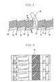
- FIG. 1B is a schematic explanatory view of the point heights 26.
- the sipes 24 are omitted from illustrated.
- the point heights 26 are formed on both side groove walls 28 and 30 forming each first main groove 14 such that first inclined walls 32 and second inclined walls 34 are continuously connected in the tire circumferential direction.
- the connecting portions between the first inclined walls 32 and the second inclined walls 34 are bent in a V-shape.
- the length of the first inclined walls 32 is larger than the length of the second inclined walls 34, and a step amount ⁇ in the tire width direction between two first inclined walls 32 on both sides of one second inclined wall 34 is 1.5 to 5.0 mm.
- the ratio of the length of the first inclined walls 32 to that of the second inclined walls 34 is desirable for the ratio of the length of the first inclined walls 32 to that of the second inclined walls 34 to range from 4 to 10.
- any snow entering the first main grooves 14 can be efficiently discharged. That is, when certain portions in the tire periphery of the first main grooves 14 approach the vicinity of the tread surface, and snow enters the first main grooves 14, the snow having entered is compressed due to contraction of the grooves occurred through passage of the above-mentioned portions of the first main grooves 14 over the tread surface. At this time, the compressed snow moves to the right (direction in which the groove width is increased) along the first inclined walls 32 in FIG. 2 .
- Each of the second land portions 16 has a rib-like configuration extending continuously in the tire circumferential direction and is provided with arcuate curved grooves 38 and lug grooves 40 formed at fixed intervals extending from the second main grooves 18 toward the second land portions 16 in an arcuate or elliptical fashion.
- the lug grooves 40 are closed halfway through.
- the lug grooves 40 are inclined, for example, by 10 to 30 degrees with respect to the tire width direction.
- the groove length of the lug grooves 40 is 5 to 15 mm.
- the arcuate curved grooves 38 are inclined by 5 to 45 degrees and, more preferably, 15 to 35 degrees, with respect to the tire width direction at openings leading to the second main grooves 18, and extend to the second land portions 16.
- the arcuate curved grooves 38 extending from the second main groove 18 on one side with respect to the tire center CL extend in opposite direction from that of the arcuate curved grooves 38 extending from the second main groove 18 on the other side with respect thereto. That is, the arcuate curved grooves 38 on the right-hand side of the center line CL in FIG. 1A extend downwards from the second main groove 18, whereas the arcuate curved grooves 38 on the left-hand side of the center line CL extend upwardly from the second main groove 18.
- each arcuate curved groove 38 does not communicate with the first main grooves 14, nor does it communicate with the other arcuate curved grooves 38 adjacent thereto, which means there is no pass-through portion, thereby achieving a reduction in tire noise.
- the second land portions 16 are provided with sipes 42, which are inclined in the tire circumferential direction with respect to the tire width direction from the closed portions of the lug grooves 40, and connected to the first main grooves 14 in a gentle arc. Further, the second land portions 16 are provided with another sipes 44, which extend from the first main grooves 14 in the same inclining direction as the sipes 42 but are closed halfway through.
- the second land portions 16 there exist no lug grooves extend across the same. Further, when they pass the tread surface, the sipes 42 and 44 are closed, and hence the second land portions 16 have a function similar to that of the rib-shaped land portions continuous in the tire circumferential direction. Thus, it is possible to achieve a reduction in tire noise.
- the reason for providing the sipes 42 and 44 is to adjust, immediately before the certain portions on the tire periphery of the second land portions 16 having the sipes 42 and 44 come into contact with the ground (pass the tread surface) through rotation of the tire, the incident angle when certain portions of the second land portions 16 move obliquely with respect to the ground by the sipes 42 and 44, which extend across the second land portions 16 in the tire width direction.
- the above-mentioned point heights 26 are provided at the ends of the second land portions 16 in contact with the first main groove 14, and hence the ends of the land portions are of a zigzag configuration.
- point heights 46 on the wall portions of the second main grooves 18, and hence those ends of the land portions are also of a zigzag configuration.
- the arcuate curved grooves 38 and the lug grooves 40 there are provided the arcuate curved grooves 38 and the lug grooves 40, and hence the steps at those portions are not to be visually recognized.
- imaginary lines which are extensions of the groove walls of the second main grooves 18, in the portions that are not to be visually recognized, it is possible to confirm the presence of the zigzag-shaped steps.
- the point heights 46 are of the same configuration as the point heights 26, and hence a description thereof is omitted. Further, also on the walls of the point heights 46, there are provided minute groove wall groups similar to the minute groove groups 36 as illustrated in FIG. 2 , making it possible to easily discharge the compressed snow.
- three pairs of first and second adjacent inclined walls are provided in one tread pattern pitch determined between the adjacent lug grooves 40.
- the number of pairs is not restricted to three, and it is possible to provide the pairs up to five pairs.
- the minute groove groups provided on the first inclined walls of the point heights 46 are inclined so as to extend toward the tread surface.
- the inclination angle ⁇ of the minute groove groups in the tire circumferential direction is preferably 10 to 80 degrees and, more preferably, 30 to 60 degrees.
- the third land portions 20 are provided adjacent to the second main grooves 18, and correspond to shoulder regions of the tire. At the end of each third land portion 20 in contact with the second main groove 18, there are provided the above-mentioned point heights 46, and hence the end of the land portion 20 is of a zigzag configuration. At the step portions of a zigzag configuration, lug grooves 48 extend from the second main grooves 18. The lug grooves 48 are closed halfway through. The lug grooves 48 are positioned so as to extend the arcuate curved grooves 38 to the third land portions 20. In addition, they are inclined by 60 to 90 degrees with respect to the tire circumferential direction.
- minute groove groups similar to the minute groove groups 36 so as to be inclined with respect to the tire circumferential direction.
- the minute groove groups are inclined so as to extend toward the tread surface as extending toward the direction in which the groove width of the second main grooves 18 formed by the first inclined walls increases.
- the inclination angle ⁇ of the minute groove groups is 10 and 80 degrees and, more preferably, 30 to 60 degrees.
- Sipes 54 are provided to extend from the closed portions of the lug grooves 50 so as to be connected to the second main grooves 18. On the other hand, there are provided sipes 54 extending from the closed portions of the lug grooves 54 to be connected to the lug grooves 48.
- the reason for thus providing no lug grooves extending across the third land portions 20 is to achieve a reduction in tire noise. There exist no lug grooves extending across the third land portions 20. Further, the sipes 52 and 54 are closed when they pass the tread surface through rotation of the tire, and hence the third land portions 20 have a function similar to that of the rib-shaped land portions continuous in the tire circumferential direction, and do not reduce the tread rigidity in the tire circumferential direction of the third land portions 20.
- the reason for providing the sipes 52 and 54 is to adjust by the sipes 52 and 54 the incident angle when the surfaces of certain portions of the third land portions 20 move obliquely with respect to the ground immediately before the above-mentioned portions of the third land portions 20 on the tire periphery of the third land portions 20 having the sipes 52 and 54 are brought into contact with the ground (pass the tread surface) through rotation of the tire.
- the lug grooves 48 are provided in the step portions of a zigzag configuration due to the point heights 46, and hence, although those portions are not to be visually recognized, by drawing imaginary lines, which are extensions of the groove walls of the second main grooves 18, it is possible to confirm the presence of the step portions of a zigzag configuration.
- the inclination angle of the first inclined walls 32 with respect to the tire circumferential direction is 5 to 20 degrees. However, it is more desirable for the angle to be 10 to 15 degrees.
- the inclination angle of the second inclined walls 34 with respect to the tire width direction is 0 to 45 degrees. However, it is more desirable for the angle to be 10 to 30 degrees.
- the first inclined walls of main groove group (first circumferential groove group) of the first main grooves 14 and the second main grooves 18 situated on the right-hand side in the tire width direction of the tire center CL are all inclined in the same direction with respect to the tire circumferential direction, and the first inclined walls of the main groove group (second circumferential groove group) situated on the left-hand side of the tire width direction are also all inclined in the same direction with respect to the tire circumferential direction.
- the inclining direction of the first inclined walls of the main groove group (first circumferential groove group) situated on the right-hand side of the tire center CL with respect to the tire width direction be the same as the inclining direction of the first inclined walls of the main groove group (second circumferential groove group) situated on the left-hand side of the same.
- the first main grooves 14 are provided within 15% of the tread width as measured from the tire center CL. This is due to the fact that, when the first main grooves 14 are provided on the outer sides of the positions corresponding to 15% of the tread width, the first land portion 12 is too large, resulting in deterioration in wetting performance, in particular, draining performance.
- the second main grooves 18 are provided within 20 to 40% of the tread width as measured from the tire center CL. This is due to the fact that, when the second main grooves 18 are provided on the tire center CL side of the positions corresponding to 20% of the tread width of the second main grooves 18, the width of the second land portions 18 is reduced, whereby the tread rigidity of those portions is lowered, with the result that uneven wear easily occurs. Further, when the second main grooves 18 are provided on the sides opposite to the tire center CL with respect to the positions corresponding to 40% of the tread width, the third land portions 20 become smaller, whereby the rigidity of those portions is lowered, resulting in deterioration in controllability.
- the lug grooves provided in the first land portion 12, the second land portions 16, and the third land portions 20 are lug grooves closed halfway through. That is, there exist no lug grooves leading to the main grooves adjacent to the land portions. As a result, the pattern noise generated by the lug grooves is reduced, and the tire noise is markedly reduced.
- a ratio with respect to the tread area of the groove area of see-through portions of the first main grooves 14 and the second main grooves 18, which are circumferential grooves be 15 to 30%.
- the term "see-through" portion refers to the portion excluding those portions that cannot be seen through, that is, the portion that can be seen through. In the example of FIG. 1B , the see-through portion is the portion indicated by symbol X.
- minute groove groups are provided in the first inclined walls, whereby it is possible to achieve an improvement in on-snow performance without affecting the other performances.
- the point heights are provided in each of the circumferential grooves extending in the tire circumferential direction, it is also possible to adopt a tire in which the point heights are provided in one of the circumferential grooves. Note that it is desirable for the zigzag-shaped bent portions formed by the point heights to be provided 150 to 400 in number to at least one groove wall in the tire circumferential direction.
- a first circumferential groove is provided at the tire tread center CL, and one second circumferential groove is provided on either side in the tire width direction of this central circumferential groove.
- the second circumferential grooves it is desirable for the second circumferential grooves to be provided so as to be within a range of 25 to 35% of the tire tread width as measured from the tire center CL.
- the tire size was 265/70R17 115H.
- the prepared tires had the following tread pattern, with their rims being 17 ⁇ 8J.
- the vehicle used to examine tire performance was an SUV vehicle with an engine displacement on the order of 6 liters.
- the inner pressure condition was 210 kPa for both the front and rear wheels.
- Pattern a is a pattern as illustrated in FIG. 1A
- patterns b through d are modifications based on the pattern a.
- Table 1 illustrates the specifications of patterns a through d.
- FIGS. 4 through 6 illustrate patterns b through d, respectively.
- Pattern a FIG. 1A With lug grooves 22 and sipes 24 With point heights 26 With lug grooves 40, arcuate curved grooves 38, and sipes 42 and 44 With point heights 46 With lug grooves 48, 50, and 56 and sipes 52 and 54
- Pattern b FIG.
- the point heights provided on the walls of the first main grooves of the pattern d have two bent portions per pitch, which means the requirement that there should be provided three to five pairs of first and second inclined walls in one pitch as restricted in embodiments of the present invention, that is, the requirement that there should be provided three to five bent portions, is not satisfied.
- the tires with the patterns a or b are ones according to the present invention (examples), and the tires with the patterns c or d are not ones according to the present invention (comparative examples).
- the tire test was conducted for on-snow performance and tire noise.
- each tire was evaluated by measuring a requisite braking distance for stopping the vehicle when braking was effected when the vehicle was traveling at a traveling speed of 40 km/h on a snow-covered road in an outdoor testing site.
- correction was effected on the values of five braking distances. Of those values, those of the maximum braking distance and of the minimum braking distance were excluded, and the average value of the remaining three braking distances was obtained.
- deceleration was effected in a natural manner from a traveling speed of 80 km/h on a dry road surface in the tire testing site, and the magnitude of the sound pressure of in-vehicle pattern noise was evaluated through sensory evaluation made by the driver.
- Table 2 illustrates the test results. Each result is indicated by an index. The larger the index, the more satisfactory the on-snow performance and the tire noise performance. [Table 2] On-snow performance Tire noise performance Pattern a 108 120 Pattern b 110 115 Pattern c 95 100 Pattern d 100 100
- the tread pattern 10 of the tire has the first land portion 12 provided on the tire center CL, the first main grooves 14 provided adjacent to both sides of the first land portion 12 within a range of 15% of the tire tread width as measured from the tire center CL, the second land portions 16 provided adjacent to outer sides of the first main grooves 14, and the second main grooves 18 provided adjacent to the outer sides of the second land portions 16 within a range of 20 to 40% of the tire tread width as measured from the tire center CL.
- it is not limited to the above structure.
- the tread pattern 10 of the tire may include a first circumferential groove provided at a tire tread center position, that is, on the tire center CL, and second circumferential grooves provided each on either side in the tire width direction of the first circumferential groove within a range of 15 to 45% of a tire tread width as measured from the tire center CL.
- the groove walls of the circumferential grooves are formed by the first inclined walls and the second inclined walls, and point heights bent in a V-shape are provided at the connection portions between the first inclined walls and the second inclined walls, with three to five point height bent portions being provided per one tread pattern pitch, whereby it is possible to attain compatibility between a reduction in tire noise and an improvement in on-snow performance.
Landscapes
- Engineering & Computer Science (AREA)
- Mechanical Engineering (AREA)
- Tires In General (AREA)
- Transition And Organic Metals Composition Catalysts For Addition Polymerization (AREA)
- Pharmaceuticals Containing Other Organic And Inorganic Compounds (AREA)
- Acyclic And Carbocyclic Compounds In Medicinal Compositions (AREA)
Claims (11)
- Luftreifen, der ein Laufflächenmuster (10) aufweist, das wenigstens drei Umfangsrillen (14, 18) mit einer Rillenbreite von 6 bis 18 mm und einer Rillentiefe von 6,0 bis 16,0 mm umfasst, die sich in einer Reifenumfangsrichtung erstrecken,
bei dem bezüglich Rillenwände (28, 30) auf beiden Seiten, welche die wenigstens drei Umfangsrillen (14, 18) ausbilden, erste geneigte Wände (32), die relativ zur Reifenumfangsrichtung um einen Neigungswinkel von 5 bis 20° geneigt sind, und zweite geneigte Wände (34), die relativ zur Reifenbreitenrichtung um einen Neigungswinkel von 0 bis 45° geneigt sind, vorgesehen sind, um in der Reifenumfangsrichtung so der Reihe nach verbunden zu sein, dass Positionen von Rillenenden bezüglich der Reifenbreitenrichtung in der Reifenumfangsrichtung variieren,
Verbindungsabschnitte zwischen den ersten geneigten Wänden (32) und den zweiten geneigten Wänden (34) in einer Draufsicht des Laufflächenmusters (10) V-förmig gebogen sind,
eine Länge der ersten geneigten Wände (32) größer als eine Länge der zweiten geneigten Wände (34) ist,
jede zweite der ersten geneigten Wände (32) auf beiden Seiten jeder zweiten geneigten Wand (34) einen Stufenbetrag (Δ) von 1,5 bis 5,0 mm in der Reifenbreitenrichtung aufweist, dadurch gekennzeichnet, dass
Nebenrillen (22, 40, 48), die sich von den wenigstens drei Umfangsrillen (14, 18) erstrecken, in festen Abständen in der Reifenumfangsrichtung vorgesehen sind, und
drei bis fünf Paare der ersten geneigten Wände (32) und der zweiten geneigten Wände (34), die benachbart zueinander sind, in einem Abstandsmaß des Laufflächenmusters vorgesehen sind, das von den benachbarten Nebenrillen (22, 40, 48) bestimmt wird. - Luftreifen nach Anspruch 1, bei dem die ersten geneigten Rillen (32) von gegenüberliegenden Wänden (28, 30) auf beiden Seiten von jeder der wenigstens drei Umfangsrillen (14, 18) relativ zur Reifenumfangsrichtung in der gleichen Richtung geneigt sind.
- Luftreifen nach Anspruch 1 oder 2, bei dem die ersten geneigten Wände (32) auf wenigstens einer Seite der wenigstens drei Umfangsrillen (14, 18) mit winzigen Rillengruppen (36) vorgesehen sind, die sich von einer Umgebung eines Rillenbodens von jeder der wenigstens drei Umfangsrillen (14, 18) zu einer Lauffläche erstrecken und so vorgesehen sind, um relativ zur Reifenumfangsrichtung geneigt zu sein, wobei die winzigen Rillengruppen (36) so geneigt sind, um sich bei Erstreckung in einer Richtung, in der die Rillenbreite der wenigstens drei Umfangsrillen (14, 18), die von den ersten geneigten Wänden (32) ausgebildet werden, sich vergrößert, zur Laufflächenoberfläche erstrecken.
- Luftreifen nach Anspruch 3, bei dem der Neigungswinkel der winzigen Rillengruppen 10 bis 80° relativ zur Reifenumfangsrichtung beträgt.
- Luftreifen nach Anspruch 3 oder 4, bei dem die wenigstens drei Umfangsrillen (14, 18)
eine erste Umfangsrille (14), die an einer mittleren Reifenlaufflächenposition vorgesehen ist, und
zweite Umfangsrillen (18) umfassen, die jeweils auf einer Seite in der Reifenbreitenrichtung der ersten Umfangsrille vorgesehen sind, und
wobei die zweiten Umfangsrillen (18) innerhalb eines Bereichs von 15 bis 45% einer Reifenlaufflächenbreite gemessen von der mittleren Reifenlaufflächenposition vorgesehen sind. - Luftreifen nach einem der Ansprüche 1 bis 4, ferner umfassend:einen ersten Bodenabschnitt (12), durch den eine mittlere Reifenposition (CL) tritt und der sich in der Reifenumfangsrichtung erstreckt; undzweite Bodenabschnitte (16), die auf beiden Seiten des ersten Bodenabschnitts (12) vorgesehen sind, der sich in der Reifenumfangsrichtung erstreckt;die wenigstens drei Umfangsrillen (14, 18), welche erste Hauptrillen (14), die zwischen dem ersten Bodenabschnitt (12) und den zweiten Bodenabschnitten (16) vorgesehen sind, und zweite Hauptrillen (18) umfassen, die in der Reifenbreitenrichtung benachbart zu Außenseiten der zweiten Bodenabschnitte (16) vorgesehen sind,wobei die ersten Hauptrillen (14) innerhalb eines Bereichs von 15% der Reifenlaufflächenbreite gemessen von der mittleren Reifenposition (CL) vorgesehen sind;die zweiten Hauptrillen (18) innerhalb eines Bereichs von 20 bis 40% der Reifenlaufflächenbreite gemessen von der mittleren Reifenposition (CL) vorgesehen sind.
- Luftreifen nach Anspruch 6,
bei dem die zweiten Bodenabschnitte (16) mit bogenförmig gekrümmten Rillen (38) vorgesehen sind, die sich von den zweiten Hauptrillen (18) erstrecken, wobei die bogenförmig gekrümmten Rillen (38) geschlossen sind, ohne mit den ersten Hauptrillen (14) in Kommunikation zu stehen, die bogenförmig gekrümmten Rillen (38) in dem zweiten Bodenabschnitt (16) auf einer Seite der mittleren Reifenposition (CL) sich in entgegengesetzte Richtungen bezüglich der bogenförmig gekrümmten Rillen (38) in dem zweiten Bodenabschnitt (16) auf der anderen Seite der mittleren Reifenposition (CL) erstrecken. - Luftreifen nach Anspruch 6 oder 7, bei dem ein Verhältnis eines Rillenflächenbereichs von Abschnitten der freien Sicht der ersten Hauptrillen (14) und der zweiten Hauptrillen (18) bezüglich des Laufflächenbereichs 15 bis 30% beträgt.
- Luftreifen nach einem der Ansprüche 6 bis 8, der ferner dritte Bodenabschnitte (20) umfasst, die in der Reifenbreitenrichtung auf Außenseiten der zweiten Bodenabschnitte (16) vorgesehen sind und sich in der Reifenumfangsrichtung erstrecken,
wobei der erste Bodenabschnitt (12), die zweiten Bodenabschnitte (16) und die dritten Bodenabschnitte (20) so vorgesehen sind, um sich in der Reifenumfangsrichtung kontinuierlich zu erstrecken, während diese nicht mit sich darüber erstreckenden Nebenrillen vorgesehen sind. - Luftreifen nach Anspruch 9, bei dem die dritten Bodenabschnitte (20) in der Reifenumfangsrichtung eine Mehrzahl von ersten Nebenrillen (48), die sich von den zweiten Hauptrillen (18) zu den Reifenschulterseiten erstrecken und auf halbem Wege geschlossen sind, und eine Mehrzahl von zweiten Nebenrillen (50) umfassen, die sich von den Reifenschulterseiten zu den zweiten Hauptrillen erstrecken und auf halbem Wege geschlossen sind, wobei eine Nebenrille (50) zwischen jeweils zwei benachbarten ersten Nebenrillen (48) vorgesehen ist.
- Luftreifen nach Anspruch 9 oder 10, bei dem eine Mehrzahl von winzigen Rillengruppen (24, 42, 44, 52, 54), die relativ zur Reifenumfangsrichtung geneigt sind, auf einer Lauffläche des ersten Bodenabschnitts (12) und/oder der zweiten Bodenabschnitte (16) und/oder der dritten Bodenabschnitte (20) vorgesehen sind.
Applications Claiming Priority (1)
| Application Number | Priority Date | Filing Date | Title |
|---|---|---|---|
| JP2008103491A JP4488083B2 (ja) | 2008-04-11 | 2008-04-11 | 空気入りタイヤ |
Publications (3)
| Publication Number | Publication Date |
|---|---|
| EP2108531A2 EP2108531A2 (de) | 2009-10-14 |
| EP2108531A3 EP2108531A3 (de) | 2010-03-24 |
| EP2108531B1 true EP2108531B1 (de) | 2011-02-02 |
Family
ID=40589884
Family Applications (1)
| Application Number | Title | Priority Date | Filing Date |
|---|---|---|---|
| EP09005096A Not-in-force EP2108531B1 (de) | 2008-04-11 | 2009-04-07 | Pneumatischer Reifen |
Country Status (6)
| Country | Link |
|---|---|
| US (1) | US8281830B2 (de) |
| EP (1) | EP2108531B1 (de) |
| JP (1) | JP4488083B2 (de) |
| CN (1) | CN101554829B (de) |
| AT (1) | ATE497448T1 (de) |
| DE (1) | DE602009000692D1 (de) |
Families Citing this family (57)
| Publication number | Priority date | Publication date | Assignee | Title |
|---|---|---|---|---|
| US9278582B2 (en) * | 2010-12-21 | 2016-03-08 | Bridgestone Americas Tire Operations, Llc | Tire tread having developing grooves |
| JP5287894B2 (ja) * | 2011-02-08 | 2013-09-11 | 横浜ゴム株式会社 | 空気入りタイヤ |
| IT1404060B1 (it) * | 2011-02-14 | 2013-11-08 | Bridgestone Corp | Striscia di battistrada con scanalature asimmetriche per ridurre la ritenzione di detriti |
| JP5452561B2 (ja) * | 2011-09-16 | 2014-03-26 | 住友ゴム工業株式会社 | 空気入りタイヤ |
| JP6056359B2 (ja) * | 2012-10-11 | 2017-01-11 | 横浜ゴム株式会社 | 空気入りタイヤ |
| AU2014227282B2 (en) | 2013-03-06 | 2016-03-17 | The Yokohama Rubber Co., Ltd. | Pneumatic tire |
| JP5890796B2 (ja) * | 2013-04-11 | 2016-03-22 | 住友ゴム工業株式会社 | 空気入りタイヤ |
| BR112016000234B1 (pt) * | 2013-07-16 | 2021-08-24 | Pirelli Tyre S.P.A | Pneu de carro |
| MX375685B (es) | 2013-11-12 | 2025-03-06 | Goodyear Tire & Rubber | Banda de rodamiento de neumático que incluye estrías en cavidades hendidas de la pared lateral ranurada. |
| JP5938030B2 (ja) | 2013-12-27 | 2016-06-22 | 住友ゴム工業株式会社 | 空気入りタイヤ |
| JP6317140B2 (ja) * | 2014-03-05 | 2018-04-25 | 株式会社ブリヂストン | 空気入りタイヤ |
| US10179483B2 (en) | 2014-05-01 | 2019-01-15 | The Yokohama Rubber Co., Ltd. | Pneumatic tire |
| JP6344088B2 (ja) * | 2014-06-25 | 2018-06-20 | 横浜ゴム株式会社 | 空気入りタイヤ |
| JP6010589B2 (ja) * | 2014-08-07 | 2016-10-19 | 住友ゴム工業株式会社 | 空気入りタイヤ |
| US11203234B2 (en) * | 2014-08-12 | 2021-12-21 | The Yokohama Rubber Co., Ltd. | Pneumatic tire |
| JP6114731B2 (ja) * | 2014-10-31 | 2017-04-12 | 住友ゴム工業株式会社 | 空気入りタイヤ |
| JP6047137B2 (ja) * | 2014-11-20 | 2016-12-21 | 住友ゴム工業株式会社 | 空気入りタイヤ |
| FR3030371A1 (fr) * | 2014-12-23 | 2016-06-24 | Michelin & Cie | Bande de roulement pour pneu hivernal poids lourd |
| JP6063918B2 (ja) * | 2014-12-26 | 2017-01-18 | 住友ゴム工業株式会社 | 空気入りタイヤ |
| DE102015200234A1 (de) * | 2015-01-12 | 2016-07-14 | Continental Reifen Deutschland Gmbh | Fahrzeugluftreifen |
| DE102015211013A1 (de) | 2015-06-16 | 2016-12-22 | Continental Reifen Deutschland Gmbh | Fahrzeugluftreifen |
| USD796423S1 (en) | 2015-08-18 | 2017-09-05 | Bridgestone Americas Tire Operations, Llc | Tire tread |
| JP6555040B2 (ja) * | 2015-09-16 | 2019-08-07 | 住友ゴム工業株式会社 | タイヤ |
| JP6701919B2 (ja) * | 2016-04-26 | 2020-05-27 | 横浜ゴム株式会社 | 空気入りタイヤ |
| JP6744146B2 (ja) * | 2016-06-16 | 2020-08-19 | 株式会社ブリヂストン | タイヤ |
| JP2018034628A (ja) * | 2016-08-31 | 2018-03-08 | 横浜ゴム株式会社 | 空気入りタイヤ |
| JP6759929B2 (ja) * | 2016-09-26 | 2020-09-23 | 住友ゴム工業株式会社 | 空気入りタイヤ |
| JP6819277B2 (ja) * | 2016-12-22 | 2021-01-27 | 住友ゴム工業株式会社 | タイヤ |
| JP6891556B2 (ja) * | 2017-03-14 | 2021-06-18 | 住友ゴム工業株式会社 | タイヤ |
| JP6825434B2 (ja) * | 2017-03-16 | 2021-02-03 | 住友ゴム工業株式会社 | タイヤ |
| JP6834729B2 (ja) * | 2017-04-11 | 2021-02-24 | 住友ゴム工業株式会社 | 空気入りタイヤ |
| JP6720921B2 (ja) | 2017-05-29 | 2020-07-08 | 横浜ゴム株式会社 | 空気入りタイヤ |
| JP6607230B2 (ja) * | 2017-05-29 | 2019-11-20 | 横浜ゴム株式会社 | 空気入りタイヤ |
| JP6993815B2 (ja) * | 2017-08-31 | 2022-01-14 | Toyo Tire株式会社 | 空気入りタイヤ |
| JP6916067B2 (ja) * | 2017-08-31 | 2021-08-11 | Toyo Tire株式会社 | 空気入りタイヤ |
| JP6962125B2 (ja) * | 2017-10-12 | 2021-11-05 | 横浜ゴム株式会社 | 空気入りタイヤ |
| JP6993203B2 (ja) | 2017-12-13 | 2022-02-10 | Toyo Tire株式会社 | 空気入りタイヤ |
| JP6980515B2 (ja) * | 2017-12-26 | 2021-12-15 | Toyo Tire株式会社 | 空気入りタイヤ |
| JP7003780B2 (ja) | 2018-03-26 | 2022-01-21 | 横浜ゴム株式会社 | 空気入りタイヤ |
| JP6969474B2 (ja) * | 2018-03-26 | 2021-11-24 | 横浜ゴム株式会社 | 空気入りタイヤ |
| US11104182B2 (en) * | 2018-04-10 | 2021-08-31 | Sumitomo Rubber Industries, Ltd. | Tire |
| JP7066516B2 (ja) | 2018-05-17 | 2022-05-13 | Toyo Tire株式会社 | 空気入りタイヤ |
| US12214621B2 (en) * | 2018-07-13 | 2025-02-04 | The Yokohama Rubber Co., Ltd. | Pneumatic tire |
| RU2752536C1 (ru) * | 2018-07-13 | 2021-07-29 | Дзе Йокогама Раббер Ко., Лтд. | Пневматическая шина |
| JP7092591B2 (ja) * | 2018-07-26 | 2022-06-28 | Toyo Tire株式会社 | 空気入りタイヤ |
| JP7110858B2 (ja) * | 2018-09-18 | 2022-08-02 | 横浜ゴム株式会社 | 空気入りタイヤ |
| DE102018216560A1 (de) * | 2018-09-27 | 2020-04-02 | Continental Reifen Deutschland Gmbh | Fahrzeugluftreifen |
| JP7155847B2 (ja) * | 2018-10-12 | 2022-10-19 | 住友ゴム工業株式会社 | タイヤ |
| CN111791651B (zh) * | 2019-04-03 | 2024-06-07 | 住友橡胶工业株式会社 | 轮胎 |
| CN110239286A (zh) * | 2019-05-09 | 2019-09-17 | 正新橡胶(中国)有限公司 | 一种充气轮胎 |
| US11298982B2 (en) | 2019-08-29 | 2022-04-12 | The Goodyear Tire & Rubber Company | Tread for a pneumatic tire |
| FR3117935A1 (fr) * | 2020-12-17 | 2022-06-24 | Compagnie Generale Des Etablissements Michelin | Bande de roulement de pneumatique pour un véhicule lourd à robustesse améliorée |
| FR3117934A1 (fr) * | 2020-12-17 | 2022-06-24 | Compagnie Generale Des Etablissements Michelin | Bande de roulement de pneumatique pour un véhicule lourd à robustesse améliorée |
| JP7473849B2 (ja) * | 2020-12-28 | 2024-04-24 | 横浜ゴム株式会社 | 空気入りタイヤ |
| CN116648360A (zh) * | 2020-12-28 | 2023-08-25 | 横滨橡胶株式会社 | 充气轮胎 |
| DE102021200630A1 (de) * | 2021-01-25 | 2022-07-28 | Continental Reifen Deutschland Gmbh | Fahrzeugluftreifen |
| CN113306346B (zh) * | 2021-06-30 | 2023-01-24 | 赛轮集团股份有限公司 | 轮胎 |
Family Cites Families (22)
| Publication number | Priority date | Publication date | Assignee | Title |
|---|---|---|---|---|
| GB460038A (en) * | 1935-07-23 | 1937-01-20 | Hector Mazzeo | Improvements in or relating to the manufacture of rubber products |
| NL79068C (de) * | 1936-01-25 | |||
| US3115919A (en) * | 1962-04-27 | 1963-12-31 | Armstrong Rubber Co | Tire tread |
| IN138692B (de) * | 1973-03-08 | 1976-03-13 | Firestone Tire & Rubber Co | |
| US4807679A (en) | 1987-06-11 | 1989-02-28 | The Goodyear Tire & Rubber Company | Pneumatic tire tread having sipes |
| US4926919A (en) * | 1988-11-14 | 1990-05-22 | The Goodyear Tire & Rubber Company | Vehicle tire with rib type tread pattern having sipes across the ribs |
| JPH02175302A (ja) * | 1988-12-27 | 1990-07-06 | Bridgestone Corp | 空気入りタイヤ |
| DE4138687C2 (de) * | 1991-11-25 | 1995-09-14 | Pirelli Reifenwerke | Laufflächenprofil für einen Fahrzeugreifen |
| JPH0655913A (ja) * | 1992-08-07 | 1994-03-01 | Bridgestone Corp | 空気入りタイヤ |
| JPH06183214A (ja) * | 1992-12-22 | 1994-07-05 | Yokohama Rubber Co Ltd:The | 空気入りラジアルタイヤ |
| JP3421114B2 (ja) | 1993-11-22 | 2003-06-30 | 株式会社ブリヂストン | 空気入りタイヤ |
| JP3361256B2 (ja) * | 1997-09-30 | 2003-01-07 | 住友ゴム工業株式会社 | 雪路用空気入りタイヤ |
| JP4149034B2 (ja) | 1998-06-02 | 2008-09-10 | 住友ゴム工業株式会社 | 車両用タイヤ |
| BR0016036A (pt) * | 1999-12-01 | 2002-07-30 | Pirelli | Pneu para rodas de veìculos |
| US6866076B2 (en) * | 2000-02-07 | 2005-03-15 | Bridgestone Corporation | Tire having longitudinally extending smaller grooves formed in the walls of a groove |
| JP2003182315A (ja) * | 2001-12-25 | 2003-07-03 | Bridgestone Corp | 空気入りタイヤ |
| WO2004005051A1 (ja) * | 2002-07-05 | 2004-01-15 | The Yokohama Rubber Co.,Ltd. | 氷雪路用空気入りタイヤ |
| JP4522790B2 (ja) * | 2004-08-31 | 2010-08-11 | 住友ゴム工業株式会社 | 空気入りタイヤ |
| JP4581732B2 (ja) | 2005-02-16 | 2010-11-17 | 横浜ゴム株式会社 | 空気入りタイヤ |
| JP2007015655A (ja) | 2005-07-11 | 2007-01-25 | Yokohama Rubber Co Ltd:The | 空気入りタイヤ |
| JP5038649B2 (ja) * | 2006-04-18 | 2012-10-03 | 東洋ゴム工業株式会社 | 空気入りタイヤ |
| JP4500320B2 (ja) | 2007-02-07 | 2010-07-14 | 東洋ゴム工業株式会社 | 空気入りタイヤ |
-
2008
- 2008-04-11 JP JP2008103491A patent/JP4488083B2/ja active Active
-
2009
- 2009-04-07 EP EP09005096A patent/EP2108531B1/de not_active Not-in-force
- 2009-04-07 AT AT09005096T patent/ATE497448T1/de not_active IP Right Cessation
- 2009-04-07 DE DE602009000692T patent/DE602009000692D1/de active Active
- 2009-04-08 US US12/420,565 patent/US8281830B2/en not_active Expired - Fee Related
- 2009-04-10 CN CN2009101299467A patent/CN101554829B/zh not_active Expired - Fee Related
Also Published As
| Publication number | Publication date |
|---|---|
| US20090255614A1 (en) | 2009-10-15 |
| EP2108531A3 (de) | 2010-03-24 |
| DE602009000692D1 (de) | 2011-03-17 |
| US8281830B2 (en) | 2012-10-09 |
| CN101554829B (zh) | 2013-01-23 |
| CN101554829A (zh) | 2009-10-14 |
| EP2108531A2 (de) | 2009-10-14 |
| ATE497448T1 (de) | 2011-02-15 |
| JP4488083B2 (ja) | 2010-06-23 |
| JP2009248961A (ja) | 2009-10-29 |
Similar Documents
| Publication | Publication Date | Title |
|---|---|---|
| US8281830B2 (en) | Pneumatic tire with tread pattern including land portions having rib-like configurations | |
| EP2163405B1 (de) | Luftreifen | |
| EP2199111B1 (de) | Luftreifen mit Lamellen | |
| US10894446B2 (en) | Tire | |
| EP2193935B1 (de) | Luftreifen mit asymmetrischem Profilmuster | |
| US6626215B2 (en) | Pneumatic tire including long and narrow blocks with at least two sipes | |
| US8813800B2 (en) | Pneumatic tire | |
| KR100915110B1 (ko) | 공기 타이어 | |
| EP2058144B1 (de) | Luftreifen | |
| US9731555B2 (en) | Pneumatic tire | |
| CN105711342A (zh) | 充气轮胎 | |
| JP4488119B2 (ja) | 空気入りタイヤ | |
| JPH04232106A (ja) | タイヤトレッド | |
| US12179515B2 (en) | Pneumatic tire | |
| JP4595503B2 (ja) | 空気入りタイヤ | |
| EP3025878B1 (de) | Schwerlastluftreifen | |
| EP3828011B1 (de) | Reifenlauffläche | |
| CN104512205B (zh) | 充气轮胎 | |
| JP5282479B2 (ja) | 空気入りタイヤ | |
| EP4079540B1 (de) | Reifen | |
| JP2007238060A (ja) | 空気入りタイヤ | |
| EP3708387B1 (de) | Reifen zum fahren auf unebenem gelände | |
| CN112976954A (zh) | 轮胎 | |
| JP2021091362A (ja) | 空気入りタイヤ | |
| US11505006B2 (en) | Tyre |
Legal Events
| Date | Code | Title | Description |
|---|---|---|---|
| PUAI | Public reference made under article 153(3) epc to a published international application that has entered the european phase |
Free format text: ORIGINAL CODE: 0009012 |
|
| AK | Designated contracting states |
Kind code of ref document: A2 Designated state(s): AT BE BG CH CY CZ DE DK EE ES FI FR GB GR HR HU IE IS IT LI LT LU LV MC MK MT NL NO PL PT RO SE SI SK TR |
|
| PUAL | Search report despatched |
Free format text: ORIGINAL CODE: 0009013 |
|
| AK | Designated contracting states |
Kind code of ref document: A3 Designated state(s): AT BE BG CH CY CZ DE DK EE ES FI FR GB GR HR HU IE IS IT LI LT LU LV MC MK MT NL NO PL PT RO SE SI SK TR |
|
| AX | Request for extension of the european patent |
Extension state: AL BA RS |
|
| 17P | Request for examination filed |
Effective date: 20100721 |
|
| GRAP | Despatch of communication of intention to grant a patent |
Free format text: ORIGINAL CODE: EPIDOSNIGR1 |
|
| GRAS | Grant fee paid |
Free format text: ORIGINAL CODE: EPIDOSNIGR3 |
|
| GRAA | (expected) grant |
Free format text: ORIGINAL CODE: 0009210 |
|
| AK | Designated contracting states |
Kind code of ref document: B1 Designated state(s): AT BE BG CH CY CZ DE DK EE ES FI FR GB GR HR HU IE IS IT LI LT LU LV MC MK MT NL NO PL PT RO SE SI SK TR |
|
| REG | Reference to a national code |
Ref country code: GB Ref legal event code: FG4D |
|
| REG | Reference to a national code |
Ref country code: CH Ref legal event code: EP |
|
| REG | Reference to a national code |
Ref country code: IE Ref legal event code: FG4D |
|
| REF | Corresponds to: |
Ref document number: 602009000692 Country of ref document: DE Date of ref document: 20110317 Kind code of ref document: P |
|
| REG | Reference to a national code |
Ref country code: DE Ref legal event code: R096 Ref document number: 602009000692 Country of ref document: DE Effective date: 20110317 |
|
| REG | Reference to a national code |
Ref country code: NL Ref legal event code: VDEP Effective date: 20110202 |
|
| LTIE | Lt: invalidation of european patent or patent extension |
Effective date: 20110202 |
|
| PG25 | Lapsed in a contracting state [announced via postgrant information from national office to epo] |
Ref country code: IS Free format text: LAPSE BECAUSE OF FAILURE TO SUBMIT A TRANSLATION OF THE DESCRIPTION OR TO PAY THE FEE WITHIN THE PRESCRIBED TIME-LIMIT Effective date: 20110602 Ref country code: LT Free format text: LAPSE BECAUSE OF FAILURE TO SUBMIT A TRANSLATION OF THE DESCRIPTION OR TO PAY THE FEE WITHIN THE PRESCRIBED TIME-LIMIT Effective date: 20110202 Ref country code: NO Free format text: LAPSE BECAUSE OF FAILURE TO SUBMIT A TRANSLATION OF THE DESCRIPTION OR TO PAY THE FEE WITHIN THE PRESCRIBED TIME-LIMIT Effective date: 20110502 Ref country code: GR Free format text: LAPSE BECAUSE OF FAILURE TO SUBMIT A TRANSLATION OF THE DESCRIPTION OR TO PAY THE FEE WITHIN THE PRESCRIBED TIME-LIMIT Effective date: 20110503 Ref country code: ES Free format text: LAPSE BECAUSE OF FAILURE TO SUBMIT A TRANSLATION OF THE DESCRIPTION OR TO PAY THE FEE WITHIN THE PRESCRIBED TIME-LIMIT Effective date: 20110513 Ref country code: PT Free format text: LAPSE BECAUSE OF FAILURE TO SUBMIT A TRANSLATION OF THE DESCRIPTION OR TO PAY THE FEE WITHIN THE PRESCRIBED TIME-LIMIT Effective date: 20110602 Ref country code: SE Free format text: LAPSE BECAUSE OF FAILURE TO SUBMIT A TRANSLATION OF THE DESCRIPTION OR TO PAY THE FEE WITHIN THE PRESCRIBED TIME-LIMIT Effective date: 20110202 Ref country code: LV Free format text: LAPSE BECAUSE OF FAILURE TO SUBMIT A TRANSLATION OF THE DESCRIPTION OR TO PAY THE FEE WITHIN THE PRESCRIBED TIME-LIMIT Effective date: 20110202 Ref country code: HR Free format text: LAPSE BECAUSE OF FAILURE TO SUBMIT A TRANSLATION OF THE DESCRIPTION OR TO PAY THE FEE WITHIN THE PRESCRIBED TIME-LIMIT Effective date: 20110202 |
|
| PG25 | Lapsed in a contracting state [announced via postgrant information from national office to epo] |
Ref country code: FI Free format text: LAPSE BECAUSE OF FAILURE TO SUBMIT A TRANSLATION OF THE DESCRIPTION OR TO PAY THE FEE WITHIN THE PRESCRIBED TIME-LIMIT Effective date: 20110202 Ref country code: PL Free format text: LAPSE BECAUSE OF FAILURE TO SUBMIT A TRANSLATION OF THE DESCRIPTION OR TO PAY THE FEE WITHIN THE PRESCRIBED TIME-LIMIT Effective date: 20110202 Ref country code: BE Free format text: LAPSE BECAUSE OF FAILURE TO SUBMIT A TRANSLATION OF THE DESCRIPTION OR TO PAY THE FEE WITHIN THE PRESCRIBED TIME-LIMIT Effective date: 20110202 Ref country code: SI Free format text: LAPSE BECAUSE OF FAILURE TO SUBMIT A TRANSLATION OF THE DESCRIPTION OR TO PAY THE FEE WITHIN THE PRESCRIBED TIME-LIMIT Effective date: 20110202 Ref country code: NL Free format text: LAPSE BECAUSE OF FAILURE TO SUBMIT A TRANSLATION OF THE DESCRIPTION OR TO PAY THE FEE WITHIN THE PRESCRIBED TIME-LIMIT Effective date: 20110202 Ref country code: CY Free format text: LAPSE BECAUSE OF FAILURE TO SUBMIT A TRANSLATION OF THE DESCRIPTION OR TO PAY THE FEE WITHIN THE PRESCRIBED TIME-LIMIT Effective date: 20110202 Ref country code: AT Free format text: LAPSE BECAUSE OF FAILURE TO SUBMIT A TRANSLATION OF THE DESCRIPTION OR TO PAY THE FEE WITHIN THE PRESCRIBED TIME-LIMIT Effective date: 20110202 Ref country code: BG Free format text: LAPSE BECAUSE OF FAILURE TO SUBMIT A TRANSLATION OF THE DESCRIPTION OR TO PAY THE FEE WITHIN THE PRESCRIBED TIME-LIMIT Effective date: 20110502 |
|
| PG25 | Lapsed in a contracting state [announced via postgrant information from national office to epo] |
Ref country code: EE Free format text: LAPSE BECAUSE OF FAILURE TO SUBMIT A TRANSLATION OF THE DESCRIPTION OR TO PAY THE FEE WITHIN THE PRESCRIBED TIME-LIMIT Effective date: 20110202 Ref country code: DK Free format text: LAPSE BECAUSE OF FAILURE TO SUBMIT A TRANSLATION OF THE DESCRIPTION OR TO PAY THE FEE WITHIN THE PRESCRIBED TIME-LIMIT Effective date: 20110202 |
|
| PG25 | Lapsed in a contracting state [announced via postgrant information from national office to epo] |
Ref country code: MC Free format text: LAPSE BECAUSE OF NON-PAYMENT OF DUE FEES Effective date: 20110430 Ref country code: RO Free format text: LAPSE BECAUSE OF FAILURE TO SUBMIT A TRANSLATION OF THE DESCRIPTION OR TO PAY THE FEE WITHIN THE PRESCRIBED TIME-LIMIT Effective date: 20110202 Ref country code: CZ Free format text: LAPSE BECAUSE OF FAILURE TO SUBMIT A TRANSLATION OF THE DESCRIPTION OR TO PAY THE FEE WITHIN THE PRESCRIBED TIME-LIMIT Effective date: 20110202 Ref country code: SK Free format text: LAPSE BECAUSE OF FAILURE TO SUBMIT A TRANSLATION OF THE DESCRIPTION OR TO PAY THE FEE WITHIN THE PRESCRIBED TIME-LIMIT Effective date: 20110202 |
|
| PLBE | No opposition filed within time limit |
Free format text: ORIGINAL CODE: 0009261 |
|
| STAA | Information on the status of an ep patent application or granted ep patent |
Free format text: STATUS: NO OPPOSITION FILED WITHIN TIME LIMIT |
|
| PG25 | Lapsed in a contracting state [announced via postgrant information from national office to epo] |
Ref country code: MT Free format text: LAPSE BECAUSE OF FAILURE TO SUBMIT A TRANSLATION OF THE DESCRIPTION OR TO PAY THE FEE WITHIN THE PRESCRIBED TIME-LIMIT Effective date: 20110202 |
|
| 26N | No opposition filed |
Effective date: 20111103 |
|
| REG | Reference to a national code |
Ref country code: FR Ref legal event code: ST Effective date: 20111230 |
|
| PG25 | Lapsed in a contracting state [announced via postgrant information from national office to epo] |
Ref country code: FR Free format text: LAPSE BECAUSE OF NON-PAYMENT OF DUE FEES Effective date: 20110502 |
|
| REG | Reference to a national code |
Ref country code: IE Ref legal event code: MM4A |
|
| REG | Reference to a national code |
Ref country code: DE Ref legal event code: R097 Ref document number: 602009000692 Country of ref document: DE Effective date: 20111103 |
|
| PG25 | Lapsed in a contracting state [announced via postgrant information from national office to epo] |
Ref country code: IE Free format text: LAPSE BECAUSE OF NON-PAYMENT OF DUE FEES Effective date: 20110407 |
|
| PG25 | Lapsed in a contracting state [announced via postgrant information from national office to epo] |
Ref country code: IT Free format text: LAPSE BECAUSE OF FAILURE TO SUBMIT A TRANSLATION OF THE DESCRIPTION OR TO PAY THE FEE WITHIN THE PRESCRIBED TIME-LIMIT Effective date: 20110202 |
|
| PG25 | Lapsed in a contracting state [announced via postgrant information from national office to epo] |
Ref country code: MK Free format text: LAPSE BECAUSE OF FAILURE TO SUBMIT A TRANSLATION OF THE DESCRIPTION OR TO PAY THE FEE WITHIN THE PRESCRIBED TIME-LIMIT Effective date: 20110202 |
|
| PG25 | Lapsed in a contracting state [announced via postgrant information from national office to epo] |
Ref country code: LU Free format text: LAPSE BECAUSE OF NON-PAYMENT OF DUE FEES Effective date: 20110407 |
|
| PG25 | Lapsed in a contracting state [announced via postgrant information from national office to epo] |
Ref country code: TR Free format text: LAPSE BECAUSE OF FAILURE TO SUBMIT A TRANSLATION OF THE DESCRIPTION OR TO PAY THE FEE WITHIN THE PRESCRIBED TIME-LIMIT Effective date: 20110202 |
|
| PG25 | Lapsed in a contracting state [announced via postgrant information from national office to epo] |
Ref country code: HU Free format text: LAPSE BECAUSE OF FAILURE TO SUBMIT A TRANSLATION OF THE DESCRIPTION OR TO PAY THE FEE WITHIN THE PRESCRIBED TIME-LIMIT Effective date: 20110202 |
|
| REG | Reference to a national code |
Ref country code: CH Ref legal event code: PL |
|
| GBPC | Gb: european patent ceased through non-payment of renewal fee |
Effective date: 20130407 |
|
| PG25 | Lapsed in a contracting state [announced via postgrant information from national office to epo] |
Ref country code: LI Free format text: LAPSE BECAUSE OF NON-PAYMENT OF DUE FEES Effective date: 20130430 Ref country code: CH Free format text: LAPSE BECAUSE OF NON-PAYMENT OF DUE FEES Effective date: 20130430 Ref country code: GB Free format text: LAPSE BECAUSE OF NON-PAYMENT OF DUE FEES Effective date: 20130407 |
|
| PGFP | Annual fee paid to national office [announced via postgrant information from national office to epo] |
Ref country code: DE Payment date: 20210316 Year of fee payment: 13 |
|
| REG | Reference to a national code |
Ref country code: DE Ref legal event code: R119 Ref document number: 602009000692 Country of ref document: DE |
|
| PG25 | Lapsed in a contracting state [announced via postgrant information from national office to epo] |
Ref country code: DE Free format text: LAPSE BECAUSE OF NON-PAYMENT OF DUE FEES Effective date: 20221103 |