EP2108545A2 - Agencement de fixation d'un profilé, notamment d'un profilé creux, sur un toit de véhicule - Google Patents
Agencement de fixation d'un profilé, notamment d'un profilé creux, sur un toit de véhicule Download PDFInfo
- Publication number
- EP2108545A2 EP2108545A2 EP09153058A EP09153058A EP2108545A2 EP 2108545 A2 EP2108545 A2 EP 2108545A2 EP 09153058 A EP09153058 A EP 09153058A EP 09153058 A EP09153058 A EP 09153058A EP 2108545 A2 EP2108545 A2 EP 2108545A2
- Authority
- EP
- European Patent Office
- Prior art keywords
- profile
- arrangement according
- roof
- screw insert
- threaded
- Prior art date
- Legal status (The legal status is an assumption and is not a legal conclusion. Google has not performed a legal analysis and makes no representation as to the accuracy of the status listed.)
- Granted
Links
- 239000000853 adhesive Substances 0.000 claims description 2
- 230000001070 adhesive effect Effects 0.000 claims description 2
- 238000006073 displacement reaction Methods 0.000 claims description 2
- 239000002390 adhesive tape Substances 0.000 description 2
- 238000004873 anchoring Methods 0.000 description 2
- 238000010276 construction Methods 0.000 description 1
- 238000005516 engineering process Methods 0.000 description 1
- 230000003993 interaction Effects 0.000 description 1
- 238000004519 manufacturing process Methods 0.000 description 1
- 238000007789 sealing Methods 0.000 description 1
- 230000007704 transition Effects 0.000 description 1
Images



Classifications
-
- B—PERFORMING OPERATIONS; TRANSPORTING
- B60—VEHICLES IN GENERAL
- B60R—VEHICLES, VEHICLE FITTINGS, OR VEHICLE PARTS, NOT OTHERWISE PROVIDED FOR
- B60R9/00—Supplementary fittings on vehicle exterior for carrying loads, e.g. luggage, sports gear or the like
- B60R9/04—Carriers associated with vehicle roof
-
- B—PERFORMING OPERATIONS; TRANSPORTING
- B60—VEHICLES IN GENERAL
- B60R—VEHICLES, VEHICLE FITTINGS, OR VEHICLE PARTS, NOT OTHERWISE PROVIDED FOR
- B60R13/00—Elements for body-finishing, identifying, or decorating; Arrangements or adaptations for advertising purposes
- B60R13/04—External Ornamental or guard strips; Ornamental inscriptive devices thereon
Definitions
- the invention relates to an arrangement for fastening a profile, in particular of a hollow profile, to a vehicle roof in the region of a roof frame extending below the roof frame, wherein the profile base is supported at least in the area around the arrangement against the roof, and a relation to the roof frame fixed screw extends through an opening in the roof skin through into the profile, and there is provided for the purpose of attachment in the profile with a threaded portion.
- the invention has for its object to provide an easy-to-install arrangement for fastening a profile and in particular hollow profile, which is also suitable for such roof rack systems in which the profile is disposed waiving additional support feet directly on the vehicle roof.
- the threaded portion of the screw is screwed with a usable in the profile and supported from above on the profile base threaded plate, and that the screw with a cylindrical bore for receiving a radial acting clamping elements and is provided with suitable for the attachment of an external screwing attack surfaces.
- the attachment of the profile on the vehicle roof is thus effected by means of a threaded plate which is supported from above on the profile base of the profile to be fastened.
- the threaded plate is provided with an internal thread, in which engages the male threaded portion of the passing through the opening in the roof skin screw insert.
- a cylindrical bore To establish the so connected to the profile screw insert relative to the roof frame below arranged is located in the threaded insert a cylindrical bore. This takes on a radially acting clamping element, which anchors the screw against the roof frame.
- the assembly of the screw is simplified by this is provided with attack surfaces.
- the engagement surfaces for the attachment of the external screwing tool are arranged in a cavity of the screwing insert formed in extension to the cylindrical bore.
- these engagement surfaces are formed by a non-circular, preferably four-edged cross section of this cavity.
- the engagement surfaces or other attack surfaces may also be formed on the outside of the screw insert, where a matching external screwing tool can also be attached for its assembly.
- the threaded plate is secured against rotation inserted into the profile.
- the threaded plate has a non-circular shape and it sits non-rotatably in the profile as a result of this non-circular configuration. In this way, it is avoided during assembly of the assembly that during the Screwing and tightening the screw at the same time a counter-locking of the threaded plate must be done.
- the screw insert has a longitudinal section whose diameter is radially widened relative to the diameter in the externally threaded section, and that the profile base is clamped between this radially expanded longitudinal section and the underside of the threaded plate.
- the radially extended longitudinal section is located with only a small clearance in the opening of the roof skin, whereby the screw insert undergoes a simple instruction centering with respect to the roof skin.
- the radially acting clamping element is designed as an expansion sleeve.
- a rotationally secured bolt which is provided at its end passing through an opening in the roof frame end with a thread for screwing a bottom supported against the roof frame threaded nut. Trained as an expansion sleeve clamping element is spreadable by a resulting from a screw actuation of the threaded nut axial displacement of the bolt within the cylindrical bore and radially against this clamped.
- this can be designed out of round at its other end.
- it can be non-rotatably but axially movably seated with this end in a corresponding cavity of the screw insert, wherein the cavity is preferably formed in extension to the cylindrical bore.
- a cone is formed for spreading the clamping element on it and / or on the bolt.
- FIG. 1 shows the vehicle roof of a car with two each running in the vehicle longitudinal direction hollow sections 3.
- Such profiles are also referred to as "roof rails".
- a conventional roof rail is supported at two or three places on support legs on the roof of the vehicle roof and runs outside of these support feet at a certain distance from the roof skin.
- the profiles are 3 over their entire length directly on the roof skin 1, at most, may be between the underside of the profile 3 and the roof skin still a suitable seal.
- hollow sections attachments such as roof racks, ski racks, bike rack, etc.
- hollow sections 3 In order to attach to the hollow sections attachments, such as roof racks, ski racks, bike rack, etc., have the hollow sections 3 along their aligned longitudinal sides at least a few undercuts or depressions 4 ( FIG. 2 ), in which fasteners of the respective carrier system can engage positively or frictionally, so as to secure the respective carrier system on the vehicle roof.
- the profiles 3 are designed as hollow profiles, which are completely closed upwards and to the sides.
- the profile base 12 of the profile arranged on the roof skin 1 is substantially flat and flat and provided with openings through which the fastening arrangement described in detail below passes. Considered over the length of the hollow sections 3 more of these mounting arrangements are provided so as to support the hollow profile 3 over its entire length safely on the roof skin 1. Between the profile base 12 of the hollow profile 3 and the top of the roof skin 1 can, in order to avoid ingress of moisture, still be arranged a seal or sealing layer.
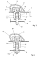
- the hollow profile 3 is composed of a threaded insert 6, a threaded plate 10, a clamping sleeve formed as an expansion element 7, a bolt 8 and a screw-threaded onto the bolt nut 14 with washer 14a.
- FIG. 4 the connection and the interaction of the screw 6 with the threaded plate 10 described.
- the screw insert 6 has in the longitudinal direction essentially two sections, namely a threaded section 21 with an external thread formed thereon and a further longitudinal section 22.
- the diameter of the longitudinal section 22 is as FIG. 4 can be seen, compared to the diameter in the threaded portion 21 radially expanded.
- the arrangement of the screw insert 6 is such that it passes through the opening in the roof skin 1 as well as through the essentially coaxial opening in the profile base 12 for this purpose.
- Diameter of the screw 6 on its longitudinal portion 22 is greater than the width of the opening in the profile base 12. In this way, the longitudinal section 22 sits with little play in the opening of the roof 1, but at the same time supports the screw 6 in the region of its stage 23rd from below against the profile base 12 from.
- the threaded plate 10 With the threaded portion 21 of the screw 6 in threaded connection 9 is the threaded plate 10. This is based with its underside from the inside of the profile base 12 from. Therefore, when the screw insert 6 is tightened with respect to the threaded plate 10, the surrounding area of the profile base 12 is clamped between the radially expanded longitudinal portion 22 of the screw insert 6 and the underside of the threaded plate 10. In order to tighten the threaded connection 9, the screw insert 6 is screwed into the non-rotatably secured threaded plate 10 and tightened sufficiently firmly. In order to avoid co-rotation of the threaded plate 10, this is secured against rotation in the hollow section 3 used. For this purpose, the threaded plate 10 is out of round designed in such a way that it is partially supported against the inner wall of an asymmetric cross-section having profile 3, and therefore it is not able to turn.
- FIG. 4 shows that the engagement surfaces 25 are located on the inner surfaces of a cavity 28 with square cross-section.
- the cavity 28 extends over a portion of the overall length of the threaded insert 6, whereas the other portion of the overall length is occupied by a cylindrical bore 29.
- the four-edged cavity 28 and the cylindrical bore 29 are aligned with each other and together form a continuous opening in the bush-shaped threaded insert 6.
- the central axis of the cylindrical bore 29 and the cavity 28 is coaxial with the longitudinal axis of the screw 6 total.
- the diameter D of the cylindrical bore 29 is larger than the transverse blade in the region of the square 28, so that in the transition from the cylindrical bore 29 into the square 28, a step 30 results.
- FIGS. 2 and 3 is in the cylindrical bore 29 of the screw 6 used as the expansion sleeve clamping element 7 inserted from below.
- the clamping element 7 passes through the elongated bolt 8.
- On this longitudinal portion of the bolt 8 is provided with a thread 33 on which the threaded nut 14 is screwed, with the threaded nut 14, possibly with the interposition of the washer 14 a, from below against the stable roof frame 5 is supported after completion of the assembly ( FIG. 3 ).
- the bolt 8 is axially movable with respect to the screw insert 6, but not rotatable.
- the bolt 8 is provided at its reaching into the square 28 of the threaded insert 6 end with a suitable anti-rotation, z. B. a square.
- the clamping element 7 has a sleeve-shaped or sleeve-shaped longitudinal section and, already outside of the screw insert 6, a radially expanded flange 35.
- this is designed as an expansion sleeve with individual, separated by longitudinal slots expansion segments.
- the outer side of the bolt 8 and the inner wall of the expansion sleeve 7 each have conical surfaces.
- FIG. 2 shows the initial state during assembly, in which state the expansion sleeve 7 is still loose in the cylindrical bore 29 of the screw 6 sits. Is now placed on the thread 33, the threaded nut 14 with the washer 14 a and tightened, first bolt 8 and expansion sleeve 7 are moved together down until the in the state FIG. 2 remaining free space F between the bottom of the flange 35 and the top of the roof frame 5 is zero. Only then does a further tightening of the threaded nut 14 leads to an axial relative movement between the pin 8 and the expansion sleeve 7, whereby the latter widens and frictionally presses against the cylindrical bore 29 of the threaded insert 6 from the inside. In this state, the hollow profile 3 is then permanently anchored to the roof 1 and the roof frame 5.
- FIGS. 5 and 6 a second embodiment of the arrangement is shown.
- key surfaces 25, for example, located in the region of the outer circumferential surface of the screw 6 key surfaces 25, for example, have a total of a square or hexagonal shape.
- a double-sided adhesive tape 40 located between the end face of the screw 6 and the top of the flange 35. This prevents that during pre-assembly after FIG. 5 , ie when passing through the unit through the openings provided in roof 1 and roof frame 5, the clamping element 7 and the bolt 8 fall out of the screw 6. Only by tightening the bolt 8 by means of the threaded nut 14 ( FIG. 6 ) dissolves the adhesive tape 40, which is then no longer needed.
Landscapes
- Engineering & Computer Science (AREA)
- Mechanical Engineering (AREA)
- Fittings On The Vehicle Exterior For Carrying Loads, And Devices For Holding Or Mounting Articles (AREA)
Applications Claiming Priority (1)
| Application Number | Priority Date | Filing Date | Title |
|---|---|---|---|
| DE102008017859.4A DE102008017859B4 (de) | 2008-04-09 | 2008-04-09 | Anordnung zur Befestigung eines Profils insbesondere eines Hohlprofils, an einem Fahrzeugdach |
Publications (3)
| Publication Number | Publication Date |
|---|---|
| EP2108545A2 true EP2108545A2 (fr) | 2009-10-14 |
| EP2108545A3 EP2108545A3 (fr) | 2010-03-10 |
| EP2108545B1 EP2108545B1 (fr) | 2011-05-04 |
Family
ID=40785562
Family Applications (1)
| Application Number | Title | Priority Date | Filing Date |
|---|---|---|---|
| EP09153058A Not-in-force EP2108545B1 (fr) | 2008-04-09 | 2009-02-18 | Agencement de fixation d'un profilé, notamment d'un profilé creux, sur un toit de véhicule |
Country Status (3)
| Country | Link |
|---|---|
| EP (1) | EP2108545B1 (fr) |
| DE (1) | DE102008017859B4 (fr) |
| ES (1) | ES2364694T3 (fr) |
Cited By (2)
| Publication number | Priority date | Publication date | Assignee | Title |
|---|---|---|---|---|
| WO2013060572A1 (fr) * | 2011-10-27 | 2013-05-02 | Böllhoff Verbindungstechnik GmbH | Élément de fixation à fonction de compensation des tolérances |
| US20150345528A1 (en) * | 2013-04-03 | 2015-12-03 | Ford Global Technologies, Llc | Adjustable Tower Stud Assembly |
Families Citing this family (6)
| Publication number | Priority date | Publication date | Assignee | Title |
|---|---|---|---|---|
| DE102009026245A1 (de) * | 2009-07-24 | 2011-01-27 | Jac Products Deutschland Gmbh | Vorrichtung zur Befestigung eines Anbauteils, z. B. einer Reling, an einer Fahrzeugkarosserie |
| DE202010009930U1 (de) * | 2010-07-01 | 2011-10-26 | Brose Fahrzeugteile Gmbh & Co. Kommanditgesellschaft, Hallstadt | Fensterheberbaugruppe |
| US8814014B2 (en) | 2012-05-10 | 2014-08-26 | Jac Products, Inc. | Device for mounting attachment externally supporting against body outer panel of vehicle body on body structure |
| US12391188B2 (en) | 2022-10-27 | 2025-08-19 | Honda Motor Co., Ltd. | Eye plate lifting feature with roof side applique |
| US12054101B2 (en) | 2022-10-27 | 2024-08-06 | Honda Motor Co., Ltd. | Roof top sensor module with internal bracket |
| US12208745B2 (en) | 2022-10-27 | 2025-01-28 | Honda Motor Co., Ltd. | Water intrusion prevention system for roof top module |
Citations (3)
| Publication number | Priority date | Publication date | Assignee | Title |
|---|---|---|---|---|
| DE2939671A1 (de) | 1979-09-29 | 1981-04-16 | Volkswagenwerk Ag, 3180 Wolfsburg | Anordnung zur befestigung eines aufbaus, insbesondere einer reling fuer einen dachgepaecktraeger, auf einem fahrzeug-dach |
| DE3121086C2 (fr) | 1981-05-27 | 1989-04-13 | Gebr. Happich Gmbh, 5600 Wuppertal, De | |
| EP0950569A1 (fr) | 1998-02-25 | 1999-10-20 | JAC Products Deutschland GmbH | Dispositif de fixation pour rail de toit pour véhicule |
Family Cites Families (5)
| Publication number | Priority date | Publication date | Assignee | Title |
|---|---|---|---|---|
| DE3736028C1 (en) * | 1987-10-24 | 1989-02-02 | Bayerische Motoren Werke Ag | Fastening device for a roofrack arranged on a vehicle roof |
| DE29804777U1 (de) * | 1998-03-17 | 1999-07-22 | fischerwerke Artur Fischer GmbH & Co. KG, 72178 Waldachtal | Vorrichtung zur Befestigung einer Dachreling auf einem Autodach |
| DE20019533U1 (de) * | 2000-11-17 | 2002-04-04 | Hagus C. Luchtenberg Gmbh & Co Kg, 42719 Solingen | Relingfuß |
| DE202004018079U1 (de) * | 2004-09-24 | 2005-01-20 | Hans Und Ottmar Binder Gmbh | Dachträgersystem für ein Fahrzeug und Fahrzeug mit einem Dachträgersystem |
| DE102005013451B3 (de) * | 2005-03-21 | 2006-10-19 | Sportrack Gmbh | Befestigungsvorrichtung |
-
2008
- 2008-04-09 DE DE102008017859.4A patent/DE102008017859B4/de not_active Expired - Fee Related
-
2009
- 2009-02-18 EP EP09153058A patent/EP2108545B1/fr not_active Not-in-force
- 2009-02-18 ES ES09153058T patent/ES2364694T3/es active Active
Patent Citations (3)
| Publication number | Priority date | Publication date | Assignee | Title |
|---|---|---|---|---|
| DE2939671A1 (de) | 1979-09-29 | 1981-04-16 | Volkswagenwerk Ag, 3180 Wolfsburg | Anordnung zur befestigung eines aufbaus, insbesondere einer reling fuer einen dachgepaecktraeger, auf einem fahrzeug-dach |
| DE3121086C2 (fr) | 1981-05-27 | 1989-04-13 | Gebr. Happich Gmbh, 5600 Wuppertal, De | |
| EP0950569A1 (fr) | 1998-02-25 | 1999-10-20 | JAC Products Deutschland GmbH | Dispositif de fixation pour rail de toit pour véhicule |
Cited By (5)
| Publication number | Priority date | Publication date | Assignee | Title |
|---|---|---|---|---|
| WO2013060572A1 (fr) * | 2011-10-27 | 2013-05-02 | Böllhoff Verbindungstechnik GmbH | Élément de fixation à fonction de compensation des tolérances |
| CN103747982A (zh) * | 2011-10-27 | 2014-04-23 | 伯尔霍夫连接技术有限公司 | 具有公差补偿功能的固定元件 |
| CN103747982B (zh) * | 2011-10-27 | 2016-05-04 | 伯尔霍夫连接技术有限公司 | 具有公差补偿功能的固定元件 |
| US20150345528A1 (en) * | 2013-04-03 | 2015-12-03 | Ford Global Technologies, Llc | Adjustable Tower Stud Assembly |
| US9726206B2 (en) * | 2013-04-03 | 2017-08-08 | Ford Global Technologies, Llc | Method of attaching an object to a panel with an adjustable tower stud assembly |
Also Published As
| Publication number | Publication date |
|---|---|
| EP2108545A3 (fr) | 2010-03-10 |
| ES2364694T3 (es) | 2011-09-12 |
| DE102008017859A1 (de) | 2009-10-15 |
| DE102008017859B4 (de) | 2020-09-17 |
| EP2108545B1 (fr) | 2011-05-04 |
Similar Documents
| Publication | Publication Date | Title |
|---|---|---|
| EP2108545B1 (fr) | Agencement de fixation d'un profilé, notamment d'un profilé creux, sur un toit de véhicule | |
| DE4033763C2 (de) | Vorrichtung zum Sichern einer in einer Öffnung in einer Verkleidung aufgenommenen Mutter | |
| EP2532568B1 (fr) | Dispositif de fixation d'un composant, par exemple d'une rambarde, sur une carrosserie de véhicule | |
| EP0226710B1 (fr) | Rail d'ancrage pour la technique du bâtiment | |
| EP2857699B1 (fr) | Douille taraudée à visser | |
| EP0678679A1 (fr) | Elément à montage par rivetage dans une pièce en tôle | |
| EP0307647A1 (fr) | Rondelle | |
| DE102013109036A1 (de) | Verfahren zum Verbinden von Bauteilen sowie Baugruppe | |
| DE102012221228A1 (de) | Toleranzausgleichsvorrichtung | |
| EP1794030B1 (fr) | Systeme de galerie pour vehicule | |
| EP2277742B1 (fr) | Dispositif de fixation d'une pièce, par exemple d'une rambarde, sur une carrosserie de véhicule | |
| DE102009024264A1 (de) | Befestigungselement, insbesondere Mutter | |
| EP2627915B1 (fr) | Dispositif d'ancrage destiné à fixer une pièce sur un élément de support | |
| AT413297B (de) | Befestigungsanordnung für einen beschlagsteil | |
| DE112004000952B4 (de) | Vormontierte Montageeinheit eines Blindniets sowie Verfahren zum Vernieten zweier Bauteile mit einem Blindniet | |
| DE102013105443A1 (de) | Befestigungselement | |
| DE102010060394A1 (de) | Vorrichtung zur Befestigung eines sich von außen gegenüber dem Karosserieaußenblech einer Fahrzeugkarosserie abstützenden Anbauteils | |
| DE102013002631B4 (de) | Bauteilverbindung für ein Anbauteil an einem Trägerteil | |
| DE202017105765U1 (de) | Befestigungsvorrichtung zur Befestigung von mindestens einem Bauteil | |
| EP0950569A1 (fr) | Dispositif de fixation pour rail de toit pour véhicule | |
| EP1612432B1 (fr) | Dispositif de fixation pour habillage et méthode de fixation | |
| EP0271648A1 (fr) | Système pour fixer des plaques de façade à une sous-construction | |
| WO2014048989A1 (fr) | Vis de montage destinée à la fixation de ferrures sur des profilés creux, kit de vis de montage et agencement constitué d'un profilé à plusieurs chambres et d'une vis de montage | |
| EP2803533B1 (fr) | Dispositif destiné à agencer une barre présentant un canal longitudinal sur un support | |
| AT409780B (de) | Vorrichtung für den zusammenbau von schaltafeln für betonkörper |
Legal Events
| Date | Code | Title | Description |
|---|---|---|---|
| PUAI | Public reference made under article 153(3) epc to a published international application that has entered the european phase |
Free format text: ORIGINAL CODE: 0009012 |
|
| AK | Designated contracting states |
Kind code of ref document: A2 Designated state(s): AT BE BG CH CY CZ DE DK EE ES FI FR GB GR HR HU IE IS IT LI LT LU LV MC MK MT NL NO PL PT RO SE SI SK TR |
|
| AX | Request for extension of the european patent |
Extension state: AL BA RS |
|
| PUAL | Search report despatched |
Free format text: ORIGINAL CODE: 0009013 |
|
| AK | Designated contracting states |
Kind code of ref document: A3 Designated state(s): AT BE BG CH CY CZ DE DK EE ES FI FR GB GR HR HU IE IS IT LI LT LU LV MC MK MT NL NO PL PT RO SE SI SK TR |
|
| AX | Request for extension of the european patent |
Extension state: AL BA RS |
|
| GRAP | Despatch of communication of intention to grant a patent |
Free format text: ORIGINAL CODE: EPIDOSNIGR1 |
|
| 17P | Request for examination filed |
Effective date: 20100727 |
|
| AKX | Designation fees paid |
Designated state(s): ES FR IT |
|
| RAP1 | Party data changed (applicant data changed or rights of an application transferred) |
Owner name: JAC PRODUCTS EUROPE GMBH |
|
| REG | Reference to a national code |
Ref country code: DE Ref legal event code: 8566 |
|
| GRAS | Grant fee paid |
Free format text: ORIGINAL CODE: EPIDOSNIGR3 |
|
| GRAA | (expected) grant |
Free format text: ORIGINAL CODE: 0009210 |
|
| AK | Designated contracting states |
Kind code of ref document: B1 Designated state(s): ES FR IT |
|
| REG | Reference to a national code |
Ref country code: ES Ref legal event code: FG2A Ref document number: 2364694 Country of ref document: ES Kind code of ref document: T3 Effective date: 20110912 |
|
| PLBE | No opposition filed within time limit |
Free format text: ORIGINAL CODE: 0009261 |
|
| STAA | Information on the status of an ep patent application or granted ep patent |
Free format text: STATUS: NO OPPOSITION FILED WITHIN TIME LIMIT |
|
| 26N | No opposition filed |
Effective date: 20120207 |
|
| REG | Reference to a national code |
Ref country code: FR Ref legal event code: PLFP Year of fee payment: 8 |
|
| REG | Reference to a national code |
Ref country code: FR Ref legal event code: PLFP Year of fee payment: 9 |
|
| REG | Reference to a national code |
Ref country code: FR Ref legal event code: PLFP Year of fee payment: 10 |
|
| PGFP | Annual fee paid to national office [announced via postgrant information from national office to epo] |
Ref country code: ES Payment date: 20190319 Year of fee payment: 11 Ref country code: IT Payment date: 20190222 Year of fee payment: 11 |
|
| PGFP | Annual fee paid to national office [announced via postgrant information from national office to epo] |
Ref country code: FR Payment date: 20190221 Year of fee payment: 11 |
|
| PG25 | Lapsed in a contracting state [announced via postgrant information from national office to epo] |
Ref country code: FR Free format text: LAPSE BECAUSE OF NON-PAYMENT OF DUE FEES Effective date: 20200229 |
|
| REG | Reference to a national code |
Ref country code: ES Ref legal event code: FD2A Effective date: 20210706 |
|
| PG25 | Lapsed in a contracting state [announced via postgrant information from national office to epo] |
Ref country code: ES Free format text: LAPSE BECAUSE OF NON-PAYMENT OF DUE FEES Effective date: 20200219 |
|
| PG25 | Lapsed in a contracting state [announced via postgrant information from national office to epo] |
Ref country code: IT Free format text: LAPSE BECAUSE OF NON-PAYMENT OF DUE FEES Effective date: 20200218 |