EP2108569A1 - Hintere plattenstruktur eines automobils - Google Patents
Hintere plattenstruktur eines automobils Download PDFInfo
- Publication number
- EP2108569A1 EP2108569A1 EP08738580A EP08738580A EP2108569A1 EP 2108569 A1 EP2108569 A1 EP 2108569A1 EP 08738580 A EP08738580 A EP 08738580A EP 08738580 A EP08738580 A EP 08738580A EP 2108569 A1 EP2108569 A1 EP 2108569A1
- Authority
- EP
- European Patent Office
- Prior art keywords
- rear panel
- tail light
- connecting piece
- opening
- triangular
- Prior art date
- Legal status (The legal status is an assumption and is not a legal conclusion. Google has not performed a legal analysis and makes no representation as to the accuracy of the status listed.)
- Granted
Links
Images


Classifications
-
- B—PERFORMING OPERATIONS; TRANSPORTING
- B60—VEHICLES IN GENERAL
- B60Q—ARRANGEMENT OF SIGNALLING OR LIGHTING DEVICES, THE MOUNTING OR SUPPORTING THEREOF OR CIRCUITS THEREFOR, FOR VEHICLES IN GENERAL
- B60Q1/00—Arrangement of optical signalling or lighting devices, the mounting or supporting thereof or circuits therefor
- B60Q1/26—Arrangement of optical signalling or lighting devices, the mounting or supporting thereof or circuits therefor the devices being primarily intended to indicate the vehicle, or parts thereof, or to give signals, to other traffic
- B60Q1/2619—Arrangement of optical signalling or lighting devices, the mounting or supporting thereof or circuits therefor the devices being primarily intended to indicate the vehicle, or parts thereof, or to give signals, to other traffic built in the vehicle body
- B60Q1/2638—Positioning the device housing by indexing means separate from the fastening means, e.g. pins, rails
Definitions
- the present invention relates to a rear panel arrangement for a motor vehicle, and in particular to a rear panel arrangement that includes an improved tail light mount.
- an opening is stamp formed in a rear panel outer or a rear fender panel in such dimensions and a configuration as to conform to the lens of the tail light, and the tail lamp lens is closely fitted into the opening so as to define a smooth outer profile of the rear part of the vehicle body in cooperation with the surrounding part of the panel member (of the rear panel outer or rear fender panel).
- the positioning of the lens of the tail light is accomplished by passing mounting reference holes through a flange that extends from the panel member into the opening, and fitting corresponding positioning projections formed in the lens into the mounting reference holes.
- the flanges through which the mounting reference holes are passed consist of cantilever pieces, and are therefore provided with a limited rigidity, they can readily deform during the stamp forming process and welding process. Therefore, some precaution is required to ensure the positional precision of the mounting reference holes, and this presents a challenge in ensuring the positional precision of the tail light lens at a high level.
- the flange When the opening is formed on each side part of the vehicle body in the shape of a V-shaped notch cut into the side panel member from a rear edge thereof, the flange typically extends from each of the upper side and lower side of the notch-shaped opening.
- the angle formed between the two sides of the notch tends to be narrowed or widened, and this causes the positions of the mounting references holes for a tail light to be pushed outward or inward, as the case may be, from the intended positions.
- the lens of a tail light When the lens of a tail light is mounted by using the mounting reference holes for the positioning of the lens under such a condition, the lens becomes raised above or recessed below the outer surface of the surrounding panel member, and this prevents the surface of the lens to be a part of the smooth outer contour of the rear part of the vehicle body.
- the tail light is prevented from being mounted in the proper position.
- a primary object of the present invention is to provide a rear panel arrangement for a motor vehicle that can prevent misalignment of a tail light caused by a deformation of a flange piece formed with a mounting reference hole owing to a lack of rigidity.
- a second object of the present invention is to provide a rear panel arrangement for a motor vehicle that ensures the surface of the lens of the tail light to be highly continuous with the contour of the rear part of the vehicle body.
- a third object of the present invention is to provide a rear panel arrangement for a motor vehicle that allows a high level of freedom in the design of the tail light.
- a rear panel arrangement for a motor vehicle comprising: a rear panel outer having a tail light mount opening formed therein; and a connecting piece extending across the tail light mount opening, the connecting piece being provided with a tail light mount reference hole for positioning a tail light.
- the connecting piece connects the upper and lower ends of the tail light mount opening, the opening is made resistant to deformation, and this ensures the positional precision of the tail light mount reference hole.
- the connecting piece is provided with a shaped cross section such as a L-shaped cross section, the rigidity of the connecting piece is improved, and the positional precision is further enhanced.
- the connecting piece is integrally stamp formed with the rear panel outer.
- the connecting piece is provided with a surface which is recessed with respect to a surrounding surface of the rear panel outer so that the tail light assembly may be mounted over the entire area of the tail light mount opening without unduly protruding from the surrounding contour of the rear side panel or rear panel outer.
- the tail light mount opening is provided with a V-shaped notch including an open rear side, and an upper side and lower side that merge at a forward end of the tail light mount opening, the connecting piece extending substantially vertically between the upper and lower sides thereof.
- the connecting piece can effectively prevent the angle formed between the upper and lower sides of the tail light mount opening from changing during the handling of the rear panel outer.
- the rear panel arrangement may further comprise a triangular panel inner which is attached to an inner side of the rear panel outer so as to at least partly close a triangular opening defined by a forward edge of the connecting piece and the upper and lower sides of the tail light mount opening, the triangular panel inner being welded to the connecting piece and parts of the rear panel outer adjoining the upper and lower sides of the triangular opening.
- a triangular panel inner that defmes a recess for receiving a tail light assembly can be formed as a separate component part so that the rear panel outer is not required to be formed with a recess as a drawing process at the time of stamping the rear panel outer, and this simplifies the stamping process of the rear panel outer.
- This triangular inner panel may be formed with an additional tail light mount reference hole so that the positional precision of the tail light may be improved even further.
- the triangular panel inner can be conveniently welded to the tab piece.
- Figure 1 generally illustrates a motor vehicle to which the rear panel arrangement of the present invention is applied.
- numeral 11 denotes a rear panel outer in a rear end of a side part of the vehicle body
- numeral 13 denotes a tailgate on the rear end of the vehicle body.
- the rear panel outer 11 is provided with a tail light mount opening 15 into which a lens 101 of a tail light is closely fitted.
- the surface of the lens 101 smoothly connects to that of the rear end portion of the vehicle body.
- the outer profile of the tail light defined by the lens 101 thereof has the shape of a V-shaped notch having a pointed end thereof facing forwardly of the vehicle body as seen from the side.
- the tail light mount opening 15 has the shape of a V-shaped notch having a pointed end thereof facing forwardly of the vehicle body as seen from the side.
- the tail light mount opening 15 includes an open rear side, and an upper side and lower side that merge at a forward end of the tail light mount opening 15.
- the rear panel outer 11 is provided with a bent piece or flange 17 extending substantially in an inboard direction and along each of the upper side and lower side of the tail light mount opening 15.
- the rear panel outer 11 is integrally provided with a connecting piece 19 that joins the upper side 15A and lower side 15B of the tail light mount opening 15 as an extension of the flanges 17.
- the connecting piece 19 extends substantially vertically between the upper and lower sides thereof.
- the connecting piece 19 includes a main part 19A as a continuous extension of the rear panel outer 11 and actually joins the upper and lower sides 15A and 15B.
- the outer surface of the main part 19A extends substantially in parallel with the surface of the surrounding part of the rear panel outer 11 but is recessed by a certain distance therefrom.
- the connecting piece 19 also includes a bent piece 19B that is bent in an inboard direction from the rear edge of the main body 19A in a perpendicular direction. Therefore, the connecting piece 19 is provided with an L-shaped cross section.
- the bent piece 19B is absent in each end portion of the connecting piece 19.
- the outer surface of the main part 19A may be flush with the surface of the surrounding part of the rear panel outer 11.
- the connecting piece 19 may be provided with a shaped cross section other than the L-shaped cross section.
- the main body 19A of the connecting piece 19 may have a pair of bent pieces both bent inboard on either side of the connecting piece 19.
- a tail light mount reference hole 21 is passed through the bent piece 19B of the connecting piece 19 by a stamp forming process. As this hole 21 is formed in the bent piece 19B extending in the lateral direction of the vehicle body, the hole 21 is passed in the fore-and-aft direction of the vehicle body.
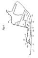
- the connecting piece 19 is provided centrally with respect to the fore-and-aft direction of the opening 15 so that the opening 15 includes not only the open-ended part that is behind the rear edge of the connecting piece 19 but also a closed triangular opening 15D that extends from the front edge (left edge as seen in Figure 3 ) of the connecting piece 19 to the pointed (forward) end of the notch-shaped portion of the opening 15.
- a rear pillar gutter 31 forming a rear panel inner by spot welding at points a to g.
- the rear pillar gutter 31 is placed so as to avoid the triangular opening 15D.
- the triangular opening 15D is closed from an inner side of the rear panel outer 11 by a triangular panel inner 33 which is formed as a member separate from the rear pillar gutter 31 and welded to points e, f and g of the connecting piece 19 and points I and h of the bonding tab pieces 23 and 25 by spot welding.
- the triangular panel inner 33 is a relatively small draw worked piece, and is provided with a flat surface 35 which is recessed and extends in parallel with the bent piece 19B of the connecting piece 19.
- Another tail light reference mount hole 37 is passed through the flat surface 35 by stamp forming, and this hole is also passed in the fore-and-aft direction of the vehicle body similarly as the aforementioned tail light reference mount hole 37.
- the lens 101 of the tail light is integrally formed with positioning projections 103 and 105, and one of the projections 103 is received by the reference hole 21 of the connecting piece 19 while the other projection 105 is received the reference hole 37 of the triangular panel inner 33.
- the lens 101 of the tail light is positioned with respect to the rear panel outer 11 at two positions, and this ensures that the surface of the lens 101 is continuously connected with the outer profile of the rear part of the vehicle body.
- the tail light mount opening 15 is prevented from deforming during the stamp forming process and welding process. Furthermore, because the connecting piece 19 is made of the main body 19A and bent piece 19B so as to define an L-shaped cross section, the connecting piece 19 is given with a high rigidity by itself, and the positional precision of the reference hole 21 formed in the connecting piece 19 can be ensured. As a result, the lens 101 of the tail light can be positioned at a high precision, and the outer surface of the lens of the tail light can be positively prevented from being raised or recessed from the outer surface of the rear panel outer 11.
- the triangular opening 15D extends from the forward edge of the connecting piece 19 to the pointed end 15C of the V-shaped notch, the triangular opening of the rear panel inner is not required to be formed by a drawing process, and the shape of the tail light mount opening 19 can be selected at will. As a result, a great freedom can be attained in the design of the outer profile of the lens of the tail light or the tail light design itself so that the tail light may be given with the shape of a V-shaped notch with the pointed end directed in the forward direction.
- the reference hole 37 of the triangular rear panel inner 33 can be at a high positional precision.
Landscapes
- Engineering & Computer Science (AREA)
- Mechanical Engineering (AREA)
- Lighting Device Outwards From Vehicle And Optical Signal (AREA)
- Body Structure For Vehicles (AREA)
- Automatic Cycles, And Cycles In General (AREA)
- Non-Portable Lighting Devices Or Systems Thereof (AREA)
- Motor Or Generator Cooling System (AREA)
Applications Claiming Priority (2)
| Application Number | Priority Date | Filing Date | Title |
|---|---|---|---|
| JP2007158366 | 2007-06-15 | ||
| PCT/JP2008/000974 WO2008152763A1 (ja) | 2007-06-15 | 2008-04-14 | 自動車のリアパネル構造 |
Publications (3)
| Publication Number | Publication Date |
|---|---|
| EP2108569A1 true EP2108569A1 (de) | 2009-10-14 |
| EP2108569A4 EP2108569A4 (de) | 2010-03-03 |
| EP2108569B1 EP2108569B1 (de) | 2011-01-12 |
Family
ID=40129378
Family Applications (1)
| Application Number | Title | Priority Date | Filing Date |
|---|---|---|---|
| EP08738580A Not-in-force EP2108569B1 (de) | 2007-06-15 | 2008-04-14 | Heckplattenanordnung für ein kraftfahrzeug |
Country Status (7)
| Country | Link |
|---|---|
| EP (1) | EP2108569B1 (de) |
| JP (1) | JP5185264B2 (de) |
| CN (1) | CN101626942B (de) |
| AT (1) | ATE495055T1 (de) |
| DE (1) | DE602008004439D1 (de) |
| TW (1) | TWI347280B (de) |
| WO (1) | WO2008152763A1 (de) |
Cited By (4)
| Publication number | Priority date | Publication date | Assignee | Title |
|---|---|---|---|---|
| EP3272584A1 (de) * | 2016-07-21 | 2018-01-24 | PSA Automobiles SA | Indexierungsvorrichtung einer beleuchtungs- und/oder signalisierungsvorrichtung eines kraftfahrzeugs |
| FR3057238A1 (fr) * | 2016-10-07 | 2018-04-13 | Peugeot Citroen Automobiles Sa | Ensemble de fixation d’un dispositif d’eclairage ou de signalisation dans un logement de reception de la caisse d’un vehicule automobile. |
| FR3102538A1 (fr) * | 2019-10-28 | 2021-04-30 | Psa Automobiles Sa | Ensemble de feu arrière de véhicule automobile |
| US11142119B1 (en) | 2020-03-31 | 2021-10-12 | Ford Global Technologies, Llc | Vehicle lighting assembly and installation method |
Families Citing this family (5)
| Publication number | Priority date | Publication date | Assignee | Title |
|---|---|---|---|---|
| FR2943307B1 (fr) * | 2009-03-17 | 2014-11-21 | Peugeot Citroen Automobiles Sa | Dispositif et procede pour fixer un feu arriere dans un logement de la caisse d'un vehicule automobile, feu arriere adapte pour etre fixe a un tel dispositif et vehicule equipe d'un tel arriere |
| DE102010027751B4 (de) * | 2010-04-14 | 2019-03-21 | Ford Global Technologies, Llc | Kraftfahrzeug |
| JP5608201B2 (ja) * | 2012-08-31 | 2014-10-15 | 本田技研工業株式会社 | 車両のリヤランプ取付構造 |
| JP5929939B2 (ja) * | 2014-02-04 | 2016-06-08 | トヨタ自動車株式会社 | 車両用リアランプ取付部のボデー構造 |
| DE102021109726B3 (de) * | 2021-04-19 | 2022-04-21 | Dr. Ing. H.C. F. Porsche Aktiengesellschaft | Verfahren zur Montage von Fahrzeugelementen eines Kraftfahrzeughecks |
Family Cites Families (10)
| Publication number | Priority date | Publication date | Assignee | Title |
|---|---|---|---|---|
| JPS6323231Y2 (de) * | 1980-04-17 | 1988-06-24 | ||
| JPS59106375A (ja) * | 1982-12-08 | 1984-06-20 | Nissan Motor Co Ltd | コ−ナリングランプ回りの車体構造 |
| JPH01167970U (de) * | 1988-05-10 | 1989-11-27 | ||
| JPH059234Y2 (de) * | 1988-11-22 | 1993-03-08 | ||
| JP2583373Y2 (ja) * | 1992-10-06 | 1998-10-22 | ダイハツ工業株式会社 | 自動車の車体後部の補強構造 |
| JPH10226360A (ja) * | 1997-02-17 | 1998-08-25 | Daihatsu Motor Co Ltd | 自動車の車体後部構造 |
| JP3539157B2 (ja) | 1997-10-08 | 2004-07-07 | 日産自動車株式会社 | リヤランプ周辺構造 |
| JP2000190775A (ja) * | 1998-12-25 | 2000-07-11 | Toyota Autom Loom Works Ltd | 車両用ランプの取付構造 |
| JP3981904B2 (ja) * | 1999-06-07 | 2007-09-26 | 関東自動車工業株式会社 | リヤコンビネーションランプの取付部ボディ構造 |
| KR100514480B1 (ko) * | 2003-09-01 | 2005-09-14 | 기아자동차주식회사 | 자동차용 헤드램프와 휀더간의 간극 유지 구조 |
-
2008
- 2008-04-14 AT AT08738580T patent/ATE495055T1/de not_active IP Right Cessation
- 2008-04-14 CN CN200880007191.7A patent/CN101626942B/zh not_active Expired - Fee Related
- 2008-04-14 WO PCT/JP2008/000974 patent/WO2008152763A1/ja not_active Ceased
- 2008-04-14 EP EP08738580A patent/EP2108569B1/de not_active Not-in-force
- 2008-04-14 JP JP2009519142A patent/JP5185264B2/ja not_active Expired - Fee Related
- 2008-04-14 DE DE602008004439T patent/DE602008004439D1/de active Active
- 2008-05-07 TW TW097116872A patent/TWI347280B/zh not_active IP Right Cessation
Cited By (5)
| Publication number | Priority date | Publication date | Assignee | Title |
|---|---|---|---|---|
| EP3272584A1 (de) * | 2016-07-21 | 2018-01-24 | PSA Automobiles SA | Indexierungsvorrichtung einer beleuchtungs- und/oder signalisierungsvorrichtung eines kraftfahrzeugs |
| FR3054179A1 (fr) * | 2016-07-21 | 2018-01-26 | Peugeot Citroen Automobiles Sa | Dispositif d’indexation d’un dispositif d’eclairage et/ou de signalisation lumineuse d’un vehicule automobile |
| FR3057238A1 (fr) * | 2016-10-07 | 2018-04-13 | Peugeot Citroen Automobiles Sa | Ensemble de fixation d’un dispositif d’eclairage ou de signalisation dans un logement de reception de la caisse d’un vehicule automobile. |
| FR3102538A1 (fr) * | 2019-10-28 | 2021-04-30 | Psa Automobiles Sa | Ensemble de feu arrière de véhicule automobile |
| US11142119B1 (en) | 2020-03-31 | 2021-10-12 | Ford Global Technologies, Llc | Vehicle lighting assembly and installation method |
Also Published As
| Publication number | Publication date |
|---|---|
| JPWO2008152763A1 (ja) | 2010-08-26 |
| TW200911595A (en) | 2009-03-16 |
| EP2108569A4 (de) | 2010-03-03 |
| TWI347280B (en) | 2011-08-21 |
| DE602008004439D1 (de) | 2011-02-24 |
| CN101626942B (zh) | 2012-04-04 |
| EP2108569B1 (de) | 2011-01-12 |
| CN101626942A (zh) | 2010-01-13 |
| ATE495055T1 (de) | 2011-01-15 |
| JP5185264B2 (ja) | 2013-04-17 |
| WO2008152763A1 (ja) | 2008-12-18 |
Similar Documents
| Publication | Publication Date | Title |
|---|---|---|
| EP2108569B1 (de) | Heckplattenanordnung für ein kraftfahrzeug | |
| US7841651B2 (en) | Vehicle front end assembly | |
| US7651158B2 (en) | Vehicle body structure | |
| US8567853B2 (en) | Vehicle body structure | |
| US10112653B2 (en) | Vehicle lower structure | |
| US8845009B2 (en) | Center pillar upper portion joining structure | |
| JP5873106B2 (ja) | 車両の意匠部品配置構造 | |
| JP4184577B2 (ja) | 車両用インストルメントパネルの取付構造 | |
| CN111108011A (zh) | 车门窗框构造 | |
| EP2923870B1 (de) | Verstärkungsstruktur für eine fahrzeugtür | |
| JP2010047183A (ja) | 車両前部の構造 | |
| US7168756B2 (en) | Vehicle front pillar construction | |
| CN111051101A (zh) | 车门窗框构造 | |
| EP1547908B1 (de) | Befestigungseinrichtung einer Lüfterzarge und Verfahren zur Befestigung der Lüfterzarge | |
| JP4990986B2 (ja) | テールライト構造 | |
| JP3981581B2 (ja) | 車輌用灯具の取付構造 | |
| CN104228728A (zh) | 后保险杠 | |
| KR100514246B1 (ko) | 자동차용 후드 인너 패널의 결합 구조 | |
| JP3865613B2 (ja) | 自動車のバンパ補強構造 | |
| JPH10218026A (ja) | 自動車の車体構造 | |
| JP2022048562A (ja) | ルーフライニングの取付構造 | |
| JP2009120072A (ja) | 車両用のリヤバンパ | |
| JP6853305B2 (ja) | 灯体取付構造 | |
| JP5315541B2 (ja) | 車両用インストルメントパネルの取付構造 | |
| JP2006040564A (ja) | ランプ用ハーネスの保護構造 |
Legal Events
| Date | Code | Title | Description |
|---|---|---|---|
| PUAI | Public reference made under article 153(3) epc to a published international application that has entered the european phase |
Free format text: ORIGINAL CODE: 0009012 |
|
| 17P | Request for examination filed |
Effective date: 20090806 |
|
| AK | Designated contracting states |
Kind code of ref document: A1 Designated state(s): AT BE BG CH CY CZ DE DK EE ES FI FR GB GR HR HU IE IS IT LI LT LU LV MC MT NL NO PL PT RO SE SI SK TR |
|
| A4 | Supplementary search report drawn up and despatched |
Effective date: 20100202 |
|
| RIC1 | Information provided on ipc code assigned before grant |
Ipc: B60Q 1/26 20060101AFI20100127BHEP Ipc: B62D 25/08 20060101ALI20100127BHEP |
|
| 17Q | First examination report despatched |
Effective date: 20100218 |
|
| GRAP | Despatch of communication of intention to grant a patent |
Free format text: ORIGINAL CODE: EPIDOSNIGR1 |
|
| RIC1 | Information provided on ipc code assigned before grant |
Ipc: B62D 25/08 20060101ALI20100630BHEP Ipc: B60Q 1/26 20060101AFI20100630BHEP |
|
| DAX | Request for extension of the european patent (deleted) | ||
| GRAS | Grant fee paid |
Free format text: ORIGINAL CODE: EPIDOSNIGR3 |
|
| GRAA | (expected) grant |
Free format text: ORIGINAL CODE: 0009210 |
|
| RTI1 | Title (correction) |
Free format text: REAR PANEL ARRANGEMENT FOR A MOTOR VEHICLE |
|
| AK | Designated contracting states |
Kind code of ref document: B1 Designated state(s): AT BE BG CH CY CZ DE DK EE ES FI FR GB GR HR HU IE IS IT LI LT LU LV MC MT NL NO PL PT RO SE SI SK TR |
|
| REG | Reference to a national code |
Ref country code: GB Ref legal event code: FG4D |
|
| REG | Reference to a national code |
Ref country code: CH Ref legal event code: EP |
|
| REG | Reference to a national code |
Ref country code: IE Ref legal event code: FG4D |
|
| REF | Corresponds to: |
Ref document number: 602008004439 Country of ref document: DE Date of ref document: 20110224 Kind code of ref document: P |
|
| REG | Reference to a national code |
Ref country code: DE Ref legal event code: R096 Ref document number: 602008004439 Country of ref document: DE Effective date: 20110224 |
|
| REG | Reference to a national code |
Ref country code: NL Ref legal event code: VDEP Effective date: 20110112 |
|
| LTIE | Lt: invalidation of european patent or patent extension |
Effective date: 20110112 |
|
| PG25 | Lapsed in a contracting state [announced via postgrant information from national office to epo] |
Ref country code: ES Free format text: LAPSE BECAUSE OF FAILURE TO SUBMIT A TRANSLATION OF THE DESCRIPTION OR TO PAY THE FEE WITHIN THE PRESCRIBED TIME-LIMIT Effective date: 20110423 Ref country code: PT Free format text: LAPSE BECAUSE OF FAILURE TO SUBMIT A TRANSLATION OF THE DESCRIPTION OR TO PAY THE FEE WITHIN THE PRESCRIBED TIME-LIMIT Effective date: 20110512 Ref country code: NO Free format text: LAPSE BECAUSE OF FAILURE TO SUBMIT A TRANSLATION OF THE DESCRIPTION OR TO PAY THE FEE WITHIN THE PRESCRIBED TIME-LIMIT Effective date: 20110412 Ref country code: SE Free format text: LAPSE BECAUSE OF FAILURE TO SUBMIT A TRANSLATION OF THE DESCRIPTION OR TO PAY THE FEE WITHIN THE PRESCRIBED TIME-LIMIT Effective date: 20110112 Ref country code: LV Free format text: LAPSE BECAUSE OF FAILURE TO SUBMIT A TRANSLATION OF THE DESCRIPTION OR TO PAY THE FEE WITHIN THE PRESCRIBED TIME-LIMIT Effective date: 20110112 Ref country code: IS Free format text: LAPSE BECAUSE OF FAILURE TO SUBMIT A TRANSLATION OF THE DESCRIPTION OR TO PAY THE FEE WITHIN THE PRESCRIBED TIME-LIMIT Effective date: 20110512 Ref country code: LT Free format text: LAPSE BECAUSE OF FAILURE TO SUBMIT A TRANSLATION OF THE DESCRIPTION OR TO PAY THE FEE WITHIN THE PRESCRIBED TIME-LIMIT Effective date: 20110112 Ref country code: HR Free format text: LAPSE BECAUSE OF FAILURE TO SUBMIT A TRANSLATION OF THE DESCRIPTION OR TO PAY THE FEE WITHIN THE PRESCRIBED TIME-LIMIT Effective date: 20110112 Ref country code: GR Free format text: LAPSE BECAUSE OF FAILURE TO SUBMIT A TRANSLATION OF THE DESCRIPTION OR TO PAY THE FEE WITHIN THE PRESCRIBED TIME-LIMIT Effective date: 20110413 |
|
| PG25 | Lapsed in a contracting state [announced via postgrant information from national office to epo] |
Ref country code: FI Free format text: LAPSE BECAUSE OF FAILURE TO SUBMIT A TRANSLATION OF THE DESCRIPTION OR TO PAY THE FEE WITHIN THE PRESCRIBED TIME-LIMIT Effective date: 20110112 Ref country code: PL Free format text: LAPSE BECAUSE OF FAILURE TO SUBMIT A TRANSLATION OF THE DESCRIPTION OR TO PAY THE FEE WITHIN THE PRESCRIBED TIME-LIMIT Effective date: 20110112 Ref country code: NL Free format text: LAPSE BECAUSE OF FAILURE TO SUBMIT A TRANSLATION OF THE DESCRIPTION OR TO PAY THE FEE WITHIN THE PRESCRIBED TIME-LIMIT Effective date: 20110112 Ref country code: BG Free format text: LAPSE BECAUSE OF FAILURE TO SUBMIT A TRANSLATION OF THE DESCRIPTION OR TO PAY THE FEE WITHIN THE PRESCRIBED TIME-LIMIT Effective date: 20110412 Ref country code: BE Free format text: LAPSE BECAUSE OF FAILURE TO SUBMIT A TRANSLATION OF THE DESCRIPTION OR TO PAY THE FEE WITHIN THE PRESCRIBED TIME-LIMIT Effective date: 20110112 Ref country code: CY Free format text: LAPSE BECAUSE OF FAILURE TO SUBMIT A TRANSLATION OF THE DESCRIPTION OR TO PAY THE FEE WITHIN THE PRESCRIBED TIME-LIMIT Effective date: 20110112 Ref country code: SI Free format text: LAPSE BECAUSE OF FAILURE TO SUBMIT A TRANSLATION OF THE DESCRIPTION OR TO PAY THE FEE WITHIN THE PRESCRIBED TIME-LIMIT Effective date: 20110112 Ref country code: AT Free format text: LAPSE BECAUSE OF FAILURE TO SUBMIT A TRANSLATION OF THE DESCRIPTION OR TO PAY THE FEE WITHIN THE PRESCRIBED TIME-LIMIT Effective date: 20110112 |
|
| PG25 | Lapsed in a contracting state [announced via postgrant information from national office to epo] |
Ref country code: EE Free format text: LAPSE BECAUSE OF FAILURE TO SUBMIT A TRANSLATION OF THE DESCRIPTION OR TO PAY THE FEE WITHIN THE PRESCRIBED TIME-LIMIT Effective date: 20110112 Ref country code: DK Free format text: LAPSE BECAUSE OF FAILURE TO SUBMIT A TRANSLATION OF THE DESCRIPTION OR TO PAY THE FEE WITHIN THE PRESCRIBED TIME-LIMIT Effective date: 20110112 |
|
| PLBE | No opposition filed within time limit |
Free format text: ORIGINAL CODE: 0009261 |
|
| STAA | Information on the status of an ep patent application or granted ep patent |
Free format text: STATUS: NO OPPOSITION FILED WITHIN TIME LIMIT |
|
| PG25 | Lapsed in a contracting state [announced via postgrant information from national office to epo] |
Ref country code: SK Free format text: LAPSE BECAUSE OF FAILURE TO SUBMIT A TRANSLATION OF THE DESCRIPTION OR TO PAY THE FEE WITHIN THE PRESCRIBED TIME-LIMIT Effective date: 20110112 Ref country code: RO Free format text: LAPSE BECAUSE OF FAILURE TO SUBMIT A TRANSLATION OF THE DESCRIPTION OR TO PAY THE FEE WITHIN THE PRESCRIBED TIME-LIMIT Effective date: 20110112 Ref country code: MC Free format text: LAPSE BECAUSE OF NON-PAYMENT OF DUE FEES Effective date: 20110430 Ref country code: CZ Free format text: LAPSE BECAUSE OF FAILURE TO SUBMIT A TRANSLATION OF THE DESCRIPTION OR TO PAY THE FEE WITHIN THE PRESCRIBED TIME-LIMIT Effective date: 20110112 |
|
| 26N | No opposition filed |
Effective date: 20111013 |
|
| PG25 | Lapsed in a contracting state [announced via postgrant information from national office to epo] |
Ref country code: IT Free format text: LAPSE BECAUSE OF FAILURE TO SUBMIT A TRANSLATION OF THE DESCRIPTION OR TO PAY THE FEE WITHIN THE PRESCRIBED TIME-LIMIT Effective date: 20110112 Ref country code: MT Free format text: LAPSE BECAUSE OF FAILURE TO SUBMIT A TRANSLATION OF THE DESCRIPTION OR TO PAY THE FEE WITHIN THE PRESCRIBED TIME-LIMIT Effective date: 20110112 |
|
| REG | Reference to a national code |
Ref country code: IE Ref legal event code: MM4A |
|
| REG | Reference to a national code |
Ref country code: DE Ref legal event code: R097 Ref document number: 602008004439 Country of ref document: DE Effective date: 20111013 |
|
| PG25 | Lapsed in a contracting state [announced via postgrant information from national office to epo] |
Ref country code: IE Free format text: LAPSE BECAUSE OF NON-PAYMENT OF DUE FEES Effective date: 20110414 |
|
| REG | Reference to a national code |
Ref country code: CH Ref legal event code: PL |
|
| GBPC | Gb: european patent ceased through non-payment of renewal fee |
Effective date: 20120414 |
|
| PG25 | Lapsed in a contracting state [announced via postgrant information from national office to epo] |
Ref country code: CH Free format text: LAPSE BECAUSE OF NON-PAYMENT OF DUE FEES Effective date: 20120430 Ref country code: LI Free format text: LAPSE BECAUSE OF NON-PAYMENT OF DUE FEES Effective date: 20120430 Ref country code: GB Free format text: LAPSE BECAUSE OF NON-PAYMENT OF DUE FEES Effective date: 20120414 |
|
| PG25 | Lapsed in a contracting state [announced via postgrant information from national office to epo] |
Ref country code: LU Free format text: LAPSE BECAUSE OF NON-PAYMENT OF DUE FEES Effective date: 20110414 |
|
| PGFP | Annual fee paid to national office [announced via postgrant information from national office to epo] |
Ref country code: FR Payment date: 20130625 Year of fee payment: 6 |
|
| PG25 | Lapsed in a contracting state [announced via postgrant information from national office to epo] |
Ref country code: TR Free format text: LAPSE BECAUSE OF FAILURE TO SUBMIT A TRANSLATION OF THE DESCRIPTION OR TO PAY THE FEE WITHIN THE PRESCRIBED TIME-LIMIT Effective date: 20110112 |
|
| PG25 | Lapsed in a contracting state [announced via postgrant information from national office to epo] |
Ref country code: HU Free format text: LAPSE BECAUSE OF FAILURE TO SUBMIT A TRANSLATION OF THE DESCRIPTION OR TO PAY THE FEE WITHIN THE PRESCRIBED TIME-LIMIT Effective date: 20110112 |
|
| REG | Reference to a national code |
Ref country code: FR Ref legal event code: ST Effective date: 20141231 |
|
| REG | Reference to a national code |
Ref country code: DE Ref legal event code: R084 Ref document number: 602008004439 Country of ref document: DE |
|
| PG25 | Lapsed in a contracting state [announced via postgrant information from national office to epo] |
Ref country code: FR Free format text: LAPSE BECAUSE OF NON-PAYMENT OF DUE FEES Effective date: 20140430 |
|
| REG | Reference to a national code |
Ref country code: DE Ref legal event code: R084 Ref document number: 602008004439 Country of ref document: DE Effective date: 20150210 |
|
| PGFP | Annual fee paid to national office [announced via postgrant information from national office to epo] |
Ref country code: DE Payment date: 20170411 Year of fee payment: 10 |
|
| REG | Reference to a national code |
Ref country code: DE Ref legal event code: R119 Ref document number: 602008004439 Country of ref document: DE |
|
| PG25 | Lapsed in a contracting state [announced via postgrant information from national office to epo] |
Ref country code: DE Free format text: LAPSE BECAUSE OF NON-PAYMENT OF DUE FEES Effective date: 20181101 |