EP2108810A2 - Kraftstoffeinspritzspitze - Google Patents
Kraftstoffeinspritzspitze Download PDFInfo
- Publication number
- EP2108810A2 EP2108810A2 EP09156698A EP09156698A EP2108810A2 EP 2108810 A2 EP2108810 A2 EP 2108810A2 EP 09156698 A EP09156698 A EP 09156698A EP 09156698 A EP09156698 A EP 09156698A EP 2108810 A2 EP2108810 A2 EP 2108810A2
- Authority
- EP
- European Patent Office
- Prior art keywords
- fuel
- holes
- valve
- injection
- diameter
- Prior art date
- Legal status (The legal status is an assumption and is not a legal conclusion. Google has not performed a legal analysis and makes no representation as to the accuracy of the status listed.)
- Withdrawn
Links
Images


Classifications
-
- F—MECHANICAL ENGINEERING; LIGHTING; HEATING; WEAPONS; BLASTING
- F02—COMBUSTION ENGINES; HOT-GAS OR COMBUSTION-PRODUCT ENGINE PLANTS
- F02M—SUPPLYING COMBUSTION ENGINES IN GENERAL WITH COMBUSTIBLE MIXTURES OR CONSTITUENTS THEREOF
- F02M61/00—Fuel-injectors not provided for in groups F02M39/00 - F02M57/00 or F02M67/00
- F02M61/16—Details not provided for in, or of interest apart from, the apparatus of groups F02M61/02 - F02M61/14
- F02M61/162—Means to impart a whirling motion to fuel upstream or near discharging orifices
-
- F—MECHANICAL ENGINEERING; LIGHTING; HEATING; WEAPONS; BLASTING
- F02—COMBUSTION ENGINES; HOT-GAS OR COMBUSTION-PRODUCT ENGINE PLANTS
- F02M—SUPPLYING COMBUSTION ENGINES IN GENERAL WITH COMBUSTIBLE MIXTURES OR CONSTITUENTS THEREOF
- F02M61/00—Fuel-injectors not provided for in groups F02M39/00 - F02M57/00 or F02M67/00
- F02M61/16—Details not provided for in, or of interest apart from, the apparatus of groups F02M61/02 - F02M61/14
- F02M61/18—Injection nozzles, e.g. having valve seats; Details of valve member seated ends, not otherwise provided for
- F02M61/1806—Injection nozzles, e.g. having valve seats; Details of valve member seated ends, not otherwise provided for characterised by the arrangement of discharge orifices, e.g. orientation or size
-
- F—MECHANICAL ENGINEERING; LIGHTING; HEATING; WEAPONS; BLASTING
- F02—COMBUSTION ENGINES; HOT-GAS OR COMBUSTION-PRODUCT ENGINE PLANTS
- F02M—SUPPLYING COMBUSTION ENGINES IN GENERAL WITH COMBUSTIBLE MIXTURES OR CONSTITUENTS THEREOF
- F02M61/00—Fuel-injectors not provided for in groups F02M39/00 - F02M57/00 or F02M67/00
- F02M61/16—Details not provided for in, or of interest apart from, the apparatus of groups F02M61/02 - F02M61/14
- F02M61/18—Injection nozzles, e.g. having valve seats; Details of valve member seated ends, not otherwise provided for
- F02M61/188—Spherical or partly spherical shaped valve member ends
-
- F—MECHANICAL ENGINEERING; LIGHTING; HEATING; WEAPONS; BLASTING
- F02—COMBUSTION ENGINES; HOT-GAS OR COMBUSTION-PRODUCT ENGINE PLANTS
- F02B—INTERNAL-COMBUSTION PISTON ENGINES; COMBUSTION ENGINES IN GENERAL
- F02B75/00—Other engines
- F02B75/12—Other methods of operation
- F02B2075/125—Direct injection in the combustion chamber for spark ignition engines, i.e. not in pre-combustion chamber
-
- Y—GENERAL TAGGING OF NEW TECHNOLOGICAL DEVELOPMENTS; GENERAL TAGGING OF CROSS-SECTIONAL TECHNOLOGIES SPANNING OVER SEVERAL SECTIONS OF THE IPC; TECHNICAL SUBJECTS COVERED BY FORMER USPC CROSS-REFERENCE ART COLLECTIONS [XRACs] AND DIGESTS
- Y02—TECHNOLOGIES OR APPLICATIONS FOR MITIGATION OR ADAPTATION AGAINST CLIMATE CHANGE
- Y02T—CLIMATE CHANGE MITIGATION TECHNOLOGIES RELATED TO TRANSPORTATION
- Y02T10/00—Road transport of goods or passengers
- Y02T10/10—Internal combustion engine [ICE] based vehicles
- Y02T10/12—Improving ICE efficiencies
Definitions
- the present invention relates to fuel injection systems of internal combustion engines for direct injection of fuel; more particularly, to fuel injectors for gasoline direct injection; and most particularly, to an improved injection tip and a method for reducing flow variations and impact force in the flow area between the ball and the seat of an injection valve.
- Fuel injected internal combustion engines are well known. Fuel injection arrangements may be divided generally into multi-port fuel injection (MPFI), wherein fuel is injected into a runner of an air intake manifold ahead of a cylinder intake valve, and gasoline direct injection (GDI), wherein fuel is injected directly into the combustion chamber of an engine cylinder, typically during or at the end of the compression stroke of the piston.
- MPFI multi-port fuel injection
- GDI gasoline direct injection
- GDI gasoline direct injection
- the injection tip of the fuel injector extends into the combustion chamber of the cylinder and includes director holes for dispersing and directing fuel injected from the injection valve.
- a typical fuel injection valve includes a beveled circular seat and a reciprocably-actuated ball that seals against the seat in a circular sealing line.
- injectors of gasoline direct injection engines provide potential for emission reduction as well as improvement in fuel economy and are, therefore, envisaged as next generation of fuel metering devices.
- the configuration and positioning of the director holes with respect to the injection valve ball and valve seat are crucial elements in the most fuel efficient distribution of fuel into the combustion chamber.
- the injector fuel flow path is important to achieve good performance of GDI injectors. Location and orientation of inflow holes that supply fuel to the valve area, large clearance between valve ball and the guide bore, as well as size, location, and orientation of the director holes are important to achieve adequate performance in fuel spray quality and targeting from the injector.
- inflow holes are used to feed fuel in the ball and seat area. These inflow holes are perpendicular to the ball surface.
- a known problem in prior art fuel injectors is that the ball is typically moved from the center to negotiate the guide bore when the injector is energized and the flow region around the ball becomes asymmetric. This results in flow variations downstream at the inlet side of the director holes. An asymmetric velocity profile at the inlet side of director holes is created due to the offset of the ball. This may result in spray skewness.
- the relative position of director flow holes with respect to the inflow holes is also important as the director holes away from the flow holes may stave resulting in flow skewness.
- a simple method to control this flow variation is to have very tight tolerances between the ball and the guide bore that limit the ball movement.
- very tight tolerances add cost to the engineering process, increase the risk of the ball getting stuck in the guide bore, and may also result in premature wear in the ball guide area.
- the fuel flow stream emanating from flow holes directly impinges on the ball surface since the inflow holes are positioned perpendicular to the ball surface, which may cause erosion of carbide particles from the ball surface.
- the loose carbide particles Once the loose carbide particles are taken away by this erosion process, they may act as abrasive particles helping fast removal of material from the ball and seat interface.
- the ball surface quality may be significantly reduced due to the wear out process and may finally result in fuel leakage through the sealing area between the valve seat and the ball.
- the high wear in the seat area may be aggravated with the use of corrosive fuel such as ethanol blended fuel, for example E10, E22, and E85.
- a fuel injector tip for a direct-injection fuel system in accordance with the invention includes tangential inflow holes that are used to feed fuel in the ball and seat area of a fuel injection valve.
- the fuel flow enters the flow area between the ball and the seat tangentially causing a swirling fluid motion that reduces the flow variations at the inlet side of the director holes and enabling a desirable larger clearance between the ball and the guide bore of the ball compared to prior art injector valves.
- the swirling motion of the fuel further assists in reducing the effect of a large velocity that is observed in the prior art due to the asymmetric nature of the flow area.
- the impact force on the ball surface is reduced compared to prior art perpendicular inflow holes. This may lower the erosion process at the ball and seat interface.
- a prior art injection tip 10 of a prior art direct-injection fuel injector includes an injection valve 12 having a beveled circular valve seat 14 and a reciprocably-actuated valve ball 16, a guide bore 18, four perpendicular inflow holes 20, and a plurality of director holes 22.
- Valve seat 14 is adapted to be sealingly welded into a body 28 of injection tip 10.
- Valve ball 16 seals against seat 14 in a circular sealing line.
- Guide bore 18 guides the axial movement of ball 16.
- Controllably varying the position of valve ball 16 with respect to valve seat 14 varies the flow of fuel across valve seat 14.
- Inflow holes 20 are positioned perpendicular to the surface of ball 16 and feed fuel into a flow area 29 between ball 16 and seat 14.
- Director holes 22 are in fluid communication with the flow area 29 between ball 16 and seat 14 and are inclined at different angles to provide a required spray target.
- the fuel jet emanating from inflow holes 20 impinges directly on the surface of ball 16, which may cause erosion on the surface of ball 16.
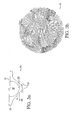
- the fuel jet emanating from inflow holes 20 also may move the ball from the center of guide bore 18. Accordingly, the flow area 29 around ball 16 may become asymmetric, which results in flow variations on the inlet side of director holes 22, as illustrated in the velocity vector plot 24 in FIG. 3b .
- Velocity vector plot 24 is taken along sectional plane 26 shown in FIG. 3a .
- Velocity vector plot 24 shows an asymmetric velocity profile at the inlet side of director holes 22 that is created by the offset of ball 16. Such flow variations may result in spray skewness, where director holes 22 away from flow holes 20 may starve. Referring to FIGS.
- a first injection tip 30 of a direct-injection injector in accordance with a first embodiment of the invention includes four tangential inflow holes 40.
- Injector tip 30 further includes an injection valve 32 having a beveled circular valve seat 34 and a reciprocably-actuated valve ball 36, a guide bore 38, a plurality of director holes 42 having a diameter 424, and a body 48 as known in the prior art and as described above for prior art injection tip 10 ( FIGS. 1-3 ).
- Inflow holes 40 have a diameter 402 and inflow openings 404 and are positioned tangential to valve seat 34 and to the surface of ball 36. Diameter 402 may be, for example, about 0.55 mm. Inflow openings 404 tangentially face valve ball 36 and are positioned preferably at equal distance from each other. More or less than the four tangential inlet holes 40 shown in FIG. 4 may be used. An even number of tangential inflow holes 40 may be used. Tangential inflow holes 40 may be positioned evenly around a circumference of valve ball 36 providing fuel flow to parallel tangents of ball 36 as shown in FIG. 4 .
- Inflow holes 40 feed fuel into a flow area 44 between ball 36 and seat 34 when ball 36 is lifted from seat 34.
- the fuel stream coming through inflow holes 40 enters flow area 44 tangentially thereby causing a swirling motion 46 of the fuel in flow area 44 as shown in FIG. 5b , a cross-sectional view along a first sectional plane 52 shown in FIG. 5a .
- the swirling motion 46 reduces the impact of the asymmetric nature of flow area 44 due to an offset position of ball 36 in seat 34.
- FIG. 5c a velocity vector plot 50 taken along a second sectional plane 54 ( FIG.
- the swirling motion 46 of the fuel is sufficient for reducing the flow variations in flow area 44 at the inlet side 422 of director holes 42 compared to the prior art. Accordingly, tangential inflow holes 40 minimize the flow variations in flow area 44.
- a guide bore to ball clearance 56, which is the difference between the diameter of guide bore 38 and the diameter of valve ball 36, of up to about 8 ⁇ m may be acceptable without increasing the flow variations.
- the swirling motion 46 of the fuel caused by tangential inflow holes 40 may further reduce flow variations due to the relative position of director holes 42 with respect to inflow holes 40.
- Velocity vector plot 50 shows a symmetric velocity profile of the fuel flow at the inlet side 422 of director holes 42. Even though ball 36 is offset, the velocity profile is symmetric and the flow variations are reduced utilizing tangential inflow holes 40 in accordance with the invention compared to prior art injection tip 10 having perpendicular inflow holes 20, as can be seen by comparing velocity vector plot 50 ( FIG. 5c ) in accordance with the invention with prior art velocity vector plot 24 ( FIG. 3b ).
- a reduced impact force in accordance with the invention may lower the erosion process on the surface of ball 36 and at the ball 36 and seat 34 interface significantly compared to prior art injection tip 10 shown in FIG. 1 .
- While the utilization of tangential inflow holes 40 in first injection tip 30 may reduce the flow variations on the inlet side 422 of director holes 42, the mass flow rate through injection valve 32 may also decrease.
- the reduction of mass flow rate can be compensated, for example, by using director holes having a larger diameter than director holes 42 or by using tangential inflow holes that have a larger diameter than inflow holes 40. It might further be possible to increase the number of tangential inflow holes 40 or director holes 42 to increase the mass flow rate through valve 32 without increasing the flow variations on the inlet side 422 of director holes 42.
- a second injection tip 60 of a direct-injection injector in accordance with a second embodiment of the invention includes four inflow holes 62, each having a diameter 622, and a plurality of director holes 64, each having a diameter 642.
- the diameter 622 of inflow holes 62 may be the same as diameter 402 of inflow holes 40 shown in FIG. 4 .
- the diameter 642 of the director holes 64 is larger than the diameter 424 of director holes 42 shown in FIG. 1 .
- Diameter 642 may be, for example, about 175 ⁇ m compared to about 165 ⁇ m of diameter 424.
- Increasing the size of director holes 64 ( FIG. 6 ) compared to the size of inflow holes 42 ( FIG. 4 ) increases the mass flow rate through injection valve 32 while maintaining the reduced flow variations between valve ball 36 and valve seat 34 on the inlet side of director holes 64.
- a third injection tip 70 in accordance with a third embodiment of the invention includes four inflow holes 72, each having a diameter 722, and a plurality of director holes 74, each having a diameter 742.
- the diameter 722 of inflow holes 72 is larger than the diameter 402 of inflow holes 40 shown in FIG. 4 .
- the diameter 742 of the director holes 74 may be the same as the diameter 424 of director holes 42 shown in FIG. 1 .
- Diameter 722 may be, for example, about 0.65 mm compared to about 0.55 mm of diameter 402.
- Increasing the size of director holes 74 ( FIG. 7 ) compared to the size of inflow holes 42 ( FIG. 4 ) increases the mass flow rate through injection valve 32 while maintaining the reduced flow variations between valve ball 36 and valve seat 34 on the inlet side of director holes 64.
- the increase in mass flow rate may be less for an increased diameter 722 of inflow holes 72 ( FIG. 7 ) than for an increased diameter 642 of director holes 64 ( FIG.6 ).
- FIGS. 6 and 7 show a change in only one parameter, the size of director holes 64 or the size of inflow holes 72, respectively, it may be possible to increase both parameters, the size of director holes 64 or the size of inflow holes 72, at the same time to achieve a higher mass flow rate while maintaining low flow variations.
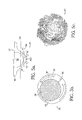
- a fourth injection tip 80 illustrated in FIGS. 8 and 9 includes only two tangential inflow holes 82.
- Inflow holes 82 are positioned such that the fuel stream coming through inflow holes 82 enters flow area 44 tangentially at opposite tangents of valve ball 36.
- the inflowing fuel causes a swirling motion of the fuel similar to the swirling motion 46 in flow area 44 as shown in FIG. 5b .
- a velocity vector plot 90 illustrated in FIG. 9b taken along a sectional plane 92 shown in FIG. 9a demonstrates that utilization of only two tangential inflow holes 82 also results in a symmetric velocity profile and that, thus, a reduction in flow variation compared to the prior art ( FIG. 3b ) can be achieved with only two tangential inflow holes 90. It is obvious from the velocity vector field shown in velocity vector plot 90 that design of the fourth injection tip 80 generates sufficient swirl to overcome the effect of ball valve 36 offset and rotation of director holes 42. To increase the mass flow rate through valve 32 in the fourth injection tip 80, the size of the injector holes can be increased as shown in Fig. 6 and/or the size of the two tangential inflow holes can be increased similar to inflow holes 74 shown in Fig. 7 .
- injection tips 30, 60, 70, and 80 in accordance with preferred embodiments of the invention, beneficially provide tangential inflow holes that enable a fuel stream to enter the gap between ball 36 and seat 36 of injection valve 32 tangentially creating a swirling motion.
- the swirling motion reduces the flow variations on the inlet side 422 of director holes 42 compared to prior art.
- the impact force of the inflowing fuel stream on the surface of ball 36 is reduced compared to the prior art, since in accordance with the invention the fuel stream acts tangentially on the surface of ball 36.
- injection tips 30, 60, 70, and 80 have been described to include four or two tangential inflow holes, any number of tangential inflow holes may be used in accordance with a specific application.
Landscapes
- Engineering & Computer Science (AREA)
- Chemical & Material Sciences (AREA)
- Combustion & Propulsion (AREA)
- Mechanical Engineering (AREA)
- General Engineering & Computer Science (AREA)
- Fuel-Injection Apparatus (AREA)
Applications Claiming Priority (1)
| Application Number | Priority Date | Filing Date | Title |
|---|---|---|---|
| US12/082,333 US20090255998A1 (en) | 2008-04-10 | 2008-04-10 | Fuel injection tip |
Publications (2)
| Publication Number | Publication Date |
|---|---|
| EP2108810A2 true EP2108810A2 (de) | 2009-10-14 |
| EP2108810A3 EP2108810A3 (de) | 2009-11-11 |
Family
ID=40793361
Family Applications (1)
| Application Number | Title | Priority Date | Filing Date |
|---|---|---|---|
| EP09156698A Withdrawn EP2108810A3 (de) | 2008-04-10 | 2009-03-30 | Kraftstoffeinspritzspitze |
Country Status (2)
| Country | Link |
|---|---|
| US (1) | US20090255998A1 (de) |
| EP (1) | EP2108810A3 (de) |
Cited By (3)
| Publication number | Priority date | Publication date | Assignee | Title |
|---|---|---|---|---|
| WO2011082916A1 (de) * | 2010-01-08 | 2011-07-14 | Robert Bosch Gmbh | Brennstoffeinspritzventil |
| US10077750B2 (en) | 2016-01-20 | 2018-09-18 | Ford Global Technologies, Llc | Method for operating a direct-injection internal combustion engine, and applied-ignition internal combustion engine for carrying out such a method |
| WO2019016201A1 (en) * | 2017-07-18 | 2019-01-24 | Continental Automotive Gmbh | SEAT BODY FOR A FLUID INJECTION VALVE AND FLUID INJECTION VALVE |
Families Citing this family (9)
| Publication number | Priority date | Publication date | Assignee | Title |
|---|---|---|---|---|
| US9909549B2 (en) * | 2014-10-01 | 2018-03-06 | National Technology & Engineering Solutions Of Sandia, Llc | Ducted fuel injection |
| JP6460802B2 (ja) * | 2015-01-09 | 2019-01-30 | 株式会社エンプラス | 燃料噴射装置用ノズルプレート |
| US10138855B2 (en) * | 2015-07-01 | 2018-11-27 | National Technology & Engineering Solutions Of Sandia, Llc | Ducted fuel injection with ignition assist |
| US10161626B2 (en) * | 2015-07-01 | 2018-12-25 | National Technology & Engineering Solutions Of Sandia, Llc | Ducted fuel injection |
| WO2017123755A1 (en) * | 2016-01-13 | 2017-07-20 | Sandia Corporation | Ducted fuel injection |
| US10801395B1 (en) | 2016-11-29 | 2020-10-13 | National Technology & Engineering Solutions Of Sandia, Llc | Ducted fuel injection |
| US10711752B2 (en) * | 2017-08-31 | 2020-07-14 | Caterpillar Inc. | Fuel injector assembly having duct structure |
| JP2022065542A (ja) * | 2020-10-15 | 2022-04-27 | 株式会社 Acr | 液体噴射ノズル |
| CN113339160B (zh) * | 2021-07-06 | 2022-07-05 | 西安航天动力研究所 | 液氧甲烷推力室喷注器 |
Family Cites Families (6)
| Publication number | Priority date | Publication date | Assignee | Title |
|---|---|---|---|---|
| JPH10281039A (ja) * | 1997-04-02 | 1998-10-20 | Hitachi Ltd | 燃料噴射装置とその制御方法 |
| JP3734924B2 (ja) * | 1997-06-02 | 2006-01-11 | 株式会社日立製作所 | エンジンの燃料噴射弁 |
| JP4032690B2 (ja) * | 2001-10-09 | 2008-01-16 | 株式会社日立製作所 | 筒内噴射ガソリンエンジン |
| JP2004036554A (ja) * | 2002-07-05 | 2004-02-05 | Hitachi Ltd | 燃料噴射装置,内燃機関及び燃料噴射装置の制御方法 |
| JP4244745B2 (ja) * | 2003-08-07 | 2009-03-25 | 日産自動車株式会社 | 筒内直噴式ガソリン機関 |
| JP4790441B2 (ja) * | 2006-02-17 | 2011-10-12 | 日立オートモティブシステムズ株式会社 | 電磁燃料噴射弁及びその組立て方法 |
-
2008
- 2008-04-10 US US12/082,333 patent/US20090255998A1/en not_active Abandoned
-
2009
- 2009-03-30 EP EP09156698A patent/EP2108810A3/de not_active Withdrawn
Cited By (5)
| Publication number | Priority date | Publication date | Assignee | Title |
|---|---|---|---|---|
| WO2011082916A1 (de) * | 2010-01-08 | 2011-07-14 | Robert Bosch Gmbh | Brennstoffeinspritzventil |
| CN102713245A (zh) * | 2010-01-08 | 2012-10-03 | 罗伯特·博世有限公司 | 燃料喷射阀 |
| US9133803B2 (en) | 2010-01-08 | 2015-09-15 | Robert Bosch Gmbh | Fuel injector having a plurality of flow-through regions |
| US10077750B2 (en) | 2016-01-20 | 2018-09-18 | Ford Global Technologies, Llc | Method for operating a direct-injection internal combustion engine, and applied-ignition internal combustion engine for carrying out such a method |
| WO2019016201A1 (en) * | 2017-07-18 | 2019-01-24 | Continental Automotive Gmbh | SEAT BODY FOR A FLUID INJECTION VALVE AND FLUID INJECTION VALVE |
Also Published As
| Publication number | Publication date |
|---|---|
| US20090255998A1 (en) | 2009-10-15 |
| EP2108810A3 (de) | 2009-11-11 |
Similar Documents
| Publication | Publication Date | Title |
|---|---|---|
| EP2108810A2 (de) | Kraftstoffeinspritzspitze | |
| US6883491B2 (en) | Fuel injection system | |
| EP2302197B1 (de) | Brennstoffeinspritzventil und brennstoffeinspritzvorrichtung | |
| JP5668984B2 (ja) | 燃料噴射装置 | |
| US9562503B2 (en) | Fuel injection nozzle | |
| US20120325922A1 (en) | Method of generating spray by fluid injection valve, fluid injection valve, and spray generation apparatus | |
| US20130092123A1 (en) | Combustion system for an engine having multiple fuel spray induced vortices | |
| US7383812B2 (en) | Fuel injector | |
| JP2002500308A (ja) | 加圧渦流型燃料噴射器の平頭ニードル | |
| JP4867986B2 (ja) | 燃料噴射ノズル | |
| US10961965B2 (en) | Method of modifying a conventional direct injector and modified injector assembly | |
| US20040262431A1 (en) | Fuel injection valve and direct-injection engine with the same | |
| US11136954B2 (en) | Fuel injection valve | |
| CN1759240A (zh) | 用于内燃机的燃料喷射阀 | |
| JP2015014272A (ja) | 燃料噴射弁 | |
| US20040035954A1 (en) | Deposit control in fuel injector nozzles | |
| US20080006713A1 (en) | Fuel injector having an internally mounted cross-flow nozzle for enhanced compressed natural gas jet spray | |
| US12012916B2 (en) | Fuel injection valve | |
| JP4918080B2 (ja) | 燃料噴射装置 | |
| EP3287633B1 (de) | Kraftstoffeinspritzvorrichtung | |
| CN203035422U (zh) | 一种内燃机用燃料喷射装置 | |
| JPH11324868A (ja) | 燃料噴射ノズル | |
| JP2008274792A (ja) | 流体噴射ノズル | |
| WO2020013065A1 (ja) | 燃料噴射弁 | |
| JP4022852B2 (ja) | 燃料噴射弁 |
Legal Events
| Date | Code | Title | Description |
|---|---|---|---|
| PUAI | Public reference made under article 153(3) epc to a published international application that has entered the european phase |
Free format text: ORIGINAL CODE: 0009012 |
|
| PUAL | Search report despatched |
Free format text: ORIGINAL CODE: 0009013 |
|
| AK | Designated contracting states |
Kind code of ref document: A2 Designated state(s): AT BE BG CH CY CZ DE DK EE ES FI FR GB GR HR HU IE IS IT LI LT LU LV MC MK MT NL NO PL PT RO SE SI SK TR |
|
| AX | Request for extension of the european patent |
Extension state: AL BA RS |
|
| AK | Designated contracting states |
Kind code of ref document: A3 Designated state(s): AT BE BG CH CY CZ DE DK EE ES FI FR GB GR HR HU IE IS IT LI LT LU LV MC MK MT NL NO PL PT RO SE SI SK TR |
|
| AX | Request for extension of the european patent |
Extension state: AL BA RS |
|
| RIC1 | Information provided on ipc code assigned before grant |
Ipc: F02B 17/00 20060101ALI20091007BHEP Ipc: F02M 61/18 20060101ALI20091007BHEP Ipc: F02M 61/16 20060101AFI20090703BHEP |
|
| 17P | Request for examination filed |
Effective date: 20100511 |
|
| 17Q | First examination report despatched |
Effective date: 20100610 |
|
| AKX | Designation fees paid |
Designated state(s): AT BE BG CH CY CZ DE DK EE ES FI FR GB GR HR HU IE IS IT LI LT LU LV MC MK MT NL NO PL PT RO SE SI SK TR |
|
| STAA | Information on the status of an ep patent application or granted ep patent |
Free format text: STATUS: THE APPLICATION IS DEEMED TO BE WITHDRAWN |
|
| 18D | Application deemed to be withdrawn |
Effective date: 20101021 |