EP2108899A2 - Système de montage - Google Patents
Système de montage Download PDFInfo
- Publication number
- EP2108899A2 EP2108899A2 EP09005098A EP09005098A EP2108899A2 EP 2108899 A2 EP2108899 A2 EP 2108899A2 EP 09005098 A EP09005098 A EP 09005098A EP 09005098 A EP09005098 A EP 09005098A EP 2108899 A2 EP2108899 A2 EP 2108899A2
- Authority
- EP
- European Patent Office
- Prior art keywords
- solar module
- carrier
- projection
- support
- connection
- Prior art date
- Legal status (The legal status is an assumption and is not a legal conclusion. Google has not performed a legal analysis and makes no representation as to the accuracy of the status listed.)
- Withdrawn
Links
- 230000008878 coupling Effects 0.000 claims description 18
- 238000010168 coupling process Methods 0.000 claims description 18
- 238000005859 coupling reaction Methods 0.000 claims description 18
- 238000009432 framing Methods 0.000 claims description 5
- 239000012811 non-conductive material Substances 0.000 claims description 4
- 239000004020 conductor Substances 0.000 claims description 3
- 239000000758 substrate Substances 0.000 claims description 2
- 238000004873 anchoring Methods 0.000 claims 9
- 239000000969 carrier Substances 0.000 description 7
- 239000000463 material Substances 0.000 description 7
- 230000032683 aging Effects 0.000 description 3
- 238000010276 construction Methods 0.000 description 3
- 239000004033 plastic Substances 0.000 description 3
- 239000010409 thin film Substances 0.000 description 3
- 229910052782 aluminium Inorganic materials 0.000 description 2
- XAGFODPZIPBFFR-UHFFFAOYSA-N aluminium Chemical compound [Al] XAGFODPZIPBFFR-UHFFFAOYSA-N 0.000 description 2
- 230000001419 dependent effect Effects 0.000 description 2
- 238000009434 installation Methods 0.000 description 2
- 238000009413 insulation Methods 0.000 description 2
- 239000004952 Polyamide Substances 0.000 description 1
- 229910000831 Steel Inorganic materials 0.000 description 1
- 238000005553 drilling Methods 0.000 description 1
- 230000000694 effects Effects 0.000 description 1
- 238000005516 engineering process Methods 0.000 description 1
- 238000001746 injection moulding Methods 0.000 description 1
- 238000004519 manufacturing process Methods 0.000 description 1
- 229910052751 metal Inorganic materials 0.000 description 1
- 239000002184 metal Substances 0.000 description 1
- 230000009972 noncorrosive effect Effects 0.000 description 1
- 229920002647 polyamide Polymers 0.000 description 1
- 230000003014 reinforcing effect Effects 0.000 description 1
- 239000007787 solid Substances 0.000 description 1
- 239000010959 steel Substances 0.000 description 1
- 230000002123 temporal effect Effects 0.000 description 1
Images




Classifications
-
- F—MECHANICAL ENGINEERING; LIGHTING; HEATING; WEAPONS; BLASTING
- F24—HEATING; RANGES; VENTILATING
- F24S—SOLAR HEAT COLLECTORS; SOLAR HEAT SYSTEMS
- F24S25/00—Arrangement of stationary mountings or supports for solar heat collector modules
- F24S25/60—Fixation means, e.g. fasteners, specially adapted for supporting solar heat collector modules
- F24S25/63—Fixation means, e.g. fasteners, specially adapted for supporting solar heat collector modules for fixing modules or their peripheral frames to supporting elements
- F24S25/634—Clamps; Clips
-
- F—MECHANICAL ENGINEERING; LIGHTING; HEATING; WEAPONS; BLASTING
- F24—HEATING; RANGES; VENTILATING
- F24S—SOLAR HEAT COLLECTORS; SOLAR HEAT SYSTEMS
- F24S25/00—Arrangement of stationary mountings or supports for solar heat collector modules
- F24S25/10—Arrangement of stationary mountings or supports for solar heat collector modules extending in directions away from a supporting surface
- F24S25/13—Profile arrangements, e.g. trusses
-
- F—MECHANICAL ENGINEERING; LIGHTING; HEATING; WEAPONS; BLASTING
- F24—HEATING; RANGES; VENTILATING
- F24S—SOLAR HEAT COLLECTORS; SOLAR HEAT SYSTEMS
- F24S25/00—Arrangement of stationary mountings or supports for solar heat collector modules
- F24S25/60—Fixation means, e.g. fasteners, specially adapted for supporting solar heat collector modules
- F24S25/61—Fixation means, e.g. fasteners, specially adapted for supporting solar heat collector modules for fixing to the ground or to building structures
- F24S25/617—Elements driven into the ground, e.g. anchor-piles; Foundations for supporting elements; Connectors for connecting supporting structures to the ground or to flat horizontal surfaces
-
- F—MECHANICAL ENGINEERING; LIGHTING; HEATING; WEAPONS; BLASTING
- F24—HEATING; RANGES; VENTILATING
- F24S—SOLAR HEAT COLLECTORS; SOLAR HEAT SYSTEMS
- F24S25/00—Arrangement of stationary mountings or supports for solar heat collector modules
- F24S25/60—Fixation means, e.g. fasteners, specially adapted for supporting solar heat collector modules
- F24S25/65—Fixation means, e.g. fasteners, specially adapted for supporting solar heat collector modules for coupling adjacent supporting elements, e.g. for connecting profiles together
-
- Y—GENERAL TAGGING OF NEW TECHNOLOGICAL DEVELOPMENTS; GENERAL TAGGING OF CROSS-SECTIONAL TECHNOLOGIES SPANNING OVER SEVERAL SECTIONS OF THE IPC; TECHNICAL SUBJECTS COVERED BY FORMER USPC CROSS-REFERENCE ART COLLECTIONS [XRACs] AND DIGESTS
- Y02—TECHNOLOGIES OR APPLICATIONS FOR MITIGATION OR ADAPTATION AGAINST CLIMATE CHANGE
- Y02B—CLIMATE CHANGE MITIGATION TECHNOLOGIES RELATED TO BUILDINGS, e.g. HOUSING, HOUSE APPLIANCES OR RELATED END-USER APPLICATIONS
- Y02B10/00—Integration of renewable energy sources in buildings
- Y02B10/20—Solar thermal
-
- Y—GENERAL TAGGING OF NEW TECHNOLOGICAL DEVELOPMENTS; GENERAL TAGGING OF CROSS-SECTIONAL TECHNOLOGIES SPANNING OVER SEVERAL SECTIONS OF THE IPC; TECHNICAL SUBJECTS COVERED BY FORMER USPC CROSS-REFERENCE ART COLLECTIONS [XRACs] AND DIGESTS
- Y02—TECHNOLOGIES OR APPLICATIONS FOR MITIGATION OR ADAPTATION AGAINST CLIMATE CHANGE
- Y02E—REDUCTION OF GREENHOUSE GAS [GHG] EMISSIONS, RELATED TO ENERGY GENERATION, TRANSMISSION OR DISTRIBUTION
- Y02E10/00—Energy generation through renewable energy sources
- Y02E10/40—Solar thermal energy, e.g. solar towers
- Y02E10/47—Mountings or tracking
Definitions
- the present invention relates to a stand-up system for a photovoltaic module or solar module (solar thermal).
- the invention finds application in the attachment of photovoltaic modules / solar modules on open spaces or roofs.
- the invention finds particular, but not exclusive, application in the attachment of so-called thin film modules.
- Object of the present invention is to be able to install solar modules with low material usage and at the same time to facilitate the installation of laminates or frameless modules.
- the first and second connection carrier each have a projection and a terminal strip, which can be fastened to the connection carrier.
- the solar module or one side edge of the solar module is now clamped between the projection and the terminal strip fastened to the connection carrier.
- the solar module can be held by the connection carrier at this side edge, the attachment of a frame or base on which rests the solar module and connects two adjacent connection carrier at the height of the solar modules, is not necessary. As a result, the cost of materials per installed solar area is significantly reduced.
- the solar module is held on the other side edge of the second, adjacent Aufstand fürsvortechnische, the solar module as a supporting element connecting the two Auf Part fürsvortechnischen together.
- the solar modules By clamping the two opposite side edges of the solar module to adjacent connection carriers, the solar modules connect the individual connection carriers with each other, without further connections between the connection carriers being necessary in the plane of the solar module.
- the solar module can also be screwed or otherwise connected to the connection carriers. Due to the fact that the solar modules can only be held on their side edges without underlying frames, solar modules can be more different Module sizes are easily installed, since only the module size defines the distance between two connection carriers.
- the terminal strip can be arranged substantially parallel to the respective surface of the connection carrier in the attached state, wherein it protrudes in the attached state laterally over the connection carrier such that the terminal block with the projection forms a receptacle for receiving the side edge of the solar module.
- the projection is preferably formed on a side surface of the mounting bracket, wherein in the installed state, the side edge of the solar module rests on the projection.
- the terminal block is designed such that it clampingly secures the side edges of two adjacent solar modules when it is attached to the connection carrier.
- the terminal block preferably extend the projection and the terminal strip substantially over the entire length of the connection carrier.
- a further non-conductive connecting element may be provided, which additionally provides insulation of the solar module relative to the ground.
- the support beam can be arranged and fixed, for example, on a cross member.
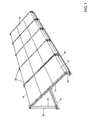
- the elevation system for solar modules of Fig. 1 shows a plurality of solar modules 10 held by a plurality of elevation devices 20.
- An uprising device 20 has a connection support 21 which is held by two support beams 22 and 23 which are respectively fastened to base supports such as T-beams 30.
- the solar modules 10 are the supporting elements between the elevation devices 20 and form the cross braces between the elevation devices 20.
- the Auf Plecksvortechniken 20 in the plane of the solar modules are not connected via another frame. The mechanical strength is achieved below by the connection with the two T-beams 30 and above by the solar modules themselves.
- connection carrier and the support beams may be formed, for example, of aluminum or any other light, non-corrosive metal or steel, while the connecting elements 24, 25 are preferably formed from plastic and are inserted into the connection carrier 21 and the two support beams 22 and 23.
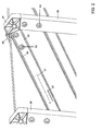
- a terminal strip 40 is mounted on the top of the connection carrier, which forms with their side surfaces 41 and 42 in conjunction with the projection 26 a receptacle for the solar module.
- the distance between the projection 26 and the side surface 41 is formed such that a solar module having a predetermined thickness is clamped in the receptacle when the terminal block is fastened to the surface of the connection carrier with fastening devices, not shown, such as screws.
- the attachment of the terminal block to the connection carrier can be done for example in a central web 43, which is adjacent to two stiffening ribs 44.
- the stiffening ribs 44 are used for mechanical stiffening of the terminal block and cause a permanent pressure of the side surfaces 41 and 42 on the side edge of the solar module 10.
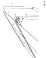
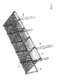
- the two support beams 22, 23 can each be screwed onto the base support 30, as shown in the FIGS. 1 . 3 and 4 can be seen schematically.
- connection carrier is so connected via the connecting elements 24, 25 with the support beams 22 and 23, that forms a small distance between the terminal block and projection 26, so that, for example, thin-film modules can be well secured.
- connection carrier in Fig. 2 is shown rotated about its longitudinal axis A by 180 ° and in turn via the connecting elements 24 and 25 with the support beams 22, 23rd connected, so is the in Fig. 2 represented protrusion 26 on the other side hidden by the connecting support, wherein the projection, which was on the other hidden side by the rotation of 180 ° on the in Fig.
- Fig. 5 is the connecting element 24 shown before it was inserted into the support bracket 22 or connecting bracket 21.
- the connecting element has a head piece 51 and two coupling elements 52 and 53.
- the coupling elements are inserted into the hollow beams 21 and 22, the coupling element 52 becomes, as in Fig. 2 can be seen, introduced into the connection carrier 21, while the coupling element 53 is inserted into the support bracket 22.
- the fasteners are not solid. Rather, the head piece and the coupling elements have reinforcing ribs 54.
- the coupling elements 52 and 53 further comprise bores 55, which in the inserted state are aligned with bores in the supports 21 and 22, so that a connecting pin such as a screw 80 can be made, as in FIG Fig. 2 can be seen.
- connection carrier 21 is connected to the lower support bracket 23 via a connecting element 25, which in the non-inserted state in Fig. 6 is shown in more detail.
- the connecting element 25, similar to the connecting element 24, has a head piece 71 and two coupling elements 72, 73.
- the coupling element 72 is completely inserted into the connection carrier 21.
- the support beam 23 is formed only by two side walls 23a and 23b between which the coupling element 73 is inserted, so that at the front, as in Fig. 3 it can be seen that the coupling element 73 is visible.
- the coupling elements 72 and 73 are connected in a similar manner as the coupling elements 52 and 53 with the carriers. This means that they have holes 75, with which the connecting element 25 is connected via connecting pins 80 with the carrier 21 and 23 respectively.
- a further bore 76 in the coupling element 73 serves for fastening the support carrier 23 and the connecting element 25 to the carrier 30, as in FIG Fig. 3 can be seen.
- connection of the support beam 22 to the carrier 30 in Fig. 1 Insulate by connecting elements, not shown.
- This connecting element is then similar to the connecting element 25 at the lower end connected to the carrier 30 while the upper end is connected to the support bracket 22.
- the two coupling elements would run opposite to each other from the head piece.
- Fig. 8 shows a further possibility of how a side edge of a solar module 10 can be held by a connection carrier 21.
- the side edge of the solar module 10 comprises a framing 11 which may extend over part of the side edge or over the entire side edge.
- the frame 11, which is part of the solar module 10 is clamped by a clamp 80 on a projection 26 provided on the connection support 21. This can be done for example by means of a bolt or a screw 81. Other clamping elements can also be used to create a frictional engagement between the frame 11 and projection 26.
- a simple assembly and disassembly of the solar modules is possible. Since the solar modules can rest over the entire length of their side edge on the projection and thus no punctiform loading, the further twisting or twisting of the solar module can be avoided.
- connection carrier e.g. a positive connection between the connection carrier and the solar module.
- the inventive Aufurticianssystem consisting of several Auf Parttechnischesvoriquesen has the advantage that the cost of materials is significantly reduced by the supporting solar modules, the construction times for a finished solar system can be reduced and solar modules of different sizes can be easily installed.
- the solar module is also insulated from the ground.
Landscapes
- Engineering & Computer Science (AREA)
- Physics & Mathematics (AREA)
- Life Sciences & Earth Sciences (AREA)
- Sustainable Development (AREA)
- Sustainable Energy (AREA)
- Thermal Sciences (AREA)
- Chemical & Material Sciences (AREA)
- Combustion & Propulsion (AREA)
- Mechanical Engineering (AREA)
- General Engineering & Computer Science (AREA)
- Roof Covering Using Slabs Or Stiff Sheets (AREA)
- Photovoltaic Devices (AREA)
Applications Claiming Priority (4)
| Application Number | Priority Date | Filing Date | Title |
|---|---|---|---|
| DE202008004756 | 2008-04-07 | ||
| DE202008005647 | 2008-04-23 | ||
| DE102008027451A DE102008027451A1 (de) | 2008-04-23 | 2008-06-09 | Aufständerungsvorrichtung und Aufständerungssystem |
| DE102008027452.6A DE102008027452B4 (de) | 2008-04-07 | 2008-06-09 | Aufständerungsvorrichtung für ein Solarmodul |
Publications (1)
| Publication Number | Publication Date |
|---|---|
| EP2108899A2 true EP2108899A2 (fr) | 2009-10-14 |
Family
ID=40795076
Family Applications (1)
| Application Number | Title | Priority Date | Filing Date |
|---|---|---|---|
| EP09005098A Withdrawn EP2108899A2 (fr) | 2008-04-07 | 2009-04-07 | Système de montage |
Country Status (1)
| Country | Link |
|---|---|
| EP (1) | EP2108899A2 (fr) |
Cited By (3)
| Publication number | Priority date | Publication date | Assignee | Title |
|---|---|---|---|---|
| NL2006883C2 (nl) * | 2011-06-01 | 2012-12-04 | Valk Systemen Bvvd | Kas met reeksen zonnepanelen. |
| EP2554925A3 (fr) * | 2011-07-26 | 2013-07-31 | M. Münch Elektrotechnik GmbH & Co. KG | Élément d'appui pour un module solaire |
| EP2789932A1 (fr) | 2013-04-10 | 2014-10-15 | Thales | Support d'objets sur container comprenant des coins ISO |
-
2009
- 2009-04-07 EP EP09005098A patent/EP2108899A2/fr not_active Withdrawn
Cited By (4)
| Publication number | Priority date | Publication date | Assignee | Title |
|---|---|---|---|---|
| NL2006883C2 (nl) * | 2011-06-01 | 2012-12-04 | Valk Systemen Bvvd | Kas met reeksen zonnepanelen. |
| EP2554925A3 (fr) * | 2011-07-26 | 2013-07-31 | M. Münch Elektrotechnik GmbH & Co. KG | Élément d'appui pour un module solaire |
| EP2789932A1 (fr) | 2013-04-10 | 2014-10-15 | Thales | Support d'objets sur container comprenant des coins ISO |
| FR3004524A1 (fr) * | 2013-04-10 | 2014-10-17 | Thales Sa | Support d'objets sur container comprenant des coins iso |
Similar Documents
| Publication | Publication Date | Title |
|---|---|---|
| EP2487435B1 (fr) | Liaison de serrage pour la fixation de composants en forme de plaques, notamment de modules solaires | |
| EP2187447A2 (fr) | Dispositif de montage pour modules solaires doté d'un grand ratio de face | |
| DE202012012485U1 (de) | Halter für ein Solarmodul | |
| DE102010005570A1 (de) | Profilelement zur Befestigung von Solarzellen und Solarzellenmodul | |
| EP0200050A1 (fr) | Module solaire avec équerre d'angle | |
| DE202009015122U1 (de) | Vorrichtung zum Abstützen von Solarmodulen | |
| EP3205953A1 (fr) | Système de montage d'éléments tabulaires et système solaire comprenant un tel système de montage | |
| DE202010000940U1 (de) | Profilelement zur Befestigung von Solarzellen und Solarzellenmodul | |
| EP2423622B1 (fr) | Dispositif de fixation avec éléments de montage et rail de support | |
| DE202010012937U1 (de) | Befestigungssystem | |
| DE112005002488T5 (de) | Verfahren und Vorrichtung zur Vermeidung der Verwindung eines gerahmten Solarmoduls | |
| WO2014075746A1 (fr) | Système de montage pour modules solaires | |
| EP3467228A1 (fr) | Fenêtre de toit pour le montage dans une ouverture de toit, dispositif formant toit et procédé de montage d'une fenêtre de toit | |
| DE102008027452B4 (de) | Aufständerungsvorrichtung für ein Solarmodul | |
| WO2025051823A1 (fr) | Pince pour fixer un cadre de module photovoltaïque | |
| DE102008009703A1 (de) | Haltevorrichtung für plattenförmige Elemente | |
| CH707265A2 (de) | Vorrichtung zur Verbindung eines Trägers für Strassenschilder mit einem Ständer und das entsprechende Strassenschild. | |
| EP0609651A1 (fr) | Elément de façade | |
| DE202010008421U1 (de) | Tragsystem für Solarmodule | |
| DE102010037831A1 (de) | Befestigungsvorrichtung an einem Gebäude | |
| WO2016156382A1 (fr) | Système de montage et procédé de montage | |
| DE202010017971U1 (de) | Vorrichtung zum Abstützen von Solarmodulen | |
| DE102015013262B3 (de) | Montagesystem für plattenförmige Körper, insbesondere Solarmodule | |
| DE102011086228A1 (de) | Solarmodulanordnung, Befestigungssystem und Trägerschiene | |
| DE202009013691U1 (de) | Klemme zur Anordnung eines Solarpanels auf einem Dach |
Legal Events
| Date | Code | Title | Description |
|---|---|---|---|
| PUAI | Public reference made under article 153(3) epc to a published international application that has entered the european phase |
Free format text: ORIGINAL CODE: 0009012 |
|
| AK | Designated contracting states |
Kind code of ref document: A2 Designated state(s): AT BE BG CH CY CZ DE DK EE ES FI FR GB GR HR HU IE IS IT LI LT LU LV MC MK MT NL NO PL PT RO SE SI SK TR |
|
| RAP1 | Party data changed (applicant data changed or rights of an application transferred) |
Owner name: VISPIRON AG |
|
| RAP1 | Party data changed (applicant data changed or rights of an application transferred) |
Owner name: VISPIRON ENGINEERING GMBH |
|
| STAA | Information on the status of an ep patent application or granted ep patent |
Free format text: STATUS: THE APPLICATION IS DEEMED TO BE WITHDRAWN |
|
| 18D | Application deemed to be withdrawn |
Effective date: 20131101 |