EP2108928A2 - Dispositif et procédé de surveillance de la capacité de fonctionnement d'un dispositif de traitement de récipients - Google Patents
Dispositif et procédé de surveillance de la capacité de fonctionnement d'un dispositif de traitement de récipients Download PDFInfo
- Publication number
- EP2108928A2 EP2108928A2 EP09153288A EP09153288A EP2108928A2 EP 2108928 A2 EP2108928 A2 EP 2108928A2 EP 09153288 A EP09153288 A EP 09153288A EP 09153288 A EP09153288 A EP 09153288A EP 2108928 A2 EP2108928 A2 EP 2108928A2
- Authority
- EP
- European Patent Office
- Prior art keywords
- vibration
- container treatment
- measurement signal
- vibration measurement
- evaluation
- Prior art date
- Legal status (The legal status is an assumption and is not a legal conclusion. Google has not performed a legal analysis and makes no representation as to the accuracy of the status listed.)
- Granted
Links
Images



Classifications
-
- G—PHYSICS
- G01—MEASURING; TESTING
- G01H—MEASUREMENT OF MECHANICAL VIBRATIONS OR ULTRASONIC, SONIC OR INFRASONIC WAVES
- G01H1/00—Measuring characteristics of vibrations in solids by using direct conduction to the detector
- G01H1/003—Measuring characteristics of vibrations in solids by using direct conduction to the detector of rotating machines
-
- B—PERFORMING OPERATIONS; TRANSPORTING
- B29—WORKING OF PLASTICS; WORKING OF SUBSTANCES IN A PLASTIC STATE IN GENERAL
- B29C—SHAPING OR JOINING OF PLASTICS; SHAPING OF MATERIAL IN A PLASTIC STATE, NOT OTHERWISE PROVIDED FOR; AFTER-TREATMENT OF THE SHAPED PRODUCTS, e.g. REPAIRING
- B29C49/00—Blow-moulding, i.e. blowing a preform or parison to a desired shape within a mould; Apparatus therefor
- B29C49/42—Component parts, details or accessories; Auxiliary operations
- B29C49/56—Opening, closing or clamping means
-
- B—PERFORMING OPERATIONS; TRANSPORTING
- B29—WORKING OF PLASTICS; WORKING OF SUBSTANCES IN A PLASTIC STATE IN GENERAL
- B29C—SHAPING OR JOINING OF PLASTICS; SHAPING OF MATERIAL IN A PLASTIC STATE, NOT OTHERWISE PROVIDED FOR; AFTER-TREATMENT OF THE SHAPED PRODUCTS, e.g. REPAIRING
- B29C49/00—Blow-moulding, i.e. blowing a preform or parison to a desired shape within a mould; Apparatus therefor
- B29C49/42—Component parts, details or accessories; Auxiliary operations
- B29C49/78—Measuring, controlling or regulating
-
- B—PERFORMING OPERATIONS; TRANSPORTING
- B67—OPENING, CLOSING OR CLEANING BOTTLES, JARS OR SIMILAR CONTAINERS; LIQUID HANDLING
- B67B—APPLYING CLOSURE MEMBERS TO BOTTLES JARS, OR SIMILAR CONTAINERS; OPENING CLOSED CONTAINERS
- B67B3/00—Closing bottles, jars or similar containers by applying caps
- B67B3/26—Applications of control, warning, or safety devices in capping machinery
-
- B—PERFORMING OPERATIONS; TRANSPORTING
- B67—OPENING, CLOSING OR CLEANING BOTTLES, JARS OR SIMILAR CONTAINERS; LIQUID HANDLING
- B67C—CLEANING, FILLING WITH LIQUIDS OR SEMILIQUIDS, OR EMPTYING, OF BOTTLES, JARS, CANS, CASKS, BARRELS, OR SIMILAR CONTAINERS, NOT OTHERWISE PROVIDED FOR; FUNNELS
- B67C3/00—Bottling liquids or semiliquids; Filling jars or cans with liquids or semiliquids using bottling or like apparatus; Filling casks or barrels with liquids or semiliquids
- B67C3/007—Applications of control, warning or safety devices in filling machinery
-
- B—PERFORMING OPERATIONS; TRANSPORTING
- B29—WORKING OF PLASTICS; WORKING OF SUBSTANCES IN A PLASTIC STATE IN GENERAL
- B29C—SHAPING OR JOINING OF PLASTICS; SHAPING OF MATERIAL IN A PLASTIC STATE, NOT OTHERWISE PROVIDED FOR; AFTER-TREATMENT OF THE SHAPED PRODUCTS, e.g. REPAIRING
- B29C49/00—Blow-moulding, i.e. blowing a preform or parison to a desired shape within a mould; Apparatus therefor
- B29C49/42—Component parts, details or accessories; Auxiliary operations
- B29C49/48—Moulds
- B29C2049/4879—Moulds characterised by mould configurations
- B29C2049/4892—Mould halves consisting of an independent main and bottom part
-
- B—PERFORMING OPERATIONS; TRANSPORTING
- B29—WORKING OF PLASTICS; WORKING OF SUBSTANCES IN A PLASTIC STATE IN GENERAL
- B29C—SHAPING OR JOINING OF PLASTICS; SHAPING OF MATERIAL IN A PLASTIC STATE, NOT OTHERWISE PROVIDED FOR; AFTER-TREATMENT OF THE SHAPED PRODUCTS, e.g. REPAIRING
- B29C49/00—Blow-moulding, i.e. blowing a preform or parison to a desired shape within a mould; Apparatus therefor
- B29C49/42—Component parts, details or accessories; Auxiliary operations
- B29C49/56—Opening, closing or clamping means
- B29C2049/566—Locking means
- B29C2049/5661—Mechanical
-
- B—PERFORMING OPERATIONS; TRANSPORTING
- B29—WORKING OF PLASTICS; WORKING OF SUBSTANCES IN A PLASTIC STATE IN GENERAL
- B29C—SHAPING OR JOINING OF PLASTICS; SHAPING OF MATERIAL IN A PLASTIC STATE, NOT OTHERWISE PROVIDED FOR; AFTER-TREATMENT OF THE SHAPED PRODUCTS, e.g. REPAIRING
- B29C2949/00—Indexing scheme relating to blow-moulding
- B29C2949/07—Preforms or parisons characterised by their configuration
- B29C2949/0715—Preforms or parisons characterised by their configuration the preform having one end closed
-
- B—PERFORMING OPERATIONS; TRANSPORTING
- B29—WORKING OF PLASTICS; WORKING OF SUBSTANCES IN A PLASTIC STATE IN GENERAL
- B29C—SHAPING OR JOINING OF PLASTICS; SHAPING OF MATERIAL IN A PLASTIC STATE, NOT OTHERWISE PROVIDED FOR; AFTER-TREATMENT OF THE SHAPED PRODUCTS, e.g. REPAIRING
- B29C33/00—Moulds or cores; Details thereof or accessories therefor
- B29C33/20—Opening, closing or clamping
- B29C33/26—Opening, closing or clamping by pivotal movement
-
- B—PERFORMING OPERATIONS; TRANSPORTING
- B29—WORKING OF PLASTICS; WORKING OF SUBSTANCES IN A PLASTIC STATE IN GENERAL
- B29C—SHAPING OR JOINING OF PLASTICS; SHAPING OF MATERIAL IN A PLASTIC STATE, NOT OTHERWISE PROVIDED FOR; AFTER-TREATMENT OF THE SHAPED PRODUCTS, e.g. REPAIRING
- B29C49/00—Blow-moulding, i.e. blowing a preform or parison to a desired shape within a mould; Apparatus therefor
- B29C49/02—Combined blow-moulding and manufacture of the preform or the parison
- B29C49/06—Injection blow-moulding
-
- B—PERFORMING OPERATIONS; TRANSPORTING
- B29—WORKING OF PLASTICS; WORKING OF SUBSTANCES IN A PLASTIC STATE IN GENERAL
- B29C—SHAPING OR JOINING OF PLASTICS; SHAPING OF MATERIAL IN A PLASTIC STATE, NOT OTHERWISE PROVIDED FOR; AFTER-TREATMENT OF THE SHAPED PRODUCTS, e.g. REPAIRING
- B29C49/00—Blow-moulding, i.e. blowing a preform or parison to a desired shape within a mould; Apparatus therefor
- B29C49/28—Blow-moulding apparatus
- B29C49/30—Blow-moulding apparatus having movable moulds or mould parts
- B29C49/36—Blow-moulding apparatus having movable moulds or mould parts rotatable about one axis
-
- B—PERFORMING OPERATIONS; TRANSPORTING
- B29—WORKING OF PLASTICS; WORKING OF SUBSTANCES IN A PLASTIC STATE IN GENERAL
- B29C—SHAPING OR JOINING OF PLASTICS; SHAPING OF MATERIAL IN A PLASTIC STATE, NOT OTHERWISE PROVIDED FOR; AFTER-TREATMENT OF THE SHAPED PRODUCTS, e.g. REPAIRING
- B29C49/00—Blow-moulding, i.e. blowing a preform or parison to a desired shape within a mould; Apparatus therefor
- B29C49/42—Component parts, details or accessories; Auxiliary operations
- B29C49/56—Opening, closing or clamping means
- B29C49/5601—Mechanically operated, i.e. closing or opening of the mould parts is done by mechanic means
- B29C49/5602—Mechanically operated, i.e. closing or opening of the mould parts is done by mechanic means using cams
-
- B—PERFORMING OPERATIONS; TRANSPORTING
- B29—WORKING OF PLASTICS; WORKING OF SUBSTANCES IN A PLASTIC STATE IN GENERAL
- B29C—SHAPING OR JOINING OF PLASTICS; SHAPING OF MATERIAL IN A PLASTIC STATE, NOT OTHERWISE PROVIDED FOR; AFTER-TREATMENT OF THE SHAPED PRODUCTS, e.g. REPAIRING
- B29C49/00—Blow-moulding, i.e. blowing a preform or parison to a desired shape within a mould; Apparatus therefor
- B29C49/42—Component parts, details or accessories; Auxiliary operations
- B29C49/56—Opening, closing or clamping means
- B29C49/5612—Opening, closing or clamping means characterised by bottom part movement
Definitions
- the invention relates to a device for executing a cam-controlled mechanical movement, hereafter referred to as a movement execution device, and more particularly to a container treatment device having a movement execution device according to the preamble of claim 1 and a method for monitoring the operability of a container treatment device having a movement execution device according to the preamble of claim 13.
- Container treatment apparatus is hereinafter referred to as a collective term for apparatuses for producing containers, in particular for blow molding containers, apparatuses for labeling containers, apparatuses for filling containers, devices for closing containers and other devices which perform processing steps in the manufacture or filling of containers , as well as combinations of these used.
- thermoplastic preforms for example made of polyethylene terephthalate (PET) in one of Blasformungsvorraum upstream heating station heated so that they can then be deformed in the blow molding device in a blow mold by blow molding or by stretch blow molding, so as to reform the preform into a desired container shape.
- the preforms are conveyed, for example, on a link chain with receiving mandrels.
- the heated preforms are then transferred by means of a transfer device with a transfer star in the actual blow mold in the blow molding.
- a blow mold consists of two half-foldable mold halves and a mold bottom, in each of which recesses corresponding to the shape of a corresponding part of the outer surface of the container to be produced, are formed.
- the tuyere After a preform has been supplied to the unfolded tuyere, the tuyere is closed and transported on an outer circumference of a continuously rotating impeller in the tuyere, the container in the tuyere being blown or stretch blown.
- a variety of blow molds is arranged distributed.
- the blow mold opens and the molded container is fed via an output device with an output star of a container output and then further into e.g. a container collection device or on a container conveyor belt for further transport to downstream container treatment devices, such. a filling and / or a labeling device.
- mechanical curves are used for unlocking the blow mold, opening the blow mold, closing and locking the blow mold, and mechanical curves for lowering and raising the blow mold bottoms and a mechanical curve for stretching the preforms using a stretch rod.
- All of these mechanical curves or motion-implementing devices perform a cam-controlled mechanical movement of partially heavy device parts.
- the performance of container processing devices is constantly increasing. Therefore, the load on these machines and especially the mechanical load on the molds and the mechanical curves is increasing. Therefore, it is extremely important that these machines, and in particular the motion-executing devices (mechanical curves), be regularly and meticulously maintained and precisely adjusted.
- a container treatment device is therefore designed so that lower quality parts supplied can not result in the destruction of device components, particularly the motion delivery devices.
- Thetecsaus operationsvoriques can for example be sprung mounted and swing back in case of overload. Nevertheless, an accumulation of extreme loads, such as occur in the supply of parts of lower quality, lead to an adjustment of the mechanical components, in particular components of the mechanical curve. It is all the more important that the container treatment device with the motion delivery devices be regularly checked and maintained.
- Another problem is the pressure on machine operators to maximize the manufacturing capacity of containers. This often results in maintenance intervals not being met. As a result, small adjustments of the mechanical components, including the mechanical curves, may increase or even further diminish small damages, thus permanently destroying the machine.
- the present invention is therefore based on the object to recognize special charges ofabsolusaus entrysvoroplastyen or the mechanical curves in an early stage and to detect adjustments or damage also at an early stage. Another object is, depending on the size of an adjustment or the severity of damage, to generate an indication of required maintenance work or even automatically bring about a shutdown of the container treatment device in order to protect the container treatment device, or in particular thethermsaus enclosuresvoruzeen from destruction or to force the machine operator to shut down and carry out required maintenance work.
- a container treatment apparatus for treating containers comprises at least one or a plurality of movement execution devices, ie devices for Performing a cam-controlled, mechanical movement (mechanical curve).
- the container treatment apparatus comprises at least one vibration sensor arranged in vibration communication with the motion execution apparatus for converting a mechanical vibration of at least a portion of the motion execution apparatus into a vibration measurement signal and outputting the vibration measurement signal, and further an evaluation means configured to evaluate at least one vibration measurement signal generated by the vibration sensor is.
- An advantage of the container treatment device according to the invention is that at least one vibration sensor is attached to a sensitive mechanical component, such as the movement execution device, and that by measuring vibrations of parts or portions of the movement execution device sensitive and early small adjustments of the mechanical curve or even adjusted rotating components can be detected by changes in the vibration behavior of the affected parts of the movement execution.
- the device according to the invention thus utilizes the effects known per se, that an adjusted mechanical curve or displaced rotating components in the device can cause guided parts or rotating parts to enter the mechanical curve less smoothly, to be able to grind along the leading curve or else can lead to shocks with the leading curve. It is also known that imbalances in fast-rotating waves lead to vibrations. The effects of these effects on the mechanical vibration of at least a portion of theassesaus enclosuresvorraum is sensitive and reliable measured by the present invention arranged vibration sensors. Depending on the nature of the expected load or disturbance or damage, a suitable evaluation method for the vibration measurement signal is selected so that deviations from the vibration behavior of a well-maintained, operational motion execution device can be detected early, reliably and clearly.
- the evaluation means is designed to detect, based on a result of the evaluation of the vibration measurement signal, whether there is a need for maintenance or whether a mechanical adjustment, damage and / or excessive load has occurred on a mechanical component of the movement execution device.
- the automatic detection by the evaluation means provides a more reliable protection of the movement execution device and, overall, the container treatment device than the monitoring of maintenance intervals by the operators. In particular, a need for maintenance or an adjustment or damage, too high a load can be recognized early within a maintenance interval.
- the motion execution device may be selected from a group of devices including a device for guiding a blow mold during blow molding of a container, a device for opening and / or closing a blow mold, for example for moving a blow mold half towards another blow mold half and / or in the opposite direction, a device for locking the blow mold halves, a device for unlocking the blow mold halves, a device for raising and lowering a Blasform réelle, a device for stretching a preform, z. B. for guiding a stretch rod, combinations thereof or the like.
- the present invention can be applied to all sorts of sensitive parts of a blow molding apparatus which rely on precise mechanical guidance.
- the motion execution device may include a leading component and / or a guided component.
- the leading component comprises in particular the molded part with the mechanically formed curve shape.
- the guided component comprises the part which is guided by the mechanically formed curve exactly along the shape of the curve.
- the blow mold can be guided along a substantially circular guide curve during transport, with the blow mold representing the guided component and the guide curve representing the leading component.
- the at least one vibration sensor is arranged in vibration communication with the leading component.
- the leading component is stored, for example, quiet or stationary, so that disturbances in operation by adjustment or damage to the mechanical curve more clearly in the vibration behavior or in the vibration measurement signal of the leading component from the normal state stand out than that for the guided components of the case.
- the leading component may comprise a main frame of the container treatment device.
- the main body of the container treatment apparatus can detect vibration changes by adjusting or damaging any movement executing apparatus for a vibration sensor mounted to the main body in vibration communication, particularly when suitably coupled to the motion execution devices, so that a vibration sensor can be used to monitor a plurality of motion execution devices.
- the at least one vibration sensor may also be arranged in vibration communication with a guided component.
- a guided component Depending on the type of mechanical curve and design of the guided component, such an attachment of the vibration sensor can also detect changes in the vibration behavior of the movement execution device more directly or more sensitively than when it is attached to the guiding element.
- the evaluation means may be adapted to detect when, based on the evaluation of the vibration measurement signal, a need for intervention by an operator in the ongoing operation of the container treatment device is detected.
- the automatic detection of a need to intervene as a result of continuous monitoring of the vibration performance of the motion execution device allows a more reliable monitoring of the operation of the container treatment device than the monitoring of the container treatment device by operators.
- the evaluation means is adapted to generate a signal which causes the decommissioning of the container treatment device. So, in the example an early detected small damage, the container treatment device are effectively protected from major damage.
- the evaluation means may be configured to compare a signal representative of an amplitude of a vibration of at least one part of the motion execution device with one or more adjustable limit values for the signal.
- the signal representative of the oscillation may be the time domain measured vibration measurement signal or the time dependence of the oscillation amplitude, or a signal derived by averaging in time, low pass filtering or bandpass filtering.
- the threshold may be a time-domain amplitude limit, or an average threshold, a low-pass filtered, or a band-pass filtered threshold.
- the evaluation means may also be designed to break the oscillation measurement signal into frequency bands and to evaluate frequency components of the thus decomposed oscillation measurement signal in suitably selected frequency bands.
- a mechanical resonance or its changes can be used as an indicator for adjustments or damage.
- specific frequency components outside of the frequency spectrum possibly dominating mechanical resonances can be used as an indicator for detecting adjustments or damage.
- the evaluation of a frequency component is preferably carried out in "critical" or indicative frequency bands, in which, for example, a mechanical resonance or a frequency component indicative of an adjustment or a damage of the motion execution device occurs.
- the evaluation of a frequency component may occur just outside such a critical frequency band.
- frequency bands could be used for evaluation in which frequency components have been caused due to increased friction, grinding or scratching or even impact between guided and leading components of the motion delivery device.
- the evaluation means can also be designed to provide additional information about a supposed cause, for example an adjustment, a shock, a damage or a lubricant requirement, or else an indication of a specific displaced or damaged mechanical component, for example the number of an affected component from a Variety of essentially identical components, such as the number of an affected blow mold from a variety of blow molds to produce.
- a supposed cause for example an adjustment, a shock, a damage or a lubricant requirement
- an indication of a specific displaced or damaged mechanical component for example the number of an affected component from a Variety of essentially identical components, such as the number of an affected blow mold from a variety of blow molds to produce.
- the container treatment device may also be provided a display means.
- the display means may be used for outputting derived numerical values relating to the vibration measurement signal or a graphical representation of the vibration measurement signal or for displaying results of the evaluation of the vibration measurement signal.
- the display means may be, for example, a computer monitor.
- the evaluation means can be arranged integrated directly in a vibration sensor. Such "intelligent" vibration sensor units can relieve a central evaluation unit or a central control unit of the container treatment device by removing the partial, e.g. compute intensive evaluation in the vibration sensor unit itself. The evaluation means then for example gives information to a higher level device control unit, e.g. on an excessive load of the relevanttecsaus enclosuresvorraum to respond.
- a central evaluation unit can be provided, to which the vibration measurement signals can be supplied or supplied by one or more vibration sensors.
- the central evaluation unit then comprises at least one evaluation means for evaluating the vibration signal of the at least one vibration sensor or a plurality of evaluation means assigned to a respective vibration sensor.
- the central evaluation unit may also be integrated in a higher-level central control unit for controlling the container treatment device.
- the complete integration of the evaluation in a central control unit can allow a more accurate evaluation, a more targeted adjustment of the output of the evaluation, or to take measures or interventions in the operation.
- a method for monitoring the operability of a container treatment apparatus having at least one motion execution device and at least one vibration sensor arranged in vibration communication with the motion execution device.
- the method comprises the following steps: a) detecting at least one vibration measurement signal output by at least one vibration sensor, and b) evaluating the at least one vibration measurement signal.
- the step b) of the method may include comparing the vibration measurement signal with standard signals and norm values and determining whether deviations outside of an adjustable tolerance range occur around the standard signal or the standard variables. By adjusting the tolerance range, the sensitivity or accuracy of detecting whether there is a need for operator intervention in ongoing operation of the container treatment apparatus can be adjusted.
- the method may further comprise a step c) of outputting, based on the evaluation of the vibration measurement signal, information indicating that there is a need for operator intervention in a running operation of the container treatment apparatus.
- Step c) may include generating a signal that causes the decommissioning of the machine.
- the step c) may also comprise comparing a signal representative of the amplitude of a vibration of at least a portion of the motion execution device or a quantity derived therefrom with one or more adjustable limit signals.
- the comparison may comprise a comparison of an amplitude signal with an amplitude limit value and / or the comparison of a time position with a time position limit value.
- Step c) may also include decomposing the vibration measurement signal into frequency components and evaluating frequency components in suitable selected frequency bands.
- the evaluation may then be performed in "critical" or indicative frequency bands, for example in a frequency band in which a mechanical resonance occurs, or in a frequency band in which a frequency component indicative of an adjustment or damage of the motion execution device occurs.
- the evaluation in the frequency domain may be just outside of frequency bands indicative of operation within the tolerance limits, e.g. outside of frequency bands in which mechanical resonances occur in the nominal mode, so as to detect vibration "noises” caused, for example, by increased friction, by grinding or scratching between mechanical components of the motion-implementing device.
- Step c) may also include generating additional information about a suspected cause or an indication of an obstructed or damaged mechanical component of the motion execution device.
- the information about a supposed cause may be, for example, information as to whether it is an adjustment or a damage or a lubrication need of the motion execution device.
- the indication of a particular displaced or damaged mechanical component may be, for example, a number of an affected component of a plurality of substantially identical components, such as the number of a blow mold of a plurality of blow molds.
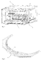
- Fig. 1 shows as an example of a container treatment device 1 is a view of a A blow molding apparatus 2 comprising: a main frame 4 having a plurality of main frame members 6, a feeder (not shown) having a feed star (not shown) for feeding preforms for the container to be formed in the blow molding apparatus from a blower pre-heater apparatus for heating Preforms (not shown), a blowing wheel for transporting a plurality of blow molds (not shown), a removal device 10 with an outlet star 12 for carrying out preforms from the blow molding device, for example in subsequently arranged container treatment devices, such as filling, sealing and / or labeling , a guide curve 14 (see. Fig. 2 ), a locking curve 18, an opening / closing curve (22, see FIG Fig. 4 ) and an unlocking device.
- a guide curve 14 see. Fig. 2
- a locking curve 18 an opening / closing curve (22, see FIG Fig. 4 ) and an unlocking device.
- preforms are introduced into the blow molding apparatus 2 by means of the feed star (not shown) and transferred to a blow mold designated by the blower wheel.
- the blow mold is fully opened at the moment of transfer and is transported along a circular path on the rotating blowing wheel. In this case, the blow mold moves past the feed star (not shown), picking up a preform brought up by the feed star (not shown).
- the blowing wheel blow molds which are distributed over the circumference of the blowing wheel 8, continuously guided on a circular path along various processing or process stations up to a discharge device.
- a blow mold bottom is guided from below to the blow mold halves to be locked together and locked by a corresponding locking device (not shown) with the two closed blow mold halves.
- a nozzle is sealingly introduced to an upper opening of the blow mold and to the preform already formed on the container opening, and then the preform is expanded by supplying compressed air into the interior of the preform until the outer wall of the preform abuts the inner surface of the blow mold.
- the blow mold with the container formed therein runs on the unlocking curve 26 (cf. Fig. 5 ), which causes the tuyeres to be unlocked.
- the unlocked blow mold runs at the opening portion of the opening / closing cam 22 (FIG. Fig. 4 ), which causes the blow mold to be opened.
- the molded container is removed from the opened blow mold by the subsequent discharge device 12 and discharged.
- the guide cam 14, the locking cam 18, the blow molding tray lifting device (not shown), the opening / closing cam 22, and the unlocking cam 26 are examples of moving execution devices.
- vibration sensors are mounted in vibration communication with the guided and guiding components of the mechanical curve interacting in operation, such as in the FIGS FIGS. 2 to 5 shown.
- the vibration sensors convert a mechanical vibration of at least a portion of the motion execution device into a vibration measurement signal that is for evaluation and based on a result of the evaluation for detecting mechanical vibration of the motion execution device.
- Fig. 2 shows the stretching curve 14, which serves for guiding the blow mold during the blow molding of the container, and which comprises in a central region a vibration sensor, the guide curve sensor 16.
- Fig. 3 shows the locking curve 18, which causes the locking of the blow mold halves.
- a vibration sensor In the vicinity of the region of the locking curve 18, at the first with an adjustment, high load or damage, for example, by high pressure or loosening of the locking curve 18 is to be expected, is also a vibration sensor, the locking curve sensor 20, attached.
- Fig. 4 shows the opening / closing curve 22, which causes the opening and closing of the blow mold halves and the one Movement on the circular path transported blow molds leading furrow, which in Fig. 4 is particularly well visible.
- the opening / closing curve 22 or the groove comprises a region which causes the opening of the blow molds and in which an opening curve sensor 24 'and a closing curve sensor 24 are arranged.
- FIG. 5 the unlocking device 26 with the about a vertically oriented axis of rotation pivotally arranged Entriegelungseingreifkurve 27, which engages only in the case of misalignment and is guided on their horizontal rotational movement of a Entriegelungskurve 28.
- a Entriegelungskurvensensor 31 is arranged at a with respect to the blowing wheel outer or opposite side of the Entriegelungskurve 28 .
- the unlocking curve 28 is a leading element 32, which stabilizes the pivotal movement of the Entriegelungseingreifkurve 27, and the Entriegelungseingreifkurve 27 is thus also a leading element 32.
- the pivotal movement of the Entriegelungskurve 28 by a with respect to Circular movement of the Blasrads 8 radially inwardly and outwardly movable and mounted in an ironing device 30 Activation push rod 29 is activated.
- a vibration sensor (not shown) is also attached to an outer side with respect to the position of the blowing wheel 8. This sensor is activated during the periods of transfer in and return Position of Entriegelungskurve 27 arranged in a guided element.
- the term "arranged in vibration communication" means that vibrations generated by the guidance of the guided member along a leading member in this motion execution apparatus are transmitted to a vibration measurement sensor.
- Fig. 6 illustrates various embodiments for the coupling between vibration sensors and evaluation means for a system having a plurality of, for example, three vibration sensors 36-1, 36-2, 36-3 and respectively associated evaluation means 40-1, 40-2, 40-3, and also a central evaluation unit 44, eg in the form of a programmable logic controller PLC and a downstream visualization unit 46.
- a central evaluation unit 44 eg in the form of a programmable logic controller PLC and a downstream visualization unit 46.
- an associated evaluation means 40-1, 40-2, 40-3 is integrated in the sensor in each of the vibration measurement sensors 36-1, 36-2, 36-3.
- the information signals 42-1, 42-2, 42-3 generated by the evaluation means 40-1, 40-2, 40-3 are supplied to a central evaluation unit 44.
- the information signals 42-1, 42-2, 42-3 supplied to the central evaluation unit 44 contain information as to whether a particular load, an adjustment or even damage has occurred at the movement execution device with which the corresponding vibration sensor is arranged in vibration communication. From these information arriving in the central evaluation unit 44, the central evaluation unit 44 generates information about how to react to the high load, adjustment or damage, and carries this information Visualization unit 46 too. For example, information about how to respond to excessive load, misalignment, or damage could be: a recommended machine stop, the recommended issuance of a warning signal, or an indication of which motion execution device is involved, and so on.
- the vibration measurement signals 38-1, 38-2, 38-3 generated by a plurality of, for example, three vibration measurement sensors 36-1, 36-2, 36-3 are fed directly to a central evaluation means 40. Evaluation of the vibration measurement signals 38-1, 38-2, 38-3 generated by the individual vibration measuring sensors takes place in the evaluation means 40. With the information from the evaluations of the individual vibration measurement signals, the central evaluation means 40 generates information on how to respond to an overestimated load, to an adjustment or to a vibration signal characteristic indicative of damage.
- the visualization unit 46 is relieved to the extent that the often computation-intensive evaluation of the vibration measurement signals takes place in the central evaluation unit 44 and the visualization unit 46 does not need to execute it.
- information signals 42 are generated and supplied via an information line to the visualization unit 46, the information obtained therefrom and from a central device control unit 44 Notes or the above information generated for the reaction.
- the central device control unit 44 can be, for example, a programmable logic controller (PLC), an industrial computer with a soft PLC and / or a visualization program, a company or device specific control solution, or a computer controlled by a suitable software program, e.g. a personal computer (PC).
- PLC programmable logic controller
- the display means 48 is on the visualization unit 46, e.g. a PC, connected monitor.
- the visualization unit 46 with the display means 48 can generally display both the information prepared by the higher-level device control unit 44 and the evaluation-based information 42 output by the evaluation means 40, 40-1, the vibration sensors 36-1, 36-2, 36.3 measured vibration measurement signals 38-1, 38-2, 38-3, for example, tabular or in graphical form represent.
- the evaluation or the evaluation not only reports the exceeding of certain limits, but provides additional information about their cause.
- the designation of an affected motion execution device or the number could be displayed by a motion execution device of a plurality of similar motion execution devices, such as the number of a blow mold, that caused the error. This avoids prolonged searching of the affected motion execution device by the operator.
- maximum values for example of vibration measurement signals, or also adjustable threshold values or historical trends, for example trends of directly detected or filtered vibration measurement signals or of weighted information, are displayed, which enable a high load, an adjustment or tracing damage to a motion execution device as accurately as possible.
- the vibration measurement signals measured by the vibration sensors are generally evaluated by comparing the amplitude of vibrations with one or more adjustable limits. Another variant is to sum several or all frequencies in order to calculate a total impact, for example.
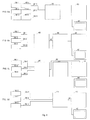
- the Fig. 7a to 7d show by way of example and schematically various embodiments, how a vibration measurement signal can be evaluated or evaluated.
- Fig. 7a shows the time dependence of the amplitude of a vibration measurement signal A (t), ie the course of the amplitude A (t) over time t, ie the vibration measurement signal as generated by a vibration sensor.
- a vibration sensor attached to a mechanical curve generates an approximately constant vibration measurement signal 50, except for noise.
- the vibration measurement signal 50 changes rapidly, as in FIG Fig. 7a is shown and rises rapidly, for example because a guided element has just come in contact with the mechanical curve.
- the amplitude A (t) When the maximum contact or pressure of the guided element with the mechanical curve has been reached, the amplitude A (t) also reaches a maximum value at an increased level.
- the duration 52, .DELTA.t of the change of the amplitude A (t) is determined and compared with a limit value.
- the tolerance or the tolerated play of the guide is set by the mechanical curve.
- Fig. 7b shows the time course of an amplitude A (t) of a vibration measurement signal 50 'measured on a motion execution device.
- This time course arises, for example, in that repeatedly guided elements run along the motion execution device in question.
- a "grinding noise” in the form of a high frequency noise having a noise amplitude 54 is measured by the affected vibration sensor.
- the tolerable clearance or “rattle” can be adjusted by a suitable choice of a threshold value for the amplitude 54, N of the noise of the "sweeping noise” of the guided element on the mechanical curve.
- FIG. 7c Figure 12 shows the time course of a vibration signal amplitude A (t) measured by a vibration sensor in vibration communication with a mechanical curve along which repeated guided elements are guided.
- a (t) measured by a vibration sensor in vibration communication with a mechanical curve along which repeated guided elements are guided.
- a "grinding noise” is produced at the contact of the guided element with the mechanical curve as the leading element at a certain value 56. If the curve is displaced over the course of the operating time, the amplitude of the "grinding noise” decreases during the contact of the guided one Elements with the leading element to a value 56 'too.
- Fig. 7c shows a threshold value 58 for the tolerable magnitude (amplitude) of the "grinding noise”. The affected mechanical curve is judged to be misaligned when the "grinding noise" 56 'rises above the threshold value 58 as in the right part of FIG Fig. 7c shown.
Landscapes
- Engineering & Computer Science (AREA)
- Mechanical Engineering (AREA)
- Manufacturing & Machinery (AREA)
- Physics & Mathematics (AREA)
- General Physics & Mathematics (AREA)
- Blow-Moulding Or Thermoforming Of Plastics Or The Like (AREA)
- Measurement Of Mechanical Vibrations Or Ultrasonic Waves (AREA)
- Beans For Foods Or Fodder (AREA)
Applications Claiming Priority (1)
| Application Number | Priority Date | Filing Date | Title |
|---|---|---|---|
| DE102008010885A DE102008010885A1 (de) | 2008-02-25 | 2008-02-25 | Vorrichtung und Verfahren zum Überwachen der Betriebsfähigkeit einer Behälterbehandlungsvorrichtung |
Publications (3)
| Publication Number | Publication Date |
|---|---|
| EP2108928A2 true EP2108928A2 (fr) | 2009-10-14 |
| EP2108928A3 EP2108928A3 (fr) | 2015-12-16 |
| EP2108928B1 EP2108928B1 (fr) | 2021-05-05 |
Family
ID=40896708
Family Applications (1)
| Application Number | Title | Priority Date | Filing Date |
|---|---|---|---|
| EP09153288.7A Active EP2108928B1 (fr) | 2008-02-25 | 2009-02-20 | Dispositif et procédé de surveillance de la capacité de fonctionnement d'un dispositif de traitement de récipients |
Country Status (3)
| Country | Link |
|---|---|
| EP (1) | EP2108928B1 (fr) |
| CN (2) | CN101518948A (fr) |
| DE (1) | DE102008010885A1 (fr) |
Cited By (7)
| Publication number | Priority date | Publication date | Assignee | Title |
|---|---|---|---|---|
| EP2397305A3 (fr) * | 2010-06-18 | 2014-11-05 | Krones AG | Machine de formage par soufflage avec tige d'étirage |
| WO2018215245A1 (fr) * | 2017-05-22 | 2018-11-29 | Khs Gmbh | Procédé de surveillance d'un processus |
| WO2019042621A1 (fr) * | 2017-09-04 | 2019-03-07 | Krones Ag | Installation de traitement de récipient et procédé de détection de propriétés de roulement d'un rouleau sur une came de levage d'une telle installation de traitement de récipient |
| EP2368691B1 (fr) | 2010-03-26 | 2019-08-21 | Krones AG | Procédé de fabrication de récipients en matière synthétique et dispositif pour réaliser le procédé |
| EP2108928B1 (fr) | 2008-02-25 | 2021-05-05 | Krones AG | Dispositif et procédé de surveillance de la capacité de fonctionnement d'un dispositif de traitement de récipients |
| CN114538351A (zh) * | 2020-11-25 | 2022-05-27 | 克朗斯公司 | 容器处理设备中的凸轮元件的位置监测 |
| CN114599500A (zh) * | 2019-10-24 | 2022-06-07 | 西得乐集团 | 控制用于制造塑料容器的制造机械的活动构件移动的移动控制装置 |
Families Citing this family (11)
| Publication number | Priority date | Publication date | Assignee | Title |
|---|---|---|---|---|
| DE102009040977B4 (de) * | 2009-09-11 | 2022-12-15 | Krones Aktiengesellschaft | Behältnisbehandlungsanlage und ein Behältnisbehandlungsverfahren zum Behandeln von mit einem Produkt befüllbaren Behältnissen |
| US8573963B2 (en) * | 2011-04-01 | 2013-11-05 | Graham Engineering Corporation | Adjustable multiple-piece cam track |
| DE102011050715A1 (de) * | 2011-05-30 | 2012-12-06 | Krones Aktiengesellschaft | Verfahren und werkzeug zur informationsausgabe |
| DE102012104754A1 (de) * | 2012-06-01 | 2013-12-05 | Krones Ag | Blasformmaschine mit umlaufender Verriegelungskurve |
| DE102012023703A1 (de) | 2012-12-05 | 2014-06-05 | Krones Ag | Blasformmaschine |
| AT14535U1 (de) * | 2014-09-19 | 2016-01-15 | Engel Austria Gmbh | Vorrichtung zur Detektion des Aufeinandertreffens von Maschinenteilen |
| DE102015205039A1 (de) | 2015-03-19 | 2016-09-22 | Krones Ag | Verfahren zur Kollisionsüberwachung |
| DE102017120477A1 (de) * | 2017-09-06 | 2019-03-07 | Krones Ag | Vorrichtung zum Umformen von Kunststoffvorformlingen zu Kunststoffbehältnissen mit Sensorelement zur Belastungsmessung |
| CN107471280B (zh) * | 2017-09-30 | 2020-01-31 | 重庆市臻憬科技开发有限公司 | 一种具有过载保护且刀具无粘附的切菜机 |
| EP4249863B1 (fr) * | 2022-03-24 | 2026-02-11 | Sidel Participations | Système de surveillance d'anomalies de vibration dans des machines de conditionnement |
| DE102023103363A1 (de) * | 2023-02-13 | 2024-08-14 | Khs Gmbh | Verfahren zum Überwachen einer Behälterbehandlungsanlage |
Family Cites Families (38)
| Publication number | Priority date | Publication date | Assignee | Title |
|---|---|---|---|---|
| US758964A (en) | 1903-08-22 | 1904-05-03 | Hadley E Green | Railroad-crossing. |
| US3553809A (en) | 1967-01-25 | 1971-01-12 | Tokai Rika Co Ltd | Forging method for producing a hollow body |
| US3553636A (en) * | 1969-01-27 | 1971-01-05 | Bindicator Co | Noncontact ultrasonic interface viscosity and percent solid detecting device |
| JPS599842B2 (ja) | 1974-07-12 | 1984-03-05 | 日本精工株式会社 | 回転体の損傷検出装置 |
| US4520674A (en) | 1983-11-14 | 1985-06-04 | Technology For Energy Corporation | Vibration monitoring device |
| DE3408659A1 (de) | 1984-03-09 | 1985-09-19 | Vdo Adolf Schindling Ag, 6000 Frankfurt | Vorrichtung zu anzeige von fehlern |
| DE3515061A1 (de) | 1985-04-26 | 1986-10-30 | Fried. Krupp Gmbh, 4300 Essen | Verfahren und vorrichtung zur ueberwachung von maschinenteilen |
| DE3627796C1 (en) | 1986-08-16 | 1987-10-22 | Klaus Dipl-Ing Nordmann | Device for monitoring the state and breakage of rotating tools by means of measurements of structure-borne sound |
| CH672955A5 (fr) * | 1987-05-12 | 1990-01-15 | Elpatronic Ag | |
| DE3734487A1 (de) | 1987-10-12 | 1989-04-20 | Grs Ges Reaktorsicherheit | Verfahren zur ueberwachung der betriebssicheren arbeitsweise und schadensfrueherkennung komplizierter technischer anlagen |
| DE4023663C2 (de) | 1989-07-31 | 1996-02-01 | Siemens Ag | Verfahren zur Diagnose der mechanischen Eigenschaften einer Maschine, die rotierende Bauteile aufweist |
| US5109700A (en) | 1990-07-13 | 1992-05-05 | Life Systems, Inc. | Method and apparatus for analyzing rotating machines |
| DE4116345A1 (de) | 1991-05-18 | 1992-11-19 | Rhein Westfael Tech Ueberwach | Verfahren zur schadensfrueherkennung |
| ES2067100T3 (es) | 1991-08-08 | 1995-03-16 | Ossberger Turbinen | Dispositivo para fabricar una pieza preconformada para el moldeo por soplado de un fuelle. |
| JP3250842B2 (ja) | 1992-07-07 | 2002-01-28 | マツダ株式会社 | 絞付成形品における中空射出成形方法 |
| DE4320411C2 (de) * | 1993-06-22 | 1998-07-23 | Pepperl & Fuchs | Vorrichtung zum Feststellen des Erreichens eines vorgegebenen Füllstandes mit einem Schwingstab |
| US5895857A (en) | 1995-11-08 | 1999-04-20 | Csi Technology, Inc. | Machine fault detection using vibration signal peak detector |
| US5866175A (en) | 1997-08-01 | 1999-02-02 | Latham; Greig S. | Stretch blow molding machine monitoring system |
| JPH11105117A (ja) | 1997-10-01 | 1999-04-20 | Japan Steel Works Ltd:The | 中空成形機の型締装置 |
| US6416308B1 (en) | 2000-02-07 | 2002-07-09 | Crown Cork & Seal Technologies Corporation | System for identifying and rejecting defective blow-molded plastic products |
| ITPN20000015A1 (it) | 2000-03-01 | 2001-09-03 | Sipa Spa | Impianto con dispositivo automatico di rilevazione di scoppio di contenitori soffiati |
| HU226758B1 (en) | 2001-04-10 | 2009-09-28 | Soplar Sa | Device for producing plastic hollow bodies using extrusion blow-moulding method |
| DE10135674A1 (de) | 2001-07-21 | 2003-02-06 | Brueel & Kjaer Vibro Gmbh | Verfahren und Vorrichtung zur Auswertung von Meßsignalen |
| JP3729197B2 (ja) | 2001-08-06 | 2005-12-21 | 新東工業株式会社 | 鋳型造型機をモニタする方法及びシステム |
| DE10231345A1 (de) | 2002-03-18 | 2003-10-16 | Tetra Laval Holdings & Finance | Vorrichtung zur Herstellung von Kunstoffbehältern mittels Streckblasformen und Vorrichtung zum Beschichten der Innenwände eines Kunstoffbehälters |
| EP1548419B1 (fr) | 2002-08-30 | 2013-07-24 | NSK Ltd. | Procede et dispositif de controle d'etat de materiel mecanique et dispositif de diagnostic d'anomalies |
| JP3874110B2 (ja) * | 2002-08-30 | 2007-01-31 | 日本精工株式会社 | 異常診断システム |
| US7014453B2 (en) | 2002-12-17 | 2006-03-21 | Lear Corporation | Machine having sensors for controlling molding operation |
| WO2006030786A1 (fr) | 2004-09-13 | 2006-03-23 | Nsk Ltd. | Dispositif de diagnostic d’anomalie et procede de diagnostic d’anomalie |
| JP2006077938A (ja) * | 2004-09-13 | 2006-03-23 | Nsk Ltd | 異常診断装置 |
| DE102005017540A1 (de) | 2005-04-16 | 2006-10-26 | Sig Technology Ltd. | Verfahren und Vorrichtung zur Blasformung von Behältern |
| CN100498264C (zh) * | 2006-05-31 | 2009-06-10 | 江苏万工科技集团有限公司 | 开口凸轮的振动测量装置 |
| US20070294093A1 (en) | 2006-06-16 | 2007-12-20 | Husky Injection Molding Systems Ltd. | Preventative maintenance system |
| US20070294040A1 (en) | 2006-06-16 | 2007-12-20 | Husky Injection Molding Systems Ltd. | Preventative maintenance indicator system |
| DE102006033421B3 (de) * | 2006-07-19 | 2007-10-11 | Mannesmann Plastics Machinery Gmbh | Sensor zur Verwendung bei einer Kunststoff verarbeitenden Maschine und Verfahren zum Betrieb eines solchen Sensors |
| CN201011554Y (zh) * | 2006-12-15 | 2008-01-23 | 杭州沃富电子技术有限公司 | 一种嵌入式闭环控制模具保护系统 |
| DE102007005489A1 (de) | 2007-01-30 | 2007-07-26 | Bachmann Gmbh | Rundgetaktete Maschine, insbesondere Blasformmaschine |
| DE102008010885A1 (de) | 2008-02-25 | 2009-08-27 | Krones Ag | Vorrichtung und Verfahren zum Überwachen der Betriebsfähigkeit einer Behälterbehandlungsvorrichtung |
-
2008
- 2008-02-25 DE DE102008010885A patent/DE102008010885A1/de not_active Ceased
-
2009
- 2009-02-17 CN CN200910005000A patent/CN101518948A/zh active Pending
- 2009-02-17 CN CN201510690577.4A patent/CN105398033A/zh active Pending
- 2009-02-20 EP EP09153288.7A patent/EP2108928B1/fr active Active
Cited By (10)
| Publication number | Priority date | Publication date | Assignee | Title |
|---|---|---|---|---|
| EP2108928B1 (fr) | 2008-02-25 | 2021-05-05 | Krones AG | Dispositif et procédé de surveillance de la capacité de fonctionnement d'un dispositif de traitement de récipients |
| EP2368691B1 (fr) | 2010-03-26 | 2019-08-21 | Krones AG | Procédé de fabrication de récipients en matière synthétique et dispositif pour réaliser le procédé |
| EP2368691B2 (fr) † | 2010-03-26 | 2022-08-31 | Krones AG | Procédé de fabrication de récipients en matière synthétique et dispositif pour realiser le procéde |
| EP2397305A3 (fr) * | 2010-06-18 | 2014-11-05 | Krones AG | Machine de formage par soufflage avec tige d'étirage |
| WO2018215245A1 (fr) * | 2017-05-22 | 2018-11-29 | Khs Gmbh | Procédé de surveillance d'un processus |
| CN110678818A (zh) * | 2017-05-22 | 2020-01-10 | Khs有限责任公司 | 用于监测过程的方法 |
| WO2019042621A1 (fr) * | 2017-09-04 | 2019-03-07 | Krones Ag | Installation de traitement de récipient et procédé de détection de propriétés de roulement d'un rouleau sur une came de levage d'une telle installation de traitement de récipient |
| CN114599500A (zh) * | 2019-10-24 | 2022-06-07 | 西得乐集团 | 控制用于制造塑料容器的制造机械的活动构件移动的移动控制装置 |
| CN114538351A (zh) * | 2020-11-25 | 2022-05-27 | 克朗斯公司 | 容器处理设备中的凸轮元件的位置监测 |
| EP4005970A1 (fr) * | 2020-11-25 | 2022-06-01 | Krones Ag | Surveillance de la position d'une came dans une installation de traitement de récipients |
Also Published As
| Publication number | Publication date |
|---|---|
| DE102008010885A1 (de) | 2009-08-27 |
| CN105398033A (zh) | 2016-03-16 |
| CN101518948A (zh) | 2009-09-02 |
| EP2108928A3 (fr) | 2015-12-16 |
| EP2108928B1 (fr) | 2021-05-05 |
Similar Documents
| Publication | Publication Date | Title |
|---|---|---|
| EP2108928B1 (fr) | Dispositif et procédé de surveillance de la capacité de fonctionnement d'un dispositif de traitement de récipients | |
| EP3168165B1 (fr) | Procédé de fonctionnement d'une installation de traitement de récipients et installation de traitement de récipients | |
| EP1881297B1 (fr) | Capteur destiné à être utilisé avec une machine traitant le plastique et procédé de fonctionnement d'un tel capteur | |
| EP4088907B1 (fr) | Procédé et dispositif pour la fabrication de conteneur en matière plastique | |
| EP3263235A1 (fr) | Dispositif et procédé pour transporter et examiner des produits à traiter défilant à vitesse élevée | |
| EP2763904B1 (fr) | Procédé et dispositif pour faire fonctionner une installation de manipulation de récipients | |
| EP2112502A1 (fr) | Procédé et dispositif de vérification de préformes de récipient | |
| DE102018002734B4 (de) | Spritzgiesssystem und Spritzgiessverfahren | |
| DE10327600A1 (de) | Vorrichtung und Verfahren zur Kollisionsüberwachung einer Maschinenkomponente mit einem Werkstück oder anderen Maschinenkomponenten | |
| DE102020201300B4 (de) | Pneumatiksystem | |
| DE102021101412B4 (de) | Sortiervorrichtung für Massengutteile | |
| EP3468727B1 (fr) | Dispositif de triage et procédé de triage correspondant | |
| EP3630448A1 (fr) | Caméra pour la surveillance de transferts | |
| DE102009005433B4 (de) | Verfahren und Vorrichtung zur Diagnose und Steuerung der Funktionsabläufe einer Glasformmaschine | |
| EP3945048A1 (fr) | Métier à filer ou bobinoir, ainsi que procédé de fonctionnement d'un métier à filer ou d'un bobinoir | |
| EP3939770B1 (fr) | Système et procédé de surveillance de l'état des entraînements linéaires des machines d'étirage / de soufflage | |
| EP2465663A2 (fr) | Système de changement rapide et procédé de fonctionnement d'une machine de traitement de récipient | |
| EP0785060B1 (fr) | Procédé de moulage par injection | |
| EP3805884A1 (fr) | Procédé de détermination et / ou de classification d'un état d'une bande de matériau, produit programme informatique, dispositif de fabrication et installation industrielle | |
| EP4276450A1 (fr) | Dispositif et procédé d'inspection de récipients avec détection de position | |
| DE202018104327U1 (de) | System zum Erfassen von Defekten in einem zu füllenden Behälter und dazugehörige kombinierte Anlage zur Behandlung von Behältern | |
| WO2011003124A1 (fr) | Procédé pour déterminer en continu une position de préhension | |
| DE102017120861A1 (de) | Verfahren und Vorrichtung zur Herstellung von Behältern aus thermoplastischem Material | |
| DE102008046172B4 (de) | Vorrichtung und Verfahren zur Überwachung des Behältertransports bei einer Fördereinrichtung für Behälter und/oder Gebinde | |
| DE112021003526B4 (de) | Spritzgiesssystem |
Legal Events
| Date | Code | Title | Description |
|---|---|---|---|
| PUAI | Public reference made under article 153(3) epc to a published international application that has entered the european phase |
Free format text: ORIGINAL CODE: 0009012 |
|
| AK | Designated contracting states |
Kind code of ref document: A2 Designated state(s): AT BE BG CH CY CZ DE DK EE ES FI FR GB GR HR HU IE IS IT LI LT LU LV MC MK MT NL NO PL PT RO SE SI SK TR |
|
| AX | Request for extension of the european patent |
Extension state: AL BA RS |
|
| PUAL | Search report despatched |
Free format text: ORIGINAL CODE: 0009013 |
|
| AK | Designated contracting states |
Kind code of ref document: A3 Designated state(s): AT BE BG CH CY CZ DE DK EE ES FI FR GB GR HR HU IE IS IT LI LT LU LV MC MK MT NL NO PL PT RO SE SI SK TR |
|
| AX | Request for extension of the european patent |
Extension state: AL BA RS |
|
| RIC1 | Information provided on ipc code assigned before grant |
Ipc: G01H 1/00 20060101AFI20151109BHEP |
|
| 17P | Request for examination filed |
Effective date: 20160219 |
|
| RBV | Designated contracting states (corrected) |
Designated state(s): AT BE BG CH CY CZ DE DK EE ES FI FR GB GR HR HU IE IS IT LI LT LU LV MC MK MT NL NO PL PT RO SE SI SK TR |
|
| AKX | Designation fees paid |
Designated state(s): AT BE BG CH CY CZ DE DK EE ES FI FR GB GR HR HU IE IS IT LI LT LU LV MC MK MT NL NO PL PT RO SE SI SK TR |
|
| STAA | Information on the status of an ep patent application or granted ep patent |
Free format text: STATUS: EXAMINATION IS IN PROGRESS |
|
| 17Q | First examination report despatched |
Effective date: 20171212 |
|
| RIC1 | Information provided on ipc code assigned before grant |
Ipc: G01H 1/00 20060101AFI20191106BHEP Ipc: B29C 49/56 20060101ALI20191106BHEP Ipc: B29C 49/06 20060101ALI20191106BHEP Ipc: B67C 3/00 20060101ALI20191106BHEP Ipc: B29C 49/36 20060101ALI20191106BHEP Ipc: B29C 49/48 20060101ALI20191106BHEP Ipc: B67B 3/26 20060101ALI20191106BHEP Ipc: B29C 49/78 20060101ALI20191106BHEP Ipc: B29C 33/26 20060101ALI20191106BHEP |
|
| GRAP | Despatch of communication of intention to grant a patent |
Free format text: ORIGINAL CODE: EPIDOSNIGR1 |
|
| STAA | Information on the status of an ep patent application or granted ep patent |
Free format text: STATUS: GRANT OF PATENT IS INTENDED |
|
| INTG | Intention to grant announced |
Effective date: 20200108 |
|
| GRAJ | Information related to disapproval of communication of intention to grant by the applicant or resumption of examination proceedings by the epo deleted |
Free format text: ORIGINAL CODE: EPIDOSDIGR1 |
|
| STAA | Information on the status of an ep patent application or granted ep patent |
Free format text: STATUS: EXAMINATION IS IN PROGRESS |
|
| INTC | Intention to grant announced (deleted) | ||
| GRAP | Despatch of communication of intention to grant a patent |
Free format text: ORIGINAL CODE: EPIDOSNIGR1 |
|
| STAA | Information on the status of an ep patent application or granted ep patent |
Free format text: STATUS: GRANT OF PATENT IS INTENDED |
|
| INTG | Intention to grant announced |
Effective date: 20200623 |
|
| RIN1 | Information on inventor provided before grant (corrected) |
Inventor name: FINGER, DIETER |
|
| GRAJ | Information related to disapproval of communication of intention to grant by the applicant or resumption of examination proceedings by the epo deleted |
Free format text: ORIGINAL CODE: EPIDOSDIGR1 |
|
| STAA | Information on the status of an ep patent application or granted ep patent |
Free format text: STATUS: EXAMINATION IS IN PROGRESS |
|
| GRAP | Despatch of communication of intention to grant a patent |
Free format text: ORIGINAL CODE: EPIDOSNIGR1 |
|
| STAA | Information on the status of an ep patent application or granted ep patent |
Free format text: STATUS: GRANT OF PATENT IS INTENDED |
|
| INTC | Intention to grant announced (deleted) | ||
| INTG | Intention to grant announced |
Effective date: 20201202 |
|
| GRAS | Grant fee paid |
Free format text: ORIGINAL CODE: EPIDOSNIGR3 |
|
| GRAA | (expected) grant |
Free format text: ORIGINAL CODE: 0009210 |
|
| STAA | Information on the status of an ep patent application or granted ep patent |
Free format text: STATUS: THE PATENT HAS BEEN GRANTED |
|
| AK | Designated contracting states |
Kind code of ref document: B1 Designated state(s): AT BE BG CH CY CZ DE DK EE ES FI FR GB GR HR HU IE IS IT LI LT LU LV MC MK MT NL NO PL PT RO SE SI SK TR |
|
| REG | Reference to a national code |
Ref country code: GB Ref legal event code: FG4D Free format text: NOT ENGLISH |
|
| RIN1 | Information on inventor provided before grant (corrected) |
Inventor name: FINGER, DIETER |
|
| REG | Reference to a national code |
Ref country code: CH Ref legal event code: EP |
|
| REG | Reference to a national code |
Ref country code: AT Ref legal event code: REF Ref document number: 1390383 Country of ref document: AT Kind code of ref document: T Effective date: 20210515 |
|
| REG | Reference to a national code |
Ref country code: DE Ref legal event code: R096 Ref document number: 502009016352 Country of ref document: DE |
|
| REG | Reference to a national code |
Ref country code: IE Ref legal event code: FG4D Free format text: LANGUAGE OF EP DOCUMENT: GERMAN |
|
| REG | Reference to a national code |
Ref country code: LT Ref legal event code: MG9D |
|
| PG25 | Lapsed in a contracting state [announced via postgrant information from national office to epo] |
Ref country code: FI Free format text: LAPSE BECAUSE OF FAILURE TO SUBMIT A TRANSLATION OF THE DESCRIPTION OR TO PAY THE FEE WITHIN THE PRESCRIBED TIME-LIMIT Effective date: 20210505 Ref country code: LT Free format text: LAPSE BECAUSE OF FAILURE TO SUBMIT A TRANSLATION OF THE DESCRIPTION OR TO PAY THE FEE WITHIN THE PRESCRIBED TIME-LIMIT Effective date: 20210505 Ref country code: BG Free format text: LAPSE BECAUSE OF FAILURE TO SUBMIT A TRANSLATION OF THE DESCRIPTION OR TO PAY THE FEE WITHIN THE PRESCRIBED TIME-LIMIT Effective date: 20210805 Ref country code: HR Free format text: LAPSE BECAUSE OF FAILURE TO SUBMIT A TRANSLATION OF THE DESCRIPTION OR TO PAY THE FEE WITHIN THE PRESCRIBED TIME-LIMIT Effective date: 20210505 |
|
| PG25 | Lapsed in a contracting state [announced via postgrant information from national office to epo] |
Ref country code: SE Free format text: LAPSE BECAUSE OF FAILURE TO SUBMIT A TRANSLATION OF THE DESCRIPTION OR TO PAY THE FEE WITHIN THE PRESCRIBED TIME-LIMIT Effective date: 20210505 Ref country code: GR Free format text: LAPSE BECAUSE OF FAILURE TO SUBMIT A TRANSLATION OF THE DESCRIPTION OR TO PAY THE FEE WITHIN THE PRESCRIBED TIME-LIMIT Effective date: 20210806 Ref country code: LV Free format text: LAPSE BECAUSE OF FAILURE TO SUBMIT A TRANSLATION OF THE DESCRIPTION OR TO PAY THE FEE WITHIN THE PRESCRIBED TIME-LIMIT Effective date: 20210505 Ref country code: IS Free format text: LAPSE BECAUSE OF FAILURE TO SUBMIT A TRANSLATION OF THE DESCRIPTION OR TO PAY THE FEE WITHIN THE PRESCRIBED TIME-LIMIT Effective date: 20210905 Ref country code: PT Free format text: LAPSE BECAUSE OF FAILURE TO SUBMIT A TRANSLATION OF THE DESCRIPTION OR TO PAY THE FEE WITHIN THE PRESCRIBED TIME-LIMIT Effective date: 20210906 Ref country code: PL Free format text: LAPSE BECAUSE OF FAILURE TO SUBMIT A TRANSLATION OF THE DESCRIPTION OR TO PAY THE FEE WITHIN THE PRESCRIBED TIME-LIMIT Effective date: 20210505 Ref country code: NO Free format text: LAPSE BECAUSE OF FAILURE TO SUBMIT A TRANSLATION OF THE DESCRIPTION OR TO PAY THE FEE WITHIN THE PRESCRIBED TIME-LIMIT Effective date: 20210805 Ref country code: ES Free format text: LAPSE BECAUSE OF FAILURE TO SUBMIT A TRANSLATION OF THE DESCRIPTION OR TO PAY THE FEE WITHIN THE PRESCRIBED TIME-LIMIT Effective date: 20210505 |
|
| REG | Reference to a national code |
Ref country code: NL Ref legal event code: MP Effective date: 20210505 |
|
| PG25 | Lapsed in a contracting state [announced via postgrant information from national office to epo] |
Ref country code: NL Free format text: LAPSE BECAUSE OF FAILURE TO SUBMIT A TRANSLATION OF THE DESCRIPTION OR TO PAY THE FEE WITHIN THE PRESCRIBED TIME-LIMIT Effective date: 20210505 |
|
| PG25 | Lapsed in a contracting state [announced via postgrant information from national office to epo] |
Ref country code: RO Free format text: LAPSE BECAUSE OF FAILURE TO SUBMIT A TRANSLATION OF THE DESCRIPTION OR TO PAY THE FEE WITHIN THE PRESCRIBED TIME-LIMIT Effective date: 20210505 Ref country code: SK Free format text: LAPSE BECAUSE OF FAILURE TO SUBMIT A TRANSLATION OF THE DESCRIPTION OR TO PAY THE FEE WITHIN THE PRESCRIBED TIME-LIMIT Effective date: 20210505 Ref country code: DK Free format text: LAPSE BECAUSE OF FAILURE TO SUBMIT A TRANSLATION OF THE DESCRIPTION OR TO PAY THE FEE WITHIN THE PRESCRIBED TIME-LIMIT Effective date: 20210505 Ref country code: CZ Free format text: LAPSE BECAUSE OF FAILURE TO SUBMIT A TRANSLATION OF THE DESCRIPTION OR TO PAY THE FEE WITHIN THE PRESCRIBED TIME-LIMIT Effective date: 20210505 Ref country code: EE Free format text: LAPSE BECAUSE OF FAILURE TO SUBMIT A TRANSLATION OF THE DESCRIPTION OR TO PAY THE FEE WITHIN THE PRESCRIBED TIME-LIMIT Effective date: 20210505 |
|
| REG | Reference to a national code |
Ref country code: DE Ref legal event code: R026 Ref document number: 502009016352 Country of ref document: DE |
|
| PLBI | Opposition filed |
Free format text: ORIGINAL CODE: 0009260 |
|
| 26 | Opposition filed |
Opponent name: SIDEL PARTICIPATIONS S.A.S. Effective date: 20220207 Opponent name: KHS GMBH Effective date: 20220204 |
|
| PLAX | Notice of opposition and request to file observation + time limit sent |
Free format text: ORIGINAL CODE: EPIDOSNOBS2 |
|
| PG25 | Lapsed in a contracting state [announced via postgrant information from national office to epo] |
Ref country code: IS Free format text: LAPSE BECAUSE OF FAILURE TO SUBMIT A TRANSLATION OF THE DESCRIPTION OR TO PAY THE FEE WITHIN THE PRESCRIBED TIME-LIMIT Effective date: 20210905 |
|
| PLBB | Reply of patent proprietor to notice(s) of opposition received |
Free format text: ORIGINAL CODE: EPIDOSNOBS3 |
|
| PG25 | Lapsed in a contracting state [announced via postgrant information from national office to epo] |
Ref country code: MC Free format text: LAPSE BECAUSE OF FAILURE TO SUBMIT A TRANSLATION OF THE DESCRIPTION OR TO PAY THE FEE WITHIN THE PRESCRIBED TIME-LIMIT Effective date: 20210505 |
|
| REG | Reference to a national code |
Ref country code: CH Ref legal event code: PL |
|
| REG | Reference to a national code |
Ref country code: BE Ref legal event code: MM Effective date: 20220228 |
|
| GBPC | Gb: european patent ceased through non-payment of renewal fee |
Effective date: 20220220 |
|
| PG25 | Lapsed in a contracting state [announced via postgrant information from national office to epo] |
Ref country code: LU Free format text: LAPSE BECAUSE OF NON-PAYMENT OF DUE FEES Effective date: 20220220 |
|
| PG25 | Lapsed in a contracting state [announced via postgrant information from national office to epo] |
Ref country code: LI Free format text: LAPSE BECAUSE OF NON-PAYMENT OF DUE FEES Effective date: 20220228 Ref country code: IE Free format text: LAPSE BECAUSE OF NON-PAYMENT OF DUE FEES Effective date: 20220220 Ref country code: GB Free format text: LAPSE BECAUSE OF NON-PAYMENT OF DUE FEES Effective date: 20220220 Ref country code: CH Free format text: LAPSE BECAUSE OF NON-PAYMENT OF DUE FEES Effective date: 20220228 |
|
| PG25 | Lapsed in a contracting state [announced via postgrant information from national office to epo] |
Ref country code: BE Free format text: LAPSE BECAUSE OF NON-PAYMENT OF DUE FEES Effective date: 20220228 |
|
| REG | Reference to a national code |
Ref country code: AT Ref legal event code: MM01 Ref document number: 1390383 Country of ref document: AT Kind code of ref document: T Effective date: 20220220 |
|
| PG25 | Lapsed in a contracting state [announced via postgrant information from national office to epo] |
Ref country code: AT Free format text: LAPSE BECAUSE OF NON-PAYMENT OF DUE FEES Effective date: 20220220 |
|
| P01 | Opt-out of the competence of the unified patent court (upc) registered |
Effective date: 20230523 |
|
| PLCK | Communication despatched that opposition was rejected |
Free format text: ORIGINAL CODE: EPIDOSNREJ1 |
|
| APBM | Appeal reference recorded |
Free format text: ORIGINAL CODE: EPIDOSNREFNO |
|
| APBP | Date of receipt of notice of appeal recorded |
Free format text: ORIGINAL CODE: EPIDOSNNOA2O |
|
| APAH | Appeal reference modified |
Free format text: ORIGINAL CODE: EPIDOSCREFNO |
|
| APBM | Appeal reference recorded |
Free format text: ORIGINAL CODE: EPIDOSNREFNO |
|
| APBP | Date of receipt of notice of appeal recorded |
Free format text: ORIGINAL CODE: EPIDOSNNOA2O |
|
| PG25 | Lapsed in a contracting state [announced via postgrant information from national office to epo] |
Ref country code: HU Free format text: LAPSE BECAUSE OF FAILURE TO SUBMIT A TRANSLATION OF THE DESCRIPTION OR TO PAY THE FEE WITHIN THE PRESCRIBED TIME-LIMIT; INVALID AB INITIO Effective date: 20090220 |
|
| APBQ | Date of receipt of statement of grounds of appeal recorded |
Free format text: ORIGINAL CODE: EPIDOSNNOA3O |
|
| PG25 | Lapsed in a contracting state [announced via postgrant information from national office to epo] |
Ref country code: MK Free format text: LAPSE BECAUSE OF FAILURE TO SUBMIT A TRANSLATION OF THE DESCRIPTION OR TO PAY THE FEE WITHIN THE PRESCRIBED TIME-LIMIT Effective date: 20210505 Ref country code: CY Free format text: LAPSE BECAUSE OF FAILURE TO SUBMIT A TRANSLATION OF THE DESCRIPTION OR TO PAY THE FEE WITHIN THE PRESCRIBED TIME-LIMIT Effective date: 20210505 |
|
| PG25 | Lapsed in a contracting state [announced via postgrant information from national office to epo] |
Ref country code: TR Free format text: LAPSE BECAUSE OF FAILURE TO SUBMIT A TRANSLATION OF THE DESCRIPTION OR TO PAY THE FEE WITHIN THE PRESCRIBED TIME-LIMIT Effective date: 20210505 |
|
| PG25 | Lapsed in a contracting state [announced via postgrant information from national office to epo] |
Ref country code: MT Free format text: LAPSE BECAUSE OF FAILURE TO SUBMIT A TRANSLATION OF THE DESCRIPTION OR TO PAY THE FEE WITHIN THE PRESCRIBED TIME-LIMIT Effective date: 20210505 |
|
| PGFP | Annual fee paid to national office [announced via postgrant information from national office to epo] |
Ref country code: FR Payment date: 20251231 Year of fee payment: 18 |
|
| APBU | Appeal procedure closed |
Free format text: ORIGINAL CODE: EPIDOSNNOA9O |
|
| PGFP | Annual fee paid to national office [announced via postgrant information from national office to epo] |
Ref country code: DE Payment date: 20251230 Year of fee payment: 18 |
|
| PGFP | Annual fee paid to national office [announced via postgrant information from national office to epo] |
Ref country code: IT Payment date: 20260122 Year of fee payment: 18 |