EP2108933B1 - Procédé et dispositif de contrôle pour un frein de manipulateur - Google Patents
Procédé et dispositif de contrôle pour un frein de manipulateur Download PDFInfo
- Publication number
- EP2108933B1 EP2108933B1 EP09003843.1A EP09003843A EP2108933B1 EP 2108933 B1 EP2108933 B1 EP 2108933B1 EP 09003843 A EP09003843 A EP 09003843A EP 2108933 B1 EP2108933 B1 EP 2108933B1
- Authority
- EP
- European Patent Office
- Prior art keywords
- brake
- manipulator
- movement
- detected
- force
- Prior art date
- Legal status (The legal status is an assumption and is not a legal conclusion. Google has not performed a legal analysis and makes no representation as to the accuracy of the status listed.)
- Active
Links
Images
Classifications
-
- G—PHYSICS
- G01—MEASURING; TESTING
- G01L—MEASURING FORCE, STRESS, TORQUE, WORK, MECHANICAL POWER, MECHANICAL EFFICIENCY, OR FLUID PRESSURE
- G01L5/00—Apparatus for, or methods of, measuring force, work, mechanical power, or torque, specially adapted for specific purposes
- G01L5/28—Apparatus for, or methods of, measuring force, work, mechanical power, or torque, specially adapted for specific purposes for testing brakes
-
- G—PHYSICS
- G01—MEASURING; TESTING
- G01L—MEASURING FORCE, STRESS, TORQUE, WORK, MECHANICAL POWER, MECHANICAL EFFICIENCY, OR FLUID PRESSURE
- G01L5/00—Apparatus for, or methods of, measuring force, work, mechanical power, or torque, specially adapted for specific purposes
- G01L5/28—Apparatus for, or methods of, measuring force, work, mechanical power, or torque, specially adapted for specific purposes for testing brakes
- G01L5/288—Measuring the force necessary to rotate a braked wheel
Definitions
- the present invention relates to a method and a device for testing a brake of a manipulator, in particular a robot.
- the axes of movement of manipulators are braked during operation generally by the drives, which apply appropriate braking forces against the direction of movement.
- Brakes are mainly used as parking brakes to secure the pose of the stationary manipulator.
- the brakes can also be closed in addition to the drives or, for example, a stop 0 according to EN 60204, instead of the drives for braking the still moving manipulator. In particular, for such applications, it is necessary to ensure the function of the brakes.
- the EP 1 239 354 B1 proposes a method for testing a manipulator brake, according to which a stationary axle is acted upon when the brake is closed with a predetermined drive torque. If the axis moves despite the brake being closed before reaching or exceeding the specified drive torque, then the brake is rated as not functional.
- brakes can regularly apply holding forces at standstill, which are higher than the braking forces decelerating during operation during operation. If the maximum static friction force of a brake is exceeded, the manipulator starts to move, whereby the still closed brake opposes this movement with a lower braking torque.
- the method of EP 1 239 354 B1 little suitable. This becomes particularly clear for speed-dependent brakes such as eddy-current brakes, which do not provide significant braking torque at standstill.
- the EP 1 806 837 A1 and the EP 1 215 475 B1 therefore propose a method for testing a brake, after which the motor current of a variable-speed electric motor is detected after the brake is closed. Since here the speed-controlled electric motor, the axis - while applying a correspondingly larger drive torque - continues to move, in contrast to the aforementioned EP 1 239 354 B1 Advantageously detects the operating torque of the brake, which provides them for braking a movement - it just corresponds to the drive motor to be additionally supplied by the electric motor after closing the drive torque to maintain the target speed.
- the disadvantage in this test is the brake, which is dragged through the electric motor, and the electric motor, which has to overcome the closed brake and must maintain a predetermined setpoint speed, highly loaded.
- this test method is adapted to previous robot controls, which are usually designed position-controlled and based on the specification of a desired position or - speed.
- model-based controls such as force controls are used in which target drive forces are specified.
- the object of the present invention is to improve a test of a brake of a manipulator. This object is achieved by a method having the features of claim 1. Claim 12, a device, claim 13 or 14, a computer program or a computer program product for performing a method according to claim 1 under protection.
- the subclaims relate to advantageous developments.
- An inventive method is used to test one or more, in particular all brakes of a manipulator, in particular a robot such as an industrial, lightweight or Teleroboters.
- the brake to be tested can in particular act mechanically, for example as a disk, drum, wedge or shoe brake, or electrodynamically, for example as an eddy current or disk brake or brake generator. It can preferably be actuated electrically, electromagnetically, electromotively, hydraulically and / or pneumatically by a brake control, which in a preferred embodiment as well as a test device for carrying out a inventive method implemented in a robot controller or may be provided as a separate device.
- control in the present case expressly also includes a regulation.
- a predetermined driving force is applied to the manipulator.
- an oppositely equal force pair i. a torque, hereinafter also referred to as a force, so that, for example, a drive or braking force equally referred to a drive or braking torque and force sensors also include torque sensors.
- the application of a predetermined driving force comprises in particular the specification of a temporal and / or state-dependent course of the driving force, for example an at least piecewise constant, especially also vanishing driving force, a linear, square or according to another predetermined function larger or smaller driving force with time, or a drive force that depends on state variables of the manipulator, in particular one or more axle positions and / or speeds.
- Such driving forces can advantageously be applied by force-controlled drives, in particular force-controlled electric motors. It can be reduced by suitable specification of the driving force advantageously a load of the brake and the drive during the test.
- the brake to be tested is closed.
- the function of the brake can be checked as a service brake, ie for braking a movement.
- the brake is preferably completely closed by, for example, lowering a voltage which releases an electromagnetically actuated brake to zero.
- it is also possible to intentionally incomplete the brake for example to close to a predetermined percentage of a maximum state, to check the braking effect performed in this state.
- the venting voltage can be lowered to a lower value, so that the brake is partially, but not completely closed.
- it is also possible to test a plurality of brake positions for example a braking power of 25%, 50%, 75% and 100% Brake, where 0% corresponds to a fully released brake and 100% to a non-released brake.
- a movement of the manipulator is detected.
- This can be, for example, the detection of the time profile of the position of the manipulator, ie the position or position of one or more, in particular all axes of the robot, but also the position and / or orientation of a reference coordinate system of the manipulator, for example its Tool Center Points (TCP) include.
- TCP Tool Center Points
- the axis or joint angles can be detected by angle encoders or the like and, if appropriate, transformed by means of forward kinematics into Cartesian coordinates, Denavit-Hartenberg parameters or the like.
- the speed or acceleration of the manipulator can be determined from the position, preferably by single or multiple numerical differentiation. Similarly, the speed can also be detected by tachogenerators or the like, for example. The acceleration can for example be obtained therefrom by numerical differentiation or in turn detected by acceleration sensors or the like. In principle, even higher time derivatives, such as a jerk of the manipulator as a time derivative of its acceleration are conceivable, so that in general the movement of the manipulator its position, speed, acceleration and / or even higher time derivatives, each in the coordinate space of the joint or axle positions and / or may include in the Cartesian workspace of the manipulator.
- the brake is now evaluated according to the invention. Because the (at least partially) closed brake exerts a braking force ⁇ B on the manipulator, which together with the other forces acting on it, in particular the (predetermined) driving force ⁇ A , the weight, a frictional force, gyroscopic forces such as centrifugal and Coriolis and the like, the movement of the manipulator according to M d 2 q d t 2 + H q . dq dt .
- a variable describing the movement in particular the position, speed and / or acceleration of the manipulator, is compared with a permissible limit value. If, for example, the negative acceleration achieved by the brake is above a deceleration to be at least reached by the brake during operation, the brake is rated as functional. Additionally or alternatively, the evaluation can also be based on the speed, for example by detecting whether a braked movement does not exceed an admissible speed despite accelerating forces by means of drive, gravity or the like.
- the braking force ⁇ B determined from the detected movement and checked whether this braking force reaches or exceeds an at least to be reached by the brake during braking.
- the abovementioned limit value for a movement may correspond to a setpoint value for the brake multiplied by a safety factor. For example, if a brake is an axis of the manipulator at maximum speed within a can shut down the predetermined time by dividing this predetermined time by a safety factor greater than one.
- the size describing the movement and / or the braking force determined on the basis of the detected movement can also be compared with the limit value by forming a quotient with this limit value, which thus relates the quality of the brake the then serving as a reference value limit, for example in percent indicates.
- a brake which achieves, for example, 150% of the required minimum delay and thus has large safety reserves, can be distinguished from a brake which achieves 100% of the required minimum delay, that is to say that it is just barely functional.
- safety reserves of the brake can be detected in this way.
- the brake is classified not only binary in “functional” or “not functional”, but rated their quality finer, for example, in “not functional”, “just functional,” “functional with small safety reserve”, “functional with a large safety reserve “and the like, with individual regions of the quotient assigned to different quality classes or the quotient as such defining the quality of the brake.
- variable describing the movement and / or the braking force determined on the basis of the detected movement may also be compared with different limit values and classified by, for example, successively increasing or decreasing the limit values and, for example, a brake whose braking force is also a second one is greater than a brake whose braking force exceeds only a first, smaller limit, but no longer the second, larger.
- the force applied to the manipulator driving force can be specified such that the manipulator changes its direction of movement and / or movement speed.
- the weight acts in one direction of braking, accelerating in the other. If the driving force is predetermined such that the manipulator passes through both directions of movement, and in each case the brake is closed and the Detected movement of the manipulator, the gravitational effects can be compensated.
- a change in the speed of movement allows the assessment of the brake as a service brake for different speed ranges. For example, since the coefficient of sliding friction of a friction brake as well as the induced Resistance torque of an eddy current brake are speed-dependent, so the suitability of the brake can be checked as a service brake for different speeds of the manipulator. Equally, the method according to the invention can also be carried out in succession with drive forces of different magnitudes, which lead to movements of the manipulator that are of different speeds.
- the driving force applied to the manipulator can essentially correspond to a test force of the brake, in particular of a minimum operating force of the brake multiplied by a safety factor. For example, if an arm of a manipulator is pivoted about the vertical at 1.3 times the prescribed braking torque and the brake acting on this axis is closed, the arm must react thereto with a corresponding deceleration. Depending on whether and possibly by how many times this deceleration corresponds to a prescribed minimum deceleration, the brake is then evaluated.
- the brake can be closed once or several times and then opened again while the movement of the manipulator is detected. In this way, on the one hand, the above-described reversal of the direction of movement is facilitated, on the other hand, so-called brake fading, in particular the easing of the braking effect, can be evaluated with the number of braking operations.
- the method according to the invention can be repeated at predetermined time intervals, wherein the obtained assessments of the brake, in particular together with state parameters during the evaluation, can be stored.
- state parameters may include, for example, position and / or speed of the manipulator, temperature, gripped payload, time of evaluation, and the like.
- the history of the reviews can be logged.
- a prognosis for the brake can also be made. For example, does the braking performance described above with respect to a reference value decrease above equidistant ratings of 150%? over 140%, 130%, 120% to 110%., so it can be predicted that this brake will just be functional at the time of the next measurement, after that no more. As a result, wear of the brake can be detected early on and failure and failure can be prevented.
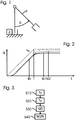
- Fig. 1 shows a bipartite robot 1 with a vertically rotatable hull, an arm rotatable about the horizontal and an implemented in the controller 2 of the robot 1 not shown test device according to an embodiment of the present invention for carrying out the closer in the following with reference to Fig. 3 described method.
- the joint angle q of the arm against the vertical describes the position of the robot 1 sufficiently for the following explanations.
- a brake test method the operation of which is described in Fig. 3 is sketched, the brake acting on the axis of rotation of the arm brake (not shown) is closed in a step S20 at time tb.
- This is formed in the embodiment as a mechanical, electromagnetically released jaw brake, the jaws act on the rotor of the drive designed as an electric motor arm axis and exert a direction of movement opposite service brake torque ⁇ B on this.
- This is slightly speed-dependent in the rotating rotor, but can be considered simplified as a constant and is in any case due to the comparison with the coefficient of static friction ⁇ 0 smaller sliding friction coefficient ⁇ between the jaw and rotor less than a maximum alsbringbares by the brake holding torque.
- both the time ts to standstill and the thereby achieved position q (ts) thus represent, as well as, for example, the occurring delay d 2 q / dt 2 a measure of the quality of the brake, in particular its function as a service brake in step S30, the joint angle q (t) of the arm is recorded and in a step S40 the brake is evaluated on the basis of this detected movement.
- a minimum time to be reached during this test is divided by the time ts0 reached until standstill ts0.
- This rating is recorded along with the temperature and time of the test and the test is repeated at predetermined time intervals. For example, lie between the in Fig. 2 Checks shown in full and dashed lines 200 days of normal operation of the robot 1, it can be extrapolated that the brake will no longer be functional after a further 300 days of normal operation.
Landscapes
- Physics & Mathematics (AREA)
- General Physics & Mathematics (AREA)
- Manipulator (AREA)
Claims (14)
- Procédé de contrôle d'un frein d'un manipulateur, en particulier d'un robot (1), avec les étapes de :- application d'une force d'entraînement prédéfinie (τA) sur le manipulateur (S10) ;- fermeture du frein (S20) ;- détection du déplacement (q ; dq/dt ; d2q/dt2) du manipulateur (S30) ; et- évaluation du frein sur la base du déplacement détecté (S40).
- Procédé selon la revendication 1, caractérisé en ce que la force d'entraînement appliquée sur le manipulateur est prédéfinie de sorte que le manipulateur modifie son sens de déplacement et/ou sa vitesse de déplacement pendant le contrôle.
- Procédé selon l'une quelconque des revendications précédentes, caractérisé en ce que la force d'entraînement appliquée sur le manipulateur correspond sensiblement à une force de contrôle du frein, en particulier à une force de service minimum du frein multipliée par un facteur de sécurité.
- Procédé selon l'une quelconque des revendications précédentes, caractérisé en ce que le frein est fermé une ou plusieurs fois et ensuite à nouveau ouvert, pendant que le déplacement du manipulateur est détecté.
- Procédé selon l'une quelconque des revendications précédentes, caractérisé en ce que pendant que la force d'entraînement prédéfinie est appliquée sur le manipulateur, le frein est fermé complètement ou incomplètement, en particulier sensiblement à 25 %, 50 %, 75 % et/ou 100 %, dans lequel 0 % correspond à un frein entièrement desserré et 100 % à un frein serré.
- Procédé selon l'une quelconque des revendications précédentes, caractérisé en ce que pour la détection du déplacement du manipulateur, sa position (q), sa vitesse (dq/dt) et/ou son accélération (d2q/dt2) est détectée.
- Procédé selon l'une quelconque des revendications précédentes, caractérisé en ce que le frein est évalué sur la base du déplacement détecté, par le fait qu'une grandeur décrivant le déplacement, en particulier la position, la vitesse et/ou l'accélération du manipulateur est comparée avec une valeur limite.
- Procédé selon l'une quelconque des revendications précédentes, caractérisé en ce qu'une force de freinage (τB) appliquée sur le manipulateur par le frein est déterminée sur la base du déplacement détecté et comparée avec une valeur limite.
- Procédé selon l'une quelconque des revendications précédentes 7 à 8, caractérisé en ce que la valeur limite correspond à une grandeur de consigne pour le frein multipliée par un facteur de sécurité ou à une valeur de référence.
- Procédé selon l'une quelconque des revendications précédentes, caractérisé en ce qu'il est répété à des intervalles de temps prédéfinis, et les évaluations ainsi obtenues du frein, en particulier avec des paramètres d'état pendant l'évaluation, sont enregistrées.
- Procédé selon l'une quelconque des revendications précédentes, caractérisé en ce que plusieurs freins du manipulateur sont fermés l'un après l'autre ou simultanément, pendant que des forces d'entraînement prédéfinies (τA) sont appliquées sur le manipulateur et ses déplacements détectés.
- Dispositif de contrôle pour un manipulateur, en particulier un robot (1), avec :une commande d'entraînement pour l'application d'une force d'entraînement prédéfinie (τA) sur le manipulateur ;une commande de frein ;un dispositif de détection pour la détection du déplacement (q ; dq/dt ; d2q/dt2) du manipulateur;caractérisé en ce quele dispositif de contrôle est aménagé pour la réalisation d'un procédé selon l'une quelconque des revendications précédentes.
- Programme informatique, qui exécute un procédé selon l'une quelconque des revendications 1 à 11, lorsqu'il se déroule dans un dispositif de contrôle selon la revendication 12.
- Produit de programme informatique avec code de programme, qui est enregistré sur un support lisible par machine et comprend un programme informatique selon la revendication 13.
Applications Claiming Priority (1)
| Application Number | Priority Date | Filing Date | Title |
|---|---|---|---|
| DE102008015949A DE102008015949A1 (de) | 2008-03-27 | 2008-03-27 | Prüfverfahren und -vorrichtung für eine Manipulatorbremse |
Publications (3)
| Publication Number | Publication Date |
|---|---|
| EP2108933A2 EP2108933A2 (fr) | 2009-10-14 |
| EP2108933A3 EP2108933A3 (fr) | 2017-09-20 |
| EP2108933B1 true EP2108933B1 (fr) | 2018-06-20 |
Family
ID=40957834
Family Applications (1)
| Application Number | Title | Priority Date | Filing Date |
|---|---|---|---|
| EP09003843.1A Active EP2108933B1 (fr) | 2008-03-27 | 2009-03-17 | Procédé et dispositif de contrôle pour un frein de manipulateur |
Country Status (2)
| Country | Link |
|---|---|
| EP (1) | EP2108933B1 (fr) |
| DE (1) | DE102008015949A1 (fr) |
Families Citing this family (11)
| Publication number | Priority date | Publication date | Assignee | Title |
|---|---|---|---|---|
| DE102010011788A1 (de) * | 2010-03-17 | 2011-09-22 | Sew-Eurodrive Gmbh & Co. Kg | Verfahren zum Betreiben eines Antriebssystem und Antriebssystem |
| JP5444421B2 (ja) * | 2012-06-28 | 2014-03-19 | ファナック株式会社 | ブレーキ異常診断方法およびブレーキ異常診断装置 |
| DE102014001923A1 (de) * | 2014-02-12 | 2015-08-13 | Kuka Roboter Gmbh | Verfahren und Vorrichtung zum Festlegen einer Manipulatorachse |
| EP2993000B1 (fr) | 2014-09-04 | 2019-05-15 | ABB Schweiz AG | Évaluation du couple de freinage dynamique dans un robot |
| EP3001164B1 (fr) | 2014-09-25 | 2019-03-27 | ABB Schweiz AG | Évaluation du couple de freinage statique dans un robot |
| DE102015001203A1 (de) | 2015-01-30 | 2016-08-04 | Kuka Roboter Gmbh | Verfahren und System zum Betreiben und/oder Überwachen einer mehrachsigen Maschine |
| EP3144654A1 (fr) * | 2015-09-18 | 2017-03-22 | Siemens Aktiengesellschaft | Procede de test de freinage destine a la verification de fonctionnement d'un frein de stationnement pour un moteur electrique dans un systeme d'entrainement electrique |
| CN112888532A (zh) * | 2018-10-12 | 2021-06-01 | Abb瑞士股份有限公司 | 用于确定动态摩擦力矩的方法和控制系统以及工业机器人 |
| DE102020205322A1 (de) * | 2020-04-27 | 2021-10-28 | Kuka Deutschland Gmbh | Verfahren zum automatischen Planen der zeitlichen Ausführung von Bremsentests und zugehöriger Roboter |
| DE102024112830A1 (de) | 2023-06-02 | 2024-12-05 | Sew-Eurodrive Gmbh & Co Kg | Verfahren zum Bestimmen und/oder Überwachen eines Getriebespiels und/oder des Verschleißzustandes eines Antriebs |
| DE102023115745A1 (de) * | 2023-06-15 | 2024-12-19 | Tox Pressotechnik Gmbh & Co. Kg | Vorrichtung mit einer Antriebseinheit und Verfahren |
Citations (6)
| Publication number | Priority date | Publication date | Assignee | Title |
|---|---|---|---|---|
| DE19756752A1 (de) | 1997-12-19 | 1999-06-24 | Heidenhain Gmbh Dr Johannes | Verfahren und Schaltungsanordnung zur Überprüfung von Motorbremsen |
| EP1215475A2 (fr) | 2000-12-13 | 2002-06-19 | KUKA Roboter GmbH | Méthode pour tester le frein d'un moteur électrique |
| EP1239354A1 (fr) | 1997-12-06 | 2002-09-11 | Elan Schaltelemente GmbH & Co. KG | Procédé de surveillance d'un dispositif de freinage, en particulier un appareil de manipulation, ainsi qu'un appareil de commande et de surveillance |
| DE102005015608A1 (de) | 2005-04-05 | 2006-10-12 | Motoman Robotec Gmbh | Verfahren zum Prüfen der Bremse eines Motors eines Roboters |
| WO2007079950A1 (fr) | 2006-01-10 | 2007-07-19 | Abb Technology Ag | Procédé pour contrôler une fonction de freinage d'un moteur de robot |
| WO2007131712A1 (fr) | 2006-05-15 | 2007-11-22 | Kuka Roboter Gmbh | Robot articulé à éléments fonctionnels redondants |
Family Cites Families (1)
| Publication number | Priority date | Publication date | Assignee | Title |
|---|---|---|---|---|
| DE102005037189A1 (de) * | 2005-08-06 | 2007-02-08 | Reis Gmbh & Co. Kg Maschinenfabrik | Verfahren und Schaltungsanordnung zur sicheren Zustandsüberwachung einer Antriebseinheit mit Mehrphasenmotor |
-
2008
- 2008-03-27 DE DE102008015949A patent/DE102008015949A1/de not_active Ceased
-
2009
- 2009-03-17 EP EP09003843.1A patent/EP2108933B1/fr active Active
Patent Citations (6)
| Publication number | Priority date | Publication date | Assignee | Title |
|---|---|---|---|---|
| EP1239354A1 (fr) | 1997-12-06 | 2002-09-11 | Elan Schaltelemente GmbH & Co. KG | Procédé de surveillance d'un dispositif de freinage, en particulier un appareil de manipulation, ainsi qu'un appareil de commande et de surveillance |
| DE19756752A1 (de) | 1997-12-19 | 1999-06-24 | Heidenhain Gmbh Dr Johannes | Verfahren und Schaltungsanordnung zur Überprüfung von Motorbremsen |
| EP1215475A2 (fr) | 2000-12-13 | 2002-06-19 | KUKA Roboter GmbH | Méthode pour tester le frein d'un moteur électrique |
| DE102005015608A1 (de) | 2005-04-05 | 2006-10-12 | Motoman Robotec Gmbh | Verfahren zum Prüfen der Bremse eines Motors eines Roboters |
| WO2007079950A1 (fr) | 2006-01-10 | 2007-07-19 | Abb Technology Ag | Procédé pour contrôler une fonction de freinage d'un moteur de robot |
| WO2007131712A1 (fr) | 2006-05-15 | 2007-11-22 | Kuka Roboter Gmbh | Robot articulé à éléments fonctionnels redondants |
Also Published As
| Publication number | Publication date |
|---|---|
| EP2108933A3 (fr) | 2017-09-20 |
| EP2108933A2 (fr) | 2009-10-14 |
| DE102008015949A1 (de) | 2009-10-08 |
Similar Documents
| Publication | Publication Date | Title |
|---|---|---|
| EP2108933B1 (fr) | Procédé et dispositif de contrôle pour un frein de manipulateur | |
| EP2829365B1 (fr) | Procédé et dispositif destinés au freinage d'un système d'axe de robot | |
| DE102017005043B4 (de) | Vorrichtung und Verfahren zum Erkennen einer Abnormalität eines Gelenks eines Parallelarmroboters | |
| DE102010044644B4 (de) | Verfahren zur Kollisionserkennung für eine Antriebseinheit | |
| EP3050682B1 (fr) | Procédé et système de fonctionnement et/ou de surveillance d'une machine multiaxiale | |
| DE102012220037B4 (de) | Passiv betätigtes Bremssystem | |
| EP2347309B1 (fr) | Procédé et dispositif pour la détection fiable d'une grandeur cinématique d'un manipulateur | |
| AT514887B1 (de) | Schwenkschiebetürmodul mit sensorisch überwachter Übertotpunktverriegelung und Betriebsverfahren hierfür | |
| EP3078460B1 (fr) | Procede de commande d'au moins un manipulateur a l'aide d'au moins un dispositif d'equilibrage des forces | |
| DE102017008916A1 (de) | Produktionssystem zum Ausführen von kooperativer Arbeit durch eine Bedienperson und einen Roboter | |
| DE102013020697B4 (de) | Verfahren und Steuermittel zum Steuern eines Roboters | |
| EP3131710A1 (fr) | Dispositif robot présentant un axe linéaire | |
| DE102013013875A1 (de) | Verfahren zum Steuern eines Roboters | |
| DE4217587C2 (de) | Anlagen-Diagnoseverfahren | |
| DE102016014989B4 (de) | Kollisionsüberwachung eines Roboters | |
| EP2899091B1 (fr) | Module de porte oscillante coulissante doté d'un verrouillage décentré surveillé et son procédé de fonctionnement | |
| DE102019102470A1 (de) | Einlernvorgang für ein Robotersystem bestehend aus zwei Robotermanipulatoren | |
| DE102015008740B4 (de) | Robotersteuerungsvorrichtung, die in der lage ist, ein werkstück mit einem parameter zu befördern, der einen soll-werkstückparatmeter überschreitet | |
| EP3215449B1 (fr) | Ascenseur équipé d'un dispositif de freinage | |
| WO2010066318A1 (fr) | Procédé et dispositif de commande d'un système de manipulateur | |
| EP3492329A1 (fr) | Procédé de fonctionnement d'un véhicule automobile ainsi que véhicule automobile correspondant | |
| EP1806837B1 (fr) | Méthode pour tester la fonction de freinage d'un entraînement du robot | |
| EP3233395A1 (fr) | Procédé et dispositif de commande d'un système d'entraînement pour mettre en mouvement un outil, notamment guidé par un robot | |
| EP2126536B1 (fr) | Dispositif et procédé pour un test de fonctionnement d'un frein | |
| EP1750188B1 (fr) | Procédé et dispositif de couplage destinés à la surveillance d'état sécurisée d'une unité d'entraînement munie d'un moteur polyphasé |
Legal Events
| Date | Code | Title | Description |
|---|---|---|---|
| PUAI | Public reference made under article 153(3) epc to a published international application that has entered the european phase |
Free format text: ORIGINAL CODE: 0009012 |
|
| AK | Designated contracting states |
Kind code of ref document: A2 Designated state(s): AT BE BG CH CY CZ DE DK EE ES FI FR GB GR HR HU IE IS IT LI LT LU LV MC MK MT NL NO PL PT RO SE SI SK TR |
|
| AX | Request for extension of the european patent |
Extension state: AL BA RS |
|
| RAP1 | Party data changed (applicant data changed or rights of an application transferred) |
Owner name: KUKA LABORATORIES GMBH |
|
| RAP1 | Party data changed (applicant data changed or rights of an application transferred) |
Owner name: KUKA ROBOTER GMBH |
|
| PUAL | Search report despatched |
Free format text: ORIGINAL CODE: 0009013 |
|
| AK | Designated contracting states |
Kind code of ref document: A3 Designated state(s): AT BE BG CH CY CZ DE DK EE ES FI FR GB GR HR HU IE IS IT LI LT LU LV MC MK MT NL NO PL PT RO SE SI SK TR |
|
| AX | Request for extension of the european patent |
Extension state: AL BA RS |
|
| RIC1 | Information provided on ipc code assigned before grant |
Ipc: G01L 5/28 20060101AFI20170814BHEP |
|
| STAA | Information on the status of an ep patent application or granted ep patent |
Free format text: STATUS: REQUEST FOR EXAMINATION WAS MADE |
|
| GRAP | Despatch of communication of intention to grant a patent |
Free format text: ORIGINAL CODE: EPIDOSNIGR1 |
|
| STAA | Information on the status of an ep patent application or granted ep patent |
Free format text: STATUS: GRANT OF PATENT IS INTENDED |
|
| 17P | Request for examination filed |
Effective date: 20180228 |
|
| RBV | Designated contracting states (corrected) |
Designated state(s): AT BE BG CH CY CZ DE DK EE ES FI FR GB GR HR HU IE IS IT LI LT LU LV MC MK MT NL NO PL PT RO SE SI SK TR |
|
| INTG | Intention to grant announced |
Effective date: 20180406 |
|
| GRAS | Grant fee paid |
Free format text: ORIGINAL CODE: EPIDOSNIGR3 |
|
| GRAA | (expected) grant |
Free format text: ORIGINAL CODE: 0009210 |
|
| STAA | Information on the status of an ep patent application or granted ep patent |
Free format text: STATUS: THE PATENT HAS BEEN GRANTED |
|
| AKX | Designation fees paid |
Designated state(s): AT BE BG CH CY CZ DE DK EE ES FI FR GB GR HR HU IE IS IT LI LT LU LV MC MK MT NL NO PL PT RO SE SI SK TR |
|
| AXX | Extension fees paid |
Extension state: BA Extension state: AL Extension state: RS |
|
| AK | Designated contracting states |
Kind code of ref document: B1 Designated state(s): AT BE BG CH CY CZ DE DK EE ES FI FR GB GR HR HU IE IS IT LI LT LU LV MC MK MT NL NO PL PT RO SE SI SK TR |
|
| RAP1 | Party data changed (applicant data changed or rights of an application transferred) |
Owner name: KUKA DEUTSCHLAND GMBH |
|
| REG | Reference to a national code |
Ref country code: GB Ref legal event code: FG4D Free format text: NOT ENGLISH |
|
| REG | Reference to a national code |
Ref country code: IE Ref legal event code: FG4D Free format text: LANGUAGE OF EP DOCUMENT: GERMAN |
|
| REG | Reference to a national code |
Ref country code: DE Ref legal event code: R096 Ref document number: 502009015033 Country of ref document: DE |
|
| REG | Reference to a national code |
Ref country code: AT Ref legal event code: REF Ref document number: 1010945 Country of ref document: AT Kind code of ref document: T Effective date: 20180715 |
|
| REG | Reference to a national code |
Ref country code: NL Ref legal event code: MP Effective date: 20180620 |
|
| PG25 | Lapsed in a contracting state [announced via postgrant information from national office to epo] |
Ref country code: SE Free format text: LAPSE BECAUSE OF FAILURE TO SUBMIT A TRANSLATION OF THE DESCRIPTION OR TO PAY THE FEE WITHIN THE PRESCRIBED TIME-LIMIT Effective date: 20180620 Ref country code: LT Free format text: LAPSE BECAUSE OF FAILURE TO SUBMIT A TRANSLATION OF THE DESCRIPTION OR TO PAY THE FEE WITHIN THE PRESCRIBED TIME-LIMIT Effective date: 20180620 Ref country code: FI Free format text: LAPSE BECAUSE OF FAILURE TO SUBMIT A TRANSLATION OF THE DESCRIPTION OR TO PAY THE FEE WITHIN THE PRESCRIBED TIME-LIMIT Effective date: 20180620 Ref country code: NO Free format text: LAPSE BECAUSE OF FAILURE TO SUBMIT A TRANSLATION OF THE DESCRIPTION OR TO PAY THE FEE WITHIN THE PRESCRIBED TIME-LIMIT Effective date: 20180920 Ref country code: BG Free format text: LAPSE BECAUSE OF FAILURE TO SUBMIT A TRANSLATION OF THE DESCRIPTION OR TO PAY THE FEE WITHIN THE PRESCRIBED TIME-LIMIT Effective date: 20180920 |
|
| REG | Reference to a national code |
Ref country code: LT Ref legal event code: MG4D |
|
| PG25 | Lapsed in a contracting state [announced via postgrant information from national office to epo] |
Ref country code: GR Free format text: LAPSE BECAUSE OF FAILURE TO SUBMIT A TRANSLATION OF THE DESCRIPTION OR TO PAY THE FEE WITHIN THE PRESCRIBED TIME-LIMIT Effective date: 20180921 Ref country code: LV Free format text: LAPSE BECAUSE OF FAILURE TO SUBMIT A TRANSLATION OF THE DESCRIPTION OR TO PAY THE FEE WITHIN THE PRESCRIBED TIME-LIMIT Effective date: 20180620 Ref country code: HR Free format text: LAPSE BECAUSE OF FAILURE TO SUBMIT A TRANSLATION OF THE DESCRIPTION OR TO PAY THE FEE WITHIN THE PRESCRIBED TIME-LIMIT Effective date: 20180620 |
|
| PG25 | Lapsed in a contracting state [announced via postgrant information from national office to epo] |
Ref country code: NL Free format text: LAPSE BECAUSE OF FAILURE TO SUBMIT A TRANSLATION OF THE DESCRIPTION OR TO PAY THE FEE WITHIN THE PRESCRIBED TIME-LIMIT Effective date: 20180620 |
|
| PG25 | Lapsed in a contracting state [announced via postgrant information from national office to epo] |
Ref country code: SK Free format text: LAPSE BECAUSE OF FAILURE TO SUBMIT A TRANSLATION OF THE DESCRIPTION OR TO PAY THE FEE WITHIN THE PRESCRIBED TIME-LIMIT Effective date: 20180620 Ref country code: PL Free format text: LAPSE BECAUSE OF FAILURE TO SUBMIT A TRANSLATION OF THE DESCRIPTION OR TO PAY THE FEE WITHIN THE PRESCRIBED TIME-LIMIT Effective date: 20180620 Ref country code: EE Free format text: LAPSE BECAUSE OF FAILURE TO SUBMIT A TRANSLATION OF THE DESCRIPTION OR TO PAY THE FEE WITHIN THE PRESCRIBED TIME-LIMIT Effective date: 20180620 Ref country code: IS Free format text: LAPSE BECAUSE OF FAILURE TO SUBMIT A TRANSLATION OF THE DESCRIPTION OR TO PAY THE FEE WITHIN THE PRESCRIBED TIME-LIMIT Effective date: 20181020 Ref country code: CZ Free format text: LAPSE BECAUSE OF FAILURE TO SUBMIT A TRANSLATION OF THE DESCRIPTION OR TO PAY THE FEE WITHIN THE PRESCRIBED TIME-LIMIT Effective date: 20180620 Ref country code: RO Free format text: LAPSE BECAUSE OF FAILURE TO SUBMIT A TRANSLATION OF THE DESCRIPTION OR TO PAY THE FEE WITHIN THE PRESCRIBED TIME-LIMIT Effective date: 20180620 |
|
| PG25 | Lapsed in a contracting state [announced via postgrant information from national office to epo] |
Ref country code: ES Free format text: LAPSE BECAUSE OF FAILURE TO SUBMIT A TRANSLATION OF THE DESCRIPTION OR TO PAY THE FEE WITHIN THE PRESCRIBED TIME-LIMIT Effective date: 20180620 Ref country code: IT Free format text: LAPSE BECAUSE OF FAILURE TO SUBMIT A TRANSLATION OF THE DESCRIPTION OR TO PAY THE FEE WITHIN THE PRESCRIBED TIME-LIMIT Effective date: 20180620 |
|
| REG | Reference to a national code |
Ref country code: DE Ref legal event code: R026 Ref document number: 502009015033 Country of ref document: DE |
|
| PLBI | Opposition filed |
Free format text: ORIGINAL CODE: 0009260 |
|
| PLAX | Notice of opposition and request to file observation + time limit sent |
Free format text: ORIGINAL CODE: EPIDOSNOBS2 |
|
| 26 | Opposition filed |
Opponent name: FRANKA EMIKA GMBH Effective date: 20190320 |
|
| PLAB | Opposition data, opponent's data or that of the opponent's representative modified |
Free format text: ORIGINAL CODE: 0009299OPPO |
|
| R26 | Opposition filed (corrected) |
Opponent name: FRANKA EMIKA GMBH Effective date: 20190320 |
|
| PG25 | Lapsed in a contracting state [announced via postgrant information from national office to epo] |
Ref country code: DK Free format text: LAPSE BECAUSE OF FAILURE TO SUBMIT A TRANSLATION OF THE DESCRIPTION OR TO PAY THE FEE WITHIN THE PRESCRIBED TIME-LIMIT Effective date: 20180620 |
|
| PLBB | Reply of patent proprietor to notice(s) of opposition received |
Free format text: ORIGINAL CODE: EPIDOSNOBS3 |
|
| PG25 | Lapsed in a contracting state [announced via postgrant information from national office to epo] |
Ref country code: SI Free format text: LAPSE BECAUSE OF FAILURE TO SUBMIT A TRANSLATION OF THE DESCRIPTION OR TO PAY THE FEE WITHIN THE PRESCRIBED TIME-LIMIT Effective date: 20180620 |
|
| PG25 | Lapsed in a contracting state [announced via postgrant information from national office to epo] |
Ref country code: MC Free format text: LAPSE BECAUSE OF FAILURE TO SUBMIT A TRANSLATION OF THE DESCRIPTION OR TO PAY THE FEE WITHIN THE PRESCRIBED TIME-LIMIT Effective date: 20180620 |
|
| PG25 | Lapsed in a contracting state [announced via postgrant information from national office to epo] |
Ref country code: LU Free format text: LAPSE BECAUSE OF NON-PAYMENT OF DUE FEES Effective date: 20190317 |
|
| REG | Reference to a national code |
Ref country code: BE Ref legal event code: MM Effective date: 20190331 |
|
| PG25 | Lapsed in a contracting state [announced via postgrant information from national office to epo] |
Ref country code: IE Free format text: LAPSE BECAUSE OF NON-PAYMENT OF DUE FEES Effective date: 20190317 |
|
| PG25 | Lapsed in a contracting state [announced via postgrant information from national office to epo] |
Ref country code: BE Free format text: LAPSE BECAUSE OF NON-PAYMENT OF DUE FEES Effective date: 20190331 |
|
| PG25 | Lapsed in a contracting state [announced via postgrant information from national office to epo] |
Ref country code: TR Free format text: LAPSE BECAUSE OF FAILURE TO SUBMIT A TRANSLATION OF THE DESCRIPTION OR TO PAY THE FEE WITHIN THE PRESCRIBED TIME-LIMIT Effective date: 20180620 |
|
| PG25 | Lapsed in a contracting state [announced via postgrant information from national office to epo] |
Ref country code: PT Free format text: LAPSE BECAUSE OF FAILURE TO SUBMIT A TRANSLATION OF THE DESCRIPTION OR TO PAY THE FEE WITHIN THE PRESCRIBED TIME-LIMIT Effective date: 20181022 Ref country code: MT Free format text: LAPSE BECAUSE OF FAILURE TO SUBMIT A TRANSLATION OF THE DESCRIPTION OR TO PAY THE FEE WITHIN THE PRESCRIBED TIME-LIMIT Effective date: 20180620 |
|
| REG | Reference to a national code |
Ref country code: AT Ref legal event code: MM01 Ref document number: 1010945 Country of ref document: AT Kind code of ref document: T Effective date: 20190317 |
|
| PG25 | Lapsed in a contracting state [announced via postgrant information from national office to epo] |
Ref country code: AT Free format text: LAPSE BECAUSE OF NON-PAYMENT OF DUE FEES Effective date: 20190317 |
|
| PLCK | Communication despatched that opposition was rejected |
Free format text: ORIGINAL CODE: EPIDOSNREJ1 |
|
| REG | Reference to a national code |
Ref country code: DE Ref legal event code: R100 Ref document number: 502009015033 Country of ref document: DE |
|
| PLBN | Opposition rejected |
Free format text: ORIGINAL CODE: 0009273 |
|
| STAA | Information on the status of an ep patent application or granted ep patent |
Free format text: STATUS: OPPOSITION REJECTED |
|
| 27O | Opposition rejected |
Effective date: 20201221 |
|
| PG25 | Lapsed in a contracting state [announced via postgrant information from national office to epo] |
Ref country code: CY Free format text: LAPSE BECAUSE OF FAILURE TO SUBMIT A TRANSLATION OF THE DESCRIPTION OR TO PAY THE FEE WITHIN THE PRESCRIBED TIME-LIMIT Effective date: 20180620 |
|
| PG25 | Lapsed in a contracting state [announced via postgrant information from national office to epo] |
Ref country code: HU Free format text: LAPSE BECAUSE OF FAILURE TO SUBMIT A TRANSLATION OF THE DESCRIPTION OR TO PAY THE FEE WITHIN THE PRESCRIBED TIME-LIMIT; INVALID AB INITIO Effective date: 20090317 |
|
| PG25 | Lapsed in a contracting state [announced via postgrant information from national office to epo] |
Ref country code: MK Free format text: LAPSE BECAUSE OF FAILURE TO SUBMIT A TRANSLATION OF THE DESCRIPTION OR TO PAY THE FEE WITHIN THE PRESCRIBED TIME-LIMIT Effective date: 20180620 |
|
| P01 | Opt-out of the competence of the unified patent court (upc) registered |
Effective date: 20230528 |
|
| PGFP | Annual fee paid to national office [announced via postgrant information from national office to epo] |
Ref country code: DE Payment date: 20241231 Year of fee payment: 17 |
|
| PGFP | Annual fee paid to national office [announced via postgrant information from national office to epo] |
Ref country code: FR Payment date: 20250108 Year of fee payment: 17 |
|
| PGFP | Annual fee paid to national office [announced via postgrant information from national office to epo] |
Ref country code: GB Payment date: 20250102 Year of fee payment: 17 |
|
| PGFP | Annual fee paid to national office [announced via postgrant information from national office to epo] |
Ref country code: CH Payment date: 20250401 Year of fee payment: 17 |