EP2108964A2 - Systèmes et procédés de détermination d'accélération et de rotation à partir d'un dispositif mems dans le plan et hors du plan - Google Patents
Systèmes et procédés de détermination d'accélération et de rotation à partir d'un dispositif mems dans le plan et hors du plan Download PDFInfo
- Publication number
- EP2108964A2 EP2108964A2 EP09156312A EP09156312A EP2108964A2 EP 2108964 A2 EP2108964 A2 EP 2108964A2 EP 09156312 A EP09156312 A EP 09156312A EP 09156312 A EP09156312 A EP 09156312A EP 2108964 A2 EP2108964 A2 EP 2108964A2
- Authority
- EP
- European Patent Office
- Prior art keywords
- plane
- proof mass
- sense
- comb
- sensing
- Prior art date
- Legal status (The legal status is an assumption and is not a legal conclusion. Google has not performed a legal analysis and makes no representation as to the accuracy of the status listed.)
- Granted
Links
- 230000001133 acceleration Effects 0.000 title claims abstract description 80
- 238000000034 method Methods 0.000 title claims abstract description 17
- 230000033001 locomotion Effects 0.000 claims description 57
- 238000012545 processing Methods 0.000 claims description 18
- 230000003534 oscillatory effect Effects 0.000 claims 4
- 239000000758 substrate Substances 0.000 description 13
- 230000008859 change Effects 0.000 description 11
- 210000001520 comb Anatomy 0.000 description 10
- 239000013598 vector Substances 0.000 description 9
- 238000005259 measurement Methods 0.000 description 7
- XUIMIQQOPSSXEZ-UHFFFAOYSA-N Silicon Chemical compound [Si] XUIMIQQOPSSXEZ-UHFFFAOYSA-N 0.000 description 4
- 230000001419 dependent effect Effects 0.000 description 4
- 238000004519 manufacturing process Methods 0.000 description 4
- 230000003071 parasitic effect Effects 0.000 description 4
- 230000008569 process Effects 0.000 description 4
- 238000000926 separation method Methods 0.000 description 4
- 238000013461 design Methods 0.000 description 3
- 238000010586 diagram Methods 0.000 description 3
- 230000004044 response Effects 0.000 description 3
- 238000001514 detection method Methods 0.000 description 2
- 229910052710 silicon Inorganic materials 0.000 description 2
- 239000010703 silicon Substances 0.000 description 2
- 238000010276 construction Methods 0.000 description 1
- 230000001808 coupling effect Effects 0.000 description 1
- 239000011521 glass Substances 0.000 description 1
- 239000002184 metal Substances 0.000 description 1
- 230000009467 reduction Effects 0.000 description 1
- 238000012360 testing method Methods 0.000 description 1
Images




Classifications
-
- G—PHYSICS
- G01—MEASURING; TESTING
- G01P—MEASURING LINEAR OR ANGULAR SPEED, ACCELERATION, DECELERATION, OR SHOCK; INDICATING PRESENCE, ABSENCE, OR DIRECTION, OF MOVEMENT
- G01P15/00—Measuring acceleration; Measuring deceleration; Measuring shock, i.e. sudden change of acceleration
- G01P15/18—Measuring acceleration; Measuring deceleration; Measuring shock, i.e. sudden change of acceleration in two or more dimensions
-
- G—PHYSICS
- G01—MEASURING; TESTING
- G01C—MEASURING DISTANCES, LEVELS OR BEARINGS; SURVEYING; NAVIGATION; GYROSCOPIC INSTRUMENTS; PHOTOGRAMMETRY OR VIDEOGRAMMETRY
- G01C19/00—Gyroscopes; Turn-sensitive devices using vibrating masses; Turn-sensitive devices without moving masses; Measuring angular rate using gyroscopic effects
- G01C19/56—Turn-sensitive devices using vibrating masses, e.g. vibratory angular rate sensors based on Coriolis forces
- G01C19/5719—Turn-sensitive devices using vibrating masses, e.g. vibratory angular rate sensors based on Coriolis forces using planar vibrating masses driven in a translation vibration along an axis
-
- G—PHYSICS
- G01—MEASURING; TESTING
- G01P—MEASURING LINEAR OR ANGULAR SPEED, ACCELERATION, DECELERATION, OR SHOCK; INDICATING PRESENCE, ABSENCE, OR DIRECTION, OF MOVEMENT
- G01P15/00—Measuring acceleration; Measuring deceleration; Measuring shock, i.e. sudden change of acceleration
- G01P15/02—Measuring acceleration; Measuring deceleration; Measuring shock, i.e. sudden change of acceleration by making use of inertia forces using solid seismic masses
- G01P15/08—Measuring acceleration; Measuring deceleration; Measuring shock, i.e. sudden change of acceleration by making use of inertia forces using solid seismic masses with conversion into electric or magnetic values
- G01P15/125—Measuring acceleration; Measuring deceleration; Measuring shock, i.e. sudden change of acceleration by making use of inertia forces using solid seismic masses with conversion into electric or magnetic values by capacitive pick-up
Definitions
- Micro-Electro-Mechanical Systems (MEMS) inertial measurement units contain three gyroscopes and three accelerometers for detecting changes in attitude and acceleration.
- the three gyroscopes and the three accelerometers are mounted on separate orthogonal axes, each with their own set of control and read-out electronics.
- the three gyroscopes and the three accelerometers must be precisely installed, in view that a relatively large amount of processing capacity is required to process information from six separate units, and in view of the power source requirements to power the three gyroscopes and the three accelerometers.
- Many applications require a reduction in size, computational requirements, power requirements, and cost of a MEMS inertial measurement unit. In view of these constraints, it would be advantageous to reduce the number of sensing devices in a MEMS inertial measurement unit.
- a conventional MEMS gyroscope may be used to determine angular rotation by measuring Coriolis forces exerted on resonating proof masses.
- a conventional MEMS gyroscope includes two silicon proof masses mechanically coupled to and suspended from a substrate, typically glass, using one or more silicon flexures. A number of recesses etched into the substrate allow selective portions of the silicon structure to move back and forth freely within an interior portion of the device.
- substrates can be provided above and below the silicon structure to sandwich the proof masses between the two substrates.
- a pattern of metal traces formed on the substrate(s) can be used to deliver various electrical bias voltages and signal outputs to the device.
- a drive system for many MEMS gyroscopes typically includes a number of drive elements that cause the proof mass to oscillate back and forth along a drive axis perpendicular to the direction in which Coriolis forces are sensed.
- the drive elements may include a number of interdigitated vertical comb fingers, or tines, configured to convert electrical energy into mechanical energy using electrostatic actuation.
- Such drive elements are described, for example, in U.S. Pat. No. 5,025,346 to Tang et al. , entitled “LATERALLY DRIVEN RESONANT MICROSTRUCTURES," and U.S. Pat. No.
- MEMS GYROSCOPE WITH HORIZONTALLY ORIENTED DRIVE ELECTRODES both of which are incorporated herein by reference in their entirety.
- MEMS devices are operated in an open loop mode wherein the acceleration and rotation (gyro) responses are coupled with and depend on each other.
- MEMS Micro-Electro-Mechanical Systems
- An exemplary embodiment comprises a first proof mass and a second proof mass aligned in an in-plane axis, a first out-of-plane electrode pair with the first proof mass disposed therebetween, a second out-of plane electrode pair with the second proof mass disposed therebetween, a first in-plane sense comb with a plurality of comb fingers interleaved with opposing first proof mass comb fingers, and a second in-plane sense comb with a plurality of comb fingers interleaved with the opposing second proof mass comb fingers.
- An out-of-plane linear acceleration of the MEMS sensor may be sensed with the first out-of-plane electrode pair and the second out-of-plane electrode pair.
- An in-plane rotation of the MEMS sensor may be sensed with the first out-of-plane electrode pair and the second out-of-plane electrode.
- An in-plane linear acceleration of the MEMS sensor may be sensed with the first in-plane sense comb and the second in-plane sense comb.
- An out-of plane rotation of the MEMS sensor may be sensed with the first in-plane sense comb and the second in-plane sense comb.
- FIGURE 1 is a conceptual perspective view of an inertial sensor that is operable to sense linear acceleration and rotation in in-plane and in out-of-plane directions;
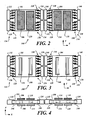
- FIGURE 2 is a top-down view of an exemplary embodiment of the inertial sensor
- FIGURE 3 is a top-down view of the exemplary embodiment of the inertial sensor illustrating the drive electrodes with combs interleaved with the two proof masses;
- FIGURE 4 is a side view of the exemplary embodiment of the inertial sensor
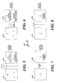
- FIGURE 5 is a conceptual view illustrating in-plane gyro sensing
- FIGURE 6 is a conceptual view illustrating out-of-plane gyro sensing
- FIGURE 7 is a conceptual view illustrating out-of-plane linear acceleration sensing
- FIGURE 8 is a conceptual view illustrating in-plane linear acceleration sensing
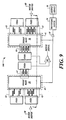
- FIGURE 9 illustrates a top-down view of a portion of the embodiment of the inertial sensor
- FIGURE 10 illustrates a partial cross sectional view of the system of FIGURE 9 ;
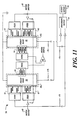
- FIGURE 11 illustrates another example system 70 for sensing rate of rotation about two separate axes
- FIGURE 12 is a conceptual side view of a portion of an embodiment of the inertial sensor
- FIGURE 13 is a conceptual side view of a portion of an embodiment of the inertial sensor with applied initialization rebalancing forces
- FIGURE 14 is a conceptual side view of a portion of an embodiment of the inertial sensor 100 with an applied linear acceleration
- FIGURE 15 is a conceptual side view of a portion of an embodiment of the inertial sensor 100 with an applied rotation
- FIGURE 16 illustrates applied and sensing voltages for a portion of an embodiment of the inertial sensor
- FIGURES 17-18 illustrate applied and sensing voltages for embodiments of the inertial sensor.
- FIGURE 19 is a block diagram illustrating an exemplary implementation of a digital signal processing system coupled to an embodiment of the inertial sensor.
- Embodiments of the inertial sensor 100 decouple acceleration sensing and rotation sensing so that rotation and acceleration are independently determinable.
- FIGURE 1 is a block diagram of a portion of an embodiment of an inertial sensor 100.
- the exemplary portion of the inertial sensor 100 is operable to sense either linear acceleration or rotation. Other portions of the inertial sensor 100 that sense rotation are described and illustrated below.
- the illustrated portion of the inertial sensor 100 comprises a first proof mass 102 (interchangeably referred to herein as the left proof mass 102) and a second proof mass 104 (interchangeably referred to herein as the right proof mass 104).
- the left proof mass 102 is between a first upper left sense (ULS) electrode 106 and a first lower left sense (LLS) electrode 108.
- the left proof mass 102 is also between a second ULS electrode 110 and a second LLS electrode 112.
- the right proof mass 104 is between an upper right sense (URS) electrode 114 and a lower right sense (LRS) electrode 116.
- the right proof mass 104 is also between a second URS electrode 118 and a second LRS electrode 120.
- the upper and lower sense electrodes are operable to sense out-of-plane motion of the inertial sensor 100.
- the left proof mass 102 is separated from the ULS electrodes 106, 110 by a gap (G ULS ) which defines capacitances that are dependent upon the separation distance between the left proof mass 102 and the ULS electrodes 106, 110.
- the left proof mass 102 is separated from the LLS electrodes 108, 112 by a gap (G LLS ) which defines capacitances that are dependent upon the separation distance between the left proof mass 102 and the LLS electrodes 108, 112. Changes in the capacitances associated with the gaps G ULS and G LLS , caused by an out-of-plane linear acceleration or an in-plane rotation are detectable.
- the right proof mass 104 is separated from the URS electrodes 114, 118 by a gap (G URS ) which defines capacitances that are dependent upon the separation distance between the right proof mass 104 and the URS electrodes 114, 118.
- the right proof mass 104 is separated from the LRS electrodes 116, 120 by a gap (G LRS ) which defines capacitances that are dependent upon the separation distance between the right proof mass 104 and the LRS electrodes 116, 120.
- Changes in the capacitances associated with the gaps G URS and G LRS caused by an out-of-plane linear acceleration or an in-plane rotational are detectable.
- the proof masses 102, 104 are capacitively coupled to drive electrodes (not shown in FIGURE 1 ) which impart a "back-and-forth" motion to the proof masses 102, 104 as an alternating current (AC) voltage is applied to the drive electrodes.
- the drive electrodes cause the proof masses 102, 104 to oscillate back and forth in resonance along a drive axis (the illustrated X-axis).
- the drive axis and the Y-axis define an in-plane motion of the proof masses 102, 104.
- the relative direction of motion of the left proof mass 102 is opposite from the direction of motion of the right proof mass 104, as denoted by the direction vector 122b, during one half cycle of the resonant motion.
- the proof masses 102, 104 are illustrated as moving away from each other in FIGURE 1 .
- the proof masses 102, 104 move towards each other.
- the proof masses 102, 104 oscillate with opposing motions that are 180° out of phase with each other. It is appreciated that embodiments of the inertial sensor 100 may be implemented in MEMS based devices having various configurations of drive electrodes.
- the inertial sensor 100 further includes at least one in-plane sense electrode 124 capacitively coupled to proof mass 102 and senses in-plane motion of proof mass 102. At least one in-plane sense electrode 126 is capacitively coupled to proof mass 104 and senses in-plane motion of proof mass 104.
- the in-plane sense electrodes 124, 126 interchangeably referred to herein as in-plane sense combs, include pairs of comb fingers 128 that are operable to sense motion of the proof masses 102, 104 in the Y-axis direction. Illustrated is a comb finger pair 128 with a comb finger of the in-plane sense electrode 124 and a comb finger of the proof mass 102 interleaved with each other.
- FIGURE 2 is a top-down view of an exemplary embodiment of the inertial sensor 100 illustrating the top ones of the out-of-plane paired sense electrodes 106 and 108, sense electrodes 110 and 112, sense electrodes 114 and 116, sense electrodes 118 and 120, and sense electrodes 124 and 126.
- four in-plane sense electrodes 130, 132, 134, and 136 are illustrated which correspond to the in-plane sense electrode 124 described above.
- the in-plane sense electrodes 130, 132, 134, and 136 have comb fingers interleaved with corresponding comb fingers of the proof mass 102 to form a plurality of comb finger pairs 128.
- the four in-plane sense electrodes 138, 140, 142, and 144 are illustrated which correspond to the in-plane sense electrode 126 described above.
- the in-plane sense electrodes 138, 140, 142, and 144 also have comb fingers interleaved with corresponding comb fingers of the proof mass 104 to form a plurality of comb finger pairs 128.
- the illustrated in-plane sense electrodes 130, 132, 134, 136, 138, 140, 142, and 144 conceptually illustrate only four comb finger pairs 128. In actual construction, the in-plane sense electrodes 130, 132, 134, 136, 138, 140, 142, and 144 would have many more comb finger pairs 128. Further, for conceptual illustration, the in-plane sense electrodes 130, 132, 134, 136, 138, 140, 142, and 144 are illustrated as relatively large electrodes.
- Various embodiments may have more than, or fewer than, the illustrated four in-plane sense electrodes 130, 132, 134, and 136 that are capacitively coupled to proof mass 102, and the four in-plane sense electrodes 138, 140, 142, and 144 that are capacitively coupled to proof mass 104. Furthermore, all of the various in-plane sense electrodes as fabricated may be relatively smaller than illustrated.
- embodiments of the inertial sensor 100 may have other sense electrodes, not shown in the FIGURES for brevity.
- pick-off sense electrodes may be included to sense motor motion induced in the proof masses 102, 104.
- FIGURE 3 is a top-down view of the exemplary embodiment of the inertial sensor 100 illustrating drive electrodes 146 which are interleaved with and capacitively coupled to combs of the proof mass 102.
- the drive electrodes 146 induce the above described motor motion to proof masses 102, 104.
- FIGURE 4 is a side view of the exemplary embodiment of the inertial sensor 100 illustrating the two proof masses 102, 104; the four out-of-plane electrode pairs each with an upper electrode and a lower electrode (sense electrodes 106 and 108, sense electrodes 110 and 112, sense electrodes 114 and 116, and sense electrodes 118 and 120), the in-plane sense electrodes 130, 134, 138, and 142. Also shown are the drive electrodes 146 internal to the proof masses 102, 104.
- FIGURE 5 is a conceptual view illustrating in-plane gyro sensing.
- a rotation as illustrated (about the Y-axis, see FIGURE 1 ) induces a motion in the proof masses 102, 104 into and out of the page (the Z-axis, see FIGURE 1 ).
- a plurality of out-of plane sense electrode pairs, described below, sense the illustrated rotation of the inertial sensor 100.
- FIGURE 6 is a conceptual view illustrating out-of-plane gyro sensing.
- a rotation as illustrated (about the Z-axis, see FIGURE 1 ) induces a motion in the proof masses 102, 104 (along the Y-axis, see FIGURE 1 ).
- a plurality of out-of plane sense electrode pairs, described below, sense the illustrated rotation of the inertial sensor 100.
- FIGURE 7 is a conceptual view illustrating out-of-plane linear acceleration sensing.
- a linear acceleration as illustrated (along the Z-axis, see FIGURE 1 ) induces a motion in the proof masses 102, 104 in an opposite direction (also along the Z-axis, see FIGURE 1 ).
- One or more in-plane sense electrode pairs described below, sense the illustrated rotation of the inertial sensor 100.
- FIGURE 8 is a conceptual view illustrating in-plane linear acceleration sensing.
- a linear acceleration as illustrated (along the Y-axis, see FIGURE 1 ) induces a motion in the proof masses 102, 104 having a magnitude that is less than and in an opposite direction relative to the motion of the inertial sensor 100 (also along the Y-axis, see FIGURE 1 ).
- One or more in-plane sense electrode pairs described below, sense the illustrated acceleration of the inertial sensor 100.
- FIGURES 9 and 10 illustrate an example of a portion of an alternative embodiment of the inertial sensor 100 that measures rate of rotation about two orthogonal axes.
- the portion of the embodiment of the inertial sensor 100 includes two tuning fork proof masses 24, 26, a motor charge amplifier 44, a sense charge amplifier 50, a processing device 54, and an output device 56.
- the proof masses 24, 26 are located above a substrate that includes out-of-plane Coriolis sense electrodes 40 and 42, which are sensitive to out-of-plane proof mass motions.
- the sensor 20 also includes two in-plane Coriolis sense electrodes 63 comprising a plurality of interleaved comb fingers, which are sensitive to in-plane proof mass motions.
- Motor driver components 60 are electrically connected to drive combs 62.
- the motor charge amplifier 44 is electrically connected to a plurality of sense combs 64.
- the proof masses 24, 26 are driven to oscillate at resonance in an X-axis direction.
- the proof masses 24, 26 are driven to oscillate out of phase by the motor driver components 60.
- On opposing sides of the proof masses 24, 26 are fingers (tines) that are interleaved with fingers of the drive sense combs 64.
- the motor charge amplifier 44 outputs a motor signal to the processing device 54 that generates motor driver signals that are sent to the motor drive combs 62 via the motor driver component 60 in order to make sure that the proof masses 24, 26 are driven at the mechanical resonant frequency.
- the in-plane Coriolis sense electrodes 63 are asymmetric from the motor drive and drive sense combs 62, 64 of the proof mass 26 in order to allow detection of capacitance change for an in-plane motion of the proof masses 24, 26 in the Y-axis direction, induced by rotation about the Z-axis (the direction perpendicular to the motor motion).
- both proof masses 24, 26 are electrically connected to the charge amplifier 50 for outputting a voltage signal to the processing device 54.
- the outputted voltage signal is received by the processing device 54.
- the voltage signal that is applied to the in-plane Coriolis electrodes 63 is modulated at a first frequency and a voltage signal applied to the out-of-plane Coriolis electrodes 40 and 42 are modulated at a second frequency that is different than the first frequency.
- the processing device 54 includes demodulators that demodulate both of the modulation frequencies. The modulation frequencies would be far removed from mechanical resonances of the sensor 20.
- the processing device 54 After the processing device 54 demodulates the received signal based on the first frequency, the processing device 54 analyzes the demodulated signal to determine if a rate of rotation has occurred about the Z-axis. Next, the processing device 54 demodulates the signals received at the second modulation frequency to determine the rate of rotation about the Y-axis. The determined rate of rotation values are outputted via the output device 56.
- FIGURE 11 illustrates another example system 70 for sensing rate of rotation about two separate axes.
- the system 70 includes the same motor drive component 60 proof masses 24, 26, electrodes 40a, 42a, and combs 62, 64 as FIGURE 9 .
- the system 70 includes a processing device 54 that receives signals from the electrodes 40a, 42a and from the in-plane sense combs 63.
- the proof masses 24, 26 are biased to a predefined voltage, such as ground.
- the separate processing device 54 is two separate devices for determining rate of rotation values for each axis of rotation. The determined rate of rotation values are outputted via an output device 56.
- FIGURE 12 is a conceptual side view of a portion of an embodiment of the inertial sensor 100.
- the proof masses 102, 104 are illustrated as aligned with each other along the X-axis.
- a flexure 302 supports the left proof mass 102 between the gaps G ULS and G LLS .
- a flexure 304 supports the right proof mass 104 between the gaps G URS and G LRS .
- the flexures 302 and 304 are attached to anchor 306.
- anchor 306 is attached to the lower substrate 308, although the anchor 306 may be attached to the upper substrate 310, or may be attached to both substrates 308, 310, in alternative embodiments.
- the flexures 302, 304 are flexible members that have spring-like characteristics such that when the proof masses 102, 104 are driven by the drive electrodes (not shown), the proof masses 102, 104 will resonate.
- the anchor 306 may be attached to the upper substrate 310. Some embodiments may employ a plurality of flexures to couple the proof masses 102, 104 to various anchor points in the MEMS device. In some embodiments, the flexures 302, 304 may be connected to different anchors.
- the proof masses 102, 104 are suspended such that the gaps G ULS and G LLS , and the gaps G URS and G LRS , are equal to each other. Accordingly, the upper and lower capacitances associated with the proof masses 102, 104 and the illustrated out-of-plane electrodes are substantially equal (with respect to each other).
- the capacitance between the electrode 206 and the left proof mass 102, the capacitance between the electrode 214 and the left proof mass 102, the capacitance between the electrode 228 and the right proof mass 104, and the capacitance between the electrode 236 and the right proof mass 104 are substantially the same.
- the capacitances may be different from each other.
- a linear acceleration in a direction along the illustrated Z-axis causes the proof masses 102, 104 to move together in the same direction and at substantially the same rate and/or distance. This movement is referred to herein as movement in a "common mode.”
- the common mode movement of the proof masses 102, 104 causes substantially the same change in the electrode-to-proof mass capacitance of the out-of-plane electrode pairs across the gaps G ULS and G URS , and substantially the same change in the electrode-to-proof mass capacitance of the out-of plane electrode pairs across gaps G LLS and G LRS .
- the magnitudes of the changed capacitance of out-of-plane electrode pairs across the gaps G ULS and G URS , and the magnitudes of the changed capacitance of the out-of-plane electrode pairs across gaps G LLS and G LRS are substantially the same.
- a rotation in a direction around the illustrated Y-axis causes the proof masses 102, 104 to move in opposite directions and at substantially the same rate and/or distance in the z direction.
- This movement is referred to herein as movement in a "differential mode.”
- the differential mode movement of the proof masses 102, 104 is caused by Coriolis forces.
- This differential mode movement of the proof masses 102, 104 (movement in opposite directions) causes substantially the same magnitudes of change in the electrode-to-proof mass capacitance of electrode pairs across the gaps G ULS and G LRS , and substantially the same magnitudes of change in the electrode-to-proof mass capacitance of the electrode pairs across gaps G LLS and G URS .
- Rotation can be determined from the sensed differential mode changes in capacitance.
- embodiments of the inertial sensor 100 provide decoupling between acceleration sensing and rotation sensing so that rotation and acceleration are independently sensed and determined.
- the quadrature forces which are ninety degrees out-of-phase from the Coriolis forces, are also decoupled from the acceleration and Coriolis forces. Accordingly, rebalancing forces for linear acceleration, Coriolis, and/or quadrature forces are separately applied to electrode pairs to maintain the position of the proof masses 102, 104 in a fixed position such that the capacitances associated with the respective electrode pairs across gaps G ULS , G LLS , G URS , and G LRS , are substantially matched.
- a Coriolis rebalancing force is applied to proof mass 102 by a selected out-of-plane electrode pair.
- a Coriolis rebalancing force is also applied to proof mass 104 by another out-of-plane selected electrode pair.
- the applied Coriolis rebalancing force centers the proof masses 102, 104 during a rotation of the inertial sensor 100.
- the magnitude of the required Coriolis rebalancing force corresponds to the amount of rotation.
- an applied linear acceleration rebalancing forces centers the proof masses 102, 104 during a linear acceleration of the inertial sensor 100.
- the magnitude of the required linear acceleration rebalancing force corresponds to the amount of linear acceleration.
- the linear acceleration rebalancing force is provided by a direct current (DC) voltage applied to selected electrode pairs, the linear acceleration rebalancing force can be differentiated from the Coriolis rebalancing force. That is, because a linear acceleration (which induces a time varying acceleration force in the Z-axis) is different from a rotation (which induces a force that is modulated at the drive frequency of the proof masses 102, 104), the linear acceleration rebalancing force and the Coriolis rebalancing force can be separately determined.
- DC direct current
- FIGURE 13 is a conceptual side view of a portion of an embodiment of the inertial sensor 100 with applied initialization rebalancing forces 402, illustrated as vectors 402. Selected out-of-plane electrodes may be operated to exert an initialization rebalancing force to its respective proof mass 102, 104. Accordingly, the gaps G ULS , G LLS , G URS , and G LRS , may be set to be equal to each other, or set to a desired value.
- the left proof mass 102 may not be in its designed ideal position 404 (interchangeably referred to herein as a predefined position 404) between the out-of-plane electrodes.
- the left proof mass 102 is illustrated in a non-ideal position 406 such that the gaps G ULS and G LLS are not substantially equal.
- the non-ideal position 406 of the left proof mass 102 may be sufficiently different from the ideal position 404 as a result of design and/or fabrication tolerances so as to impart inaccuracies in the detection of linear accelerations and/or rotational movement.
- Initialization rebalancing forces may be applied by one or more selected out-of-plane electrodes to reposition the left proof mass 102 to, or very near to, its designed ideal position 404.
- the initialization rebalancing forces may be equal, or may be unique, depending upon the amount of initialization rebalancing required to position a proof mass into its ideal position.
- the initialization rebalancing forces result from DC biases applied to the selected out-of-plane electrodes.
- the initialization rebalancing forces may be determined prior to use of the inertial sensor 100, such as by bench testing after fabrication.
- FIGURE 14 is a conceptual side view of a portion of an embodiment of the inertial sensor 100 with an applied linear acceleration, denoted by the acceleration vectors 502 (corresponding to a movement in the negative Z-axis direction).
- Inertial forces (illustrated as vectors 504) are exerted on the proof masses 102, 104. Accordingly, the proof masses 102, 104 are moved towards the upper substrate 310 during the period of acceleration.
- the flexures 302, 304 will operate to return the proof masses 102, 104 to their initial positions (see FIGURE 12 ) when the acceleration ceases.
- the above-described common mode movement of the proof masses 102, 104 causes substantially the same change in the electrode-to-proof mass capacitance of electrode pairs across the gaps G ULS and G LLS , and the electrode pairs across the gaps G URS and G LRS , respectively. That is, the magnitude of the changed electrode-to-proof mass capacitance of electrode pairs across the gaps G ULS and G URS , and the magnitude of the changed electrode-to-proof mass capacitance of electrode pairs across the gaps G LLS and G LRS , are substantially the same.
- a linear acceleration rebalancing force may be applied via selected electrode pairs to reposition the proof masses 102, 104 back to their original, or predefined, position. Linear acceleration can be determined from the amount of the applied linear acceleration rebalancing force and/or from the sensed common mode changes in capacitance.
- FIGURE 15 is a conceptual side view of a portion of an embodiment of the inertial sensor 100 with an applied rotation, denoted by the rotation vector 602, (corresponding to a rotation movement around the Y-axis).
- Inertial forces illustrated as vectors 604 and 606, are exerted on the proof masses 102, 104, respectively, when the proof masses 102, 104 are moving outward (see vectors 114, 116). Accordingly, the proof mass 102 is moved towards the upper substrate 310 during the period of rotation and the proof mass 104 is moved towards the lower substrate 308 during the period of rotation during this potion of a motor drive cycle.
- the above-described differential mode movement of the proof masses 102, 104 causes a detectable change in the electrode-to-proof mass capacitance of electrode pairs across the gaps G ULS , G LLS , G URS , and G LRS .
- the magnitude of the changed electrode-to-proof mass capacitance of electrode pairs across the gaps G ULS and G LRS , and the magnitude of the changed electrode-to-proof mass capacitance of electrode pairs across the gaps G LLS and G URS are substantially the same (assuming initial balancing of the gaps G URS , G LRS , G ULS , and G URS ).
- a Coriolis rebalancing force may be applied via selected electrode pairs to reposition the proof masses 102, 104 back to their original, or predefined, position. Rotation can be determined from the applied Coriolis rebalancing force and/or from the sensed differential mode changes in capacitance.
- FIGURE 16 illustrates applied and sensing voltages for a portion of an embodiment of the inertial sensor 100 illustrated in FIGURE 1 .
- the voltages V ULS , V LLS , applied by the electrode pair 106 and 108, and the voltages V URS , and V LRS , applied by the electrode pair 110 and 112, correspond in part to the linear acceleration rebalancing force.
- the applied voltages have three components that provide three functions, linear acceleration rebalancing, rotation sense biasing, and acceleration sense pickoff.
- the current i SPO results from imbalances in the position of the proof masses 102, 104.
- V LLS V SB - V A - V p sin ⁇ p ⁇ t
- V URS V SB + V A + V p sin ⁇ p ⁇ t
- V LRS - V SB + V A - V p sin ⁇ p ⁇ t
- An amplifier system 702 is communicatively coupled to detect voltages and/or currents from the proof masses 102, 104.
- the output of the amplifier system 702 corresponds to the sensed pick off voltage, V SPO .
- V SPO may be defined by equation (5) below.
- V SPO V ⁇ ⁇ cos ⁇ m ⁇ t + V Q ⁇ sin ⁇ m ⁇ t + V CM ⁇ sin ⁇ p ⁇ t
- V ⁇ is the portion of V SPO that is proportional to the rotation motion
- V Q is the quadrature component of V ⁇
- V CM is the portion of V SPO that is proportional to the common mode motion (caused by the linear acceleration)
- ⁇ m is the applied motor frequency.
- FIGURE 17 illustrates applied and sensing voltages for a portion of an embodiment of the inertial sensor 100. Included are the above-described applied voltages V ULS , V LLS , V URS , and V LRS , corresponding to the linear acceleration rebalancing force, which are applied by the electrode pair 208, 216 to proof mass 102, and by the electrode pair 226, 234 to proof mass 104. Other embodiments may apply the linear acceleration rebalancing force using different selected electrodes. In some embodiments, the electrodes 208, 216, 226, and 234 may be used to inject currents (or voltages) used for sensing common mode movement and/or differential mode movement of the proof masses 102, 104.
- the electrode pair 210, 218 provides a Coriolis rebalancing force to the proof mass 102.
- the electrode pair 224, 232 applies a Coriolis rebalancing force to the proof mass 104.
- the Coriolis rebalancing force applied to the proof mass 102 is opposite in direction and of equal magnitude to the Coriolis rebalancing force applied to the proof mass 104.
- Other embodiments may apply the Coriolis rebalancing force using different selected electrodes.
- V CUL V COR sin ⁇ m ⁇ t / 2
- V COR is a Coriolis voltage
- ⁇ m t/2 is the one half of the frequency of the motor frequency of proof masses 102, 104.
- the Coriolis rebalancing force, corresponding to V CLL , applied by electrode 218, the Coriolis rebalancing force, corresponding to V CUR , applied by electrode 224, and the Coriolis rebalancing force, corresponding to V CLR , applied by electrode 232, may be defined by equations (7), (8), and (9), respectively, below:
- V CLL V COR cos ⁇ m ⁇ t / 2
- V CUR V COR cos ⁇ m ⁇ t / 2
- V CLR V COR sin ⁇ m ⁇ t / 2
- Some embodiments may apply optional quadrature rebalancing forces via the optional electrodes 206, 214, 228, and 236.
- the quadrature rebalancing forces are proportional to the induced motor motion of the proof masses 102, 104.
- four electrodes are illustrated (at each end of the proof masses 102, 104) that are used for the application of quadrature rebalancing forces.
- a single electrode pair for each of the proof masses 102, 104 may be used to apply quadrature rebalancing forces.
- the single pair of quadrature rebalancing electrodes may be placed in any suitable position with respect to its proof masse 102, 104.
- quadrature rebalancing electrodes are optional or are not used.
- FIGURE 18 illustrates applied voltages and sensing voltages for an alternative embodiment of the inertial sensor 100.
- the electrodes 208, 216, 226, and 234 are coupled to pick off amplifier systems 902, 904, 906, and 908, respectively, to sense or pick off voltages at their respective electrodes.
- This embodiment allows compensation of parasitic signals injected into the proof masses 102, 104, which may result in undesirable applied parasitic forces. That is, parasitic coupling effects between the rotational forces and the linear acceleration forces may be mitigated since the frequency of parasitic terms will be higher ( ⁇ p + ⁇ m /2).
- the amplifier system 902 outputs a signal V ULSP .
- the amplifier systems 904, 906, and 908, output the signals V LLSP , V URSP , and V LRSP , respectively.
- FIGURE 19 is a block diagram illustrating an exemplary implementation of a processing system 1002 coupled to a portion of an embodiment of the inertial sensor 100.
- the processing system is a digital signal processing (DSP) electronics system.
- DSP digital signal processing
- the processing system 1002 may be implemented as an analog, as a digital system, or a combination thereof, and may be implemented as software, hardware, or a combination of hardware and software, depending upon the particular application.
- the amplifier system 702 provides the sensed pick off voltage, V SPO , to the processing system 1002.
- Demodulators 1004, 1006 and 1008 demodulate V SPO by stripping off the AC portions of V SPO .
- the 90 degree clock applied to demodulator 1004 and the 0 degree clock applied to demodulator 1006 correspond to a multiplied motor signal at different phases (90 degrees and 0 degrees, respectively).
- the low pass filter 1010 processes the output of the demodulator 1004 and outputs a Coriolis output signal to a proportional-integral-derivative (PID) controller 1012.
- a low pass filter 1014 and a PID controller 1016 process the output of the demodulator 1004 and outputs a quadrature output signal.
- a low pass filter 1018 and a PID controller 1020 process the output of the demodulator 1008 and outputs an acceleration output signal corresponding to the common mode imbalance in capacitance.
- the output signals are used to generate the outputs V ULS , V LLS , V URS , and V LRS , corresponding to the above-described linear acceleration rebalancing force, and are used to generate the outputs V CUL, V CLL , V CUR , and V CLR , corresponding to the above-described Coriolis rebalancing force.
- Embodiments of the inertial sensor 100 operable to sense and determine linear acceleration and rotation, may be incorporated into an inertial measurement unit. Since one inertial sensor 100 senses two axes of linear acceleration and two axes of rotation, two inertial sensors 100, properly oriented, may be used to construct one inertial measurement unit rather than the three gyroscopes and the three accelerometers used in a conventional inertial measurement unit. Accordingly, costs and/or size may be reduced since fewer components are used.
Landscapes
- Physics & Mathematics (AREA)
- General Physics & Mathematics (AREA)
- Engineering & Computer Science (AREA)
- Radar, Positioning & Navigation (AREA)
- Remote Sensing (AREA)
- Pressure Sensors (AREA)
- Gyroscopes (AREA)
Applications Claiming Priority (2)
| Application Number | Priority Date | Filing Date | Title |
|---|---|---|---|
| US4397408P | 2008-04-10 | 2008-04-10 | |
| US12/183,617 US7984648B2 (en) | 2008-04-10 | 2008-07-31 | Systems and methods for acceleration and rotational determination from an in-plane and out-of-plane MEMS device |
Publications (3)
| Publication Number | Publication Date |
|---|---|
| EP2108964A2 true EP2108964A2 (fr) | 2009-10-14 |
| EP2108964A3 EP2108964A3 (fr) | 2012-02-15 |
| EP2108964B1 EP2108964B1 (fr) | 2012-08-15 |
Family
ID=40873431
Family Applications (1)
| Application Number | Title | Priority Date | Filing Date |
|---|---|---|---|
| EP09156312A Ceased EP2108964B1 (fr) | 2008-04-10 | 2009-03-26 | Systèmes et procédés de détermination d'accélération et de rotation à partir d'un dispositif mems dans le plan et hors du plan |
Country Status (3)
| Country | Link |
|---|---|
| US (1) | US7984648B2 (fr) |
| EP (1) | EP2108964B1 (fr) |
| JP (1) | JP5766391B2 (fr) |
Cited By (13)
| Publication number | Priority date | Publication date | Assignee | Title |
|---|---|---|---|---|
| FR2957145A1 (fr) * | 2010-03-08 | 2011-09-09 | Bosch Gmbh Robert | Montage d'electrodes de capteur de vitesse de rotation ainsi que capteur equipe et procede de determination d'une vitesse de rotation |
| ITTO20110806A1 (it) * | 2011-09-12 | 2013-03-13 | St Microelectronics Srl | Dispositivo microelettromeccanico integrante un giroscopio e un accelerometro |
| US8833164B2 (en) | 2009-05-11 | 2014-09-16 | Stmicroelectronics S.R.L. | Microelectromechanical structure with enhanced rejection of acceleration noise |
| EP2784444A3 (fr) * | 2013-03-27 | 2015-03-11 | Honeywell International Inc. | Procédé et système de commande d'un gyroscope à diapason de type MEMS |
| WO2015117817A3 (fr) * | 2014-02-05 | 2015-10-29 | Robert Bosch Gmbh | Système de capteur et procédé pour faire fonctionner un système de capteur comprenant au moins une masse sismique |
| US9278847B2 (en) | 2008-12-23 | 2016-03-08 | Stmicroelectronics S.R.L. | Microelectromechanical gyroscope with enhanced rejection of acceleration noises |
| EP2985567A3 (fr) * | 2014-08-12 | 2016-03-16 | Honeywell International Inc. | Systèmes et procédés pour améliorer le temps de démarrage d'un gyroscope mems |
| US9404747B2 (en) | 2013-10-30 | 2016-08-02 | Stmicroelectroncs S.R.L. | Microelectromechanical gyroscope with compensation of quadrature error drift |
| US9470526B2 (en) | 2008-11-26 | 2016-10-18 | Stmicroelectronics S.R.L. | Microelectromechanical gyroscope with rotary driving motion and improved electrical properties |
| US10168154B2 (en) | 2009-12-24 | 2019-01-01 | Stmicroelectronics S.R.L. | Integrated microelectromechanical gyroscope with improved driving structure |
| WO2020167605A1 (fr) * | 2019-02-11 | 2020-08-20 | Texas Instruments Incorporated | Système de détection capacitif différentiel |
| US11519726B2 (en) | 2020-06-19 | 2022-12-06 | Analog Devices, Inc. | Mechanism for selective coupling in microelectromechanical systems inertial sensors |
| DE102022211858A1 (de) | 2022-11-09 | 2024-05-16 | Robert Bosch Gesellschaft mit beschränkter Haftung | Verbesserte Sensoranordnung mit kompensierenden Elektroden |
Families Citing this family (50)
| Publication number | Priority date | Publication date | Assignee | Title |
|---|---|---|---|---|
| US7971483B2 (en) * | 2008-03-28 | 2011-07-05 | Honeywell International Inc. | Systems and methods for acceleration and rotational determination from an out-of-plane MEMS device |
| US7984648B2 (en) | 2008-04-10 | 2011-07-26 | Honeywell International Inc. | Systems and methods for acceleration and rotational determination from an in-plane and out-of-plane MEMS device |
| US8250916B2 (en) * | 2008-08-12 | 2012-08-28 | Hitachi, Ltd. | Inertial sensor |
| US8086328B2 (en) * | 2008-08-29 | 2011-12-27 | Honeywell International Inc. | Systems and methods for vibration rectification error reduction in closed-loop accelerometer systems |
| US8532956B2 (en) * | 2008-10-27 | 2013-09-10 | General Electric Company | Method and system for rotation tracking of a turbomachine component |
| US8664951B2 (en) * | 2009-03-30 | 2014-03-04 | Honeywell International Inc. | MEMS gyroscope magnetic sensitivity reduction |
| US8151641B2 (en) | 2009-05-21 | 2012-04-10 | Analog Devices, Inc. | Mode-matching apparatus and method for micromachined inertial sensors |
| US8314585B2 (en) * | 2009-09-25 | 2012-11-20 | Drs Rsta, Inc. | Methods and systems for eliminating structural modes in a servo mechanism employed to control a flexible structure |
| WO2011136793A1 (fr) | 2010-04-30 | 2011-11-03 | Hewlett-Packard Development Company, L.P. | Correction d'erreur dans des dispositifs de détection d'accélération |
| US9455354B2 (en) | 2010-09-18 | 2016-09-27 | Fairchild Semiconductor Corporation | Micromachined 3-axis accelerometer with a single proof-mass |
| CN103221331B (zh) | 2010-09-18 | 2016-02-03 | 快捷半导体公司 | 用于微机电系统的密封封装 |
| WO2012040211A2 (fr) | 2010-09-20 | 2012-03-29 | Fairchild Semiconductor Corporation | Capteur de pression micro-électromécanique comprenant un condensateur de référence |
| US9515579B2 (en) | 2010-11-15 | 2016-12-06 | Digitaloptics Corporation | MEMS electrical contact systems and methods |
| US9426344B2 (en) * | 2010-11-15 | 2016-08-23 | DigitalOptics Corporation MEMS | Camera modules with inertial sensors |
| US9493344B2 (en) | 2010-11-23 | 2016-11-15 | Honeywell International Inc. | MEMS vertical comb structure with linear drive/pickoff |
| US9171964B2 (en) | 2010-11-23 | 2015-10-27 | Honeywell International Inc. | Systems and methods for a three-layer chip-scale MEMS device |
| US8776601B2 (en) | 2010-11-23 | 2014-07-15 | Honeywell International Inc. | MEMS sensor using multi-layer movable combs |
| US8748206B2 (en) | 2010-11-23 | 2014-06-10 | Honeywell International Inc. | Systems and methods for a four-layer chip-scale MEMS device |
| US9062972B2 (en) * | 2012-01-31 | 2015-06-23 | Fairchild Semiconductor Corporation | MEMS multi-axis accelerometer electrode structure |
| US8978475B2 (en) | 2012-02-01 | 2015-03-17 | Fairchild Semiconductor Corporation | MEMS proof mass with split z-axis portions |
| US9488693B2 (en) | 2012-04-04 | 2016-11-08 | Fairchild Semiconductor Corporation | Self test of MEMS accelerometer with ASICS integrated capacitors |
| KR102058489B1 (ko) | 2012-04-05 | 2019-12-23 | 페어차일드 세미컨덕터 코포레이션 | 멤스 장치 프론트 엔드 전하 증폭기 |
| EP2647955B8 (fr) | 2012-04-05 | 2018-12-19 | Fairchild Semiconductor Corporation | Annulation du déphasage de quadrature de dispositif MEMS |
| EP2647952B1 (fr) | 2012-04-05 | 2017-11-15 | Fairchild Semiconductor Corporation | Boucle de commande de gain automatique de dispositif MEMS pour entraînement d'amplitude mécanique |
| JP6127377B2 (ja) * | 2012-04-10 | 2017-05-17 | セイコーエプソン株式会社 | ジャイロセンサーおよび電子機器 |
| US9625272B2 (en) | 2012-04-12 | 2017-04-18 | Fairchild Semiconductor Corporation | MEMS quadrature cancellation and signal demodulation |
| US9212908B2 (en) | 2012-04-26 | 2015-12-15 | Analog Devices, Inc. | MEMS gyroscopes with reduced errors |
| US9310202B2 (en) * | 2012-07-09 | 2016-04-12 | Freescale Semiconductor, Inc. | Angular rate sensor with quadrature error compensation |
| DE102013014881B4 (de) | 2012-09-12 | 2023-05-04 | Fairchild Semiconductor Corporation | Verbesserte Silizium-Durchkontaktierung mit einer Füllung aus mehreren Materialien |
| DE102013216898B4 (de) * | 2013-08-26 | 2023-02-09 | Robert Bosch Gmbh | Mikromechanisches Bauelement und Verfahren zur Herstellung eines mikromechanischen Bauelements |
| EP3071913B1 (fr) | 2013-11-18 | 2020-06-03 | General Electric Company | Échangeur de chaleur matriciel sous forme de tube monolithique |
| US8893563B1 (en) * | 2014-01-15 | 2014-11-25 | King Fahd University Of Petroleum And Minerals | Differential capacitance torque sensor |
| US9810535B2 (en) * | 2015-02-10 | 2017-11-07 | Northrop Grumman Systems Corporation | Vibrating-mass gyroscope systems and method |
| US9869552B2 (en) * | 2015-03-20 | 2018-01-16 | Analog Devices, Inc. | Gyroscope that compensates for fluctuations in sensitivity |
| DE102015209100A1 (de) * | 2015-05-19 | 2016-11-24 | Robert Bosch Gmbh | Drehratensensor und Verfahren zum Betrieb eines Drehratensensors mit kreisförmigem Antrieb |
| FI127042B (en) * | 2015-09-09 | 2017-10-13 | Murata Manufacturing Co | An electrode for a microelectromechanical device |
| JP6657842B2 (ja) * | 2015-11-23 | 2020-03-04 | 株式会社デンソー | 角速度センサ装置 |
| DE102016215975A1 (de) * | 2016-08-25 | 2018-03-01 | Robert Bosch Gmbh | Verfahren zum Betrieb eines mikromechanischen Bauelements |
| JP7410935B2 (ja) | 2018-05-24 | 2024-01-10 | ザ リサーチ ファウンデーション フォー ザ ステイト ユニバーシティー オブ ニューヨーク | 容量性センサ |
| US12162747B2 (en) | 2018-12-03 | 2024-12-10 | X-Celeprint Limited | Enclosed cavity structures |
| US11274035B2 (en) | 2019-04-24 | 2022-03-15 | X-Celeprint Limited | Overhanging device structures and related methods of manufacture |
| IT201900009582A1 (it) * | 2019-06-20 | 2020-12-20 | St Microelectronics Srl | Giroscopio mems con calibrazione del fattore di scala in tempo reale e relativo metodo di calibrazione |
| CN111208317B (zh) * | 2020-02-26 | 2021-07-02 | 深迪半导体(绍兴)有限公司 | Mems惯性传感器及应用方法和电子设备 |
| US11150262B1 (en) * | 2020-04-24 | 2021-10-19 | Christohper Williams | System and method for angle of attack sensor |
| WO2021224284A1 (fr) | 2020-05-05 | 2021-11-11 | X-Celeprint Limited | Structures de cavités fermées |
| US11722903B2 (en) | 2021-04-09 | 2023-08-08 | Northrop Grumman Systems Corporation | Environmental verification for controlling access to data |
| IT202100027764A1 (it) * | 2021-10-29 | 2023-04-29 | St Microelectronics Srl | Giroscopio mems avente elettrodi di compensazione di quadratura e metodo di compensazione di un errore di quadratura |
| US20230290663A1 (en) * | 2022-03-11 | 2023-09-14 | X-Celeprint Limited | Printing components suspended by frames |
| US12531537B2 (en) | 2022-04-15 | 2026-01-20 | X-Celeprint Limited | Suspended components and functional frames |
| US20230332890A1 (en) * | 2022-04-18 | 2023-10-19 | Analog Devices, Inc. | Quadrature trim vertical electrodes for yaw axis coriolis vibratory gyroscope |
Citations (3)
| Publication number | Priority date | Publication date | Assignee | Title |
|---|---|---|---|---|
| US5025346A (en) | 1989-02-17 | 1991-06-18 | Regents Of The University Of California | Laterally driven resonant microstructures |
| US5769508A (en) | 1995-04-05 | 1998-06-23 | Lucas Industries Public Limited Company | Hydraulic power unit for a block-protected vehicle braking system |
| US7036373B2 (en) | 2004-06-29 | 2006-05-02 | Honeywell International, Inc. | MEMS gyroscope with horizontally oriented drive electrodes |
Family Cites Families (27)
| Publication number | Priority date | Publication date | Assignee | Title |
|---|---|---|---|---|
| JPH05340960A (ja) * | 1992-06-09 | 1993-12-24 | Hitachi Ltd | 多次元加速度センサ |
| JP3579748B2 (ja) | 1995-05-24 | 2004-10-20 | 株式会社トキメック | ジャイロ装置 |
| US5659195A (en) | 1995-06-08 | 1997-08-19 | The Regents Of The University Of California | CMOS integrated microsensor with a precision measurement circuit |
| DE19641284C1 (de) * | 1996-10-07 | 1998-05-20 | Inst Mikro Und Informationstec | Drehratensensor mit entkoppelten orthogonalen Primär- und Sekundärschwingungen |
| JP4263790B2 (ja) * | 1998-11-13 | 2009-05-13 | 株式会社ワコー | 角速度センサ |
| US7051590B1 (en) | 1999-06-15 | 2006-05-30 | Analog Devices Imi, Inc. | Structure for attenuation or cancellation of quadrature error |
| JP2002188924A (ja) * | 2000-12-20 | 2002-07-05 | Denso Corp | 半導体装置 |
| US6928872B2 (en) * | 2001-04-27 | 2005-08-16 | Stmicroelectronics S.R.L. | Integrated gyroscope of semiconductor material with at least one sensitive axis in the sensor plane |
| WO2003083492A1 (fr) | 2002-03-26 | 2003-10-09 | The Charles Stark Draper Laboratory, Inc. | Capteurs microelectromecaniques a erreur de polarisation de signaux reduite et leur procede de fabrication |
| US6701786B2 (en) | 2002-04-29 | 2004-03-09 | L-3 Communications Corporation | Closed loop analog gyro rate sensor |
| US6817244B2 (en) | 2003-01-06 | 2004-11-16 | Honeywell International Inc. | Methods and systems for actively controlling movement within MEMS structures |
| US6860151B2 (en) | 2003-02-07 | 2005-03-01 | Honeywell International Inc. | Methods and systems for controlling movement within MEMS structures |
| US6848304B2 (en) * | 2003-04-28 | 2005-02-01 | Analog Devices, Inc. | Six degree-of-freedom micro-machined multi-sensor |
| US7036372B2 (en) | 2003-09-25 | 2006-05-02 | Kionix, Inc. | Z-axis angular rate sensor |
| US7458263B2 (en) | 2003-10-20 | 2008-12-02 | Invensense Inc. | Method of making an X-Y axis dual-mass tuning fork gyroscope with vertically integrated electronics and wafer-scale hermetic packaging |
| US6939473B2 (en) | 2003-10-20 | 2005-09-06 | Invensense Inc. | Method of making an X-Y axis dual-mass tuning fork gyroscope with vertically integrated electronics and wafer-scale hermetic packaging |
| US6892575B2 (en) | 2003-10-20 | 2005-05-17 | Invensense Inc. | X-Y axis dual-mass tuning fork gyroscope with vertically integrated electronics and wafer-scale hermetic packaging |
| US7640803B1 (en) | 2004-05-26 | 2010-01-05 | Siimpel Corporation | Micro-electromechanical system inertial sensor |
| US7146856B2 (en) | 2004-06-07 | 2006-12-12 | Honeywell International, Inc. | Dynamically balanced capacitive pick-off accelerometer |
| JP2008514968A (ja) * | 2004-09-27 | 2008-05-08 | コンティ テミック マイクロエレクトロニック ゲゼルシャフト ミット ベシュレンクテル ハフツング | 回転速度センサ |
| US7238999B2 (en) | 2005-01-21 | 2007-07-03 | Honeywell International Inc. | High performance MEMS packaging architecture |
| JP2007309653A (ja) * | 2006-05-16 | 2007-11-29 | Sony Corp | 慣性センサ |
| US7444868B2 (en) * | 2006-06-29 | 2008-11-04 | Honeywell International Inc. | Force rebalancing for MEMS inertial sensors using time-varying voltages |
| US7444869B2 (en) | 2006-06-29 | 2008-11-04 | Honeywell International Inc. | Force rebalancing and parametric amplification of MEMS inertial sensors |
| US7703324B2 (en) | 2007-05-11 | 2010-04-27 | Honeywell International Inc. | MEMS tuning fork gyro sensitive to rate of rotation about two axes |
| US7971483B2 (en) * | 2008-03-28 | 2011-07-05 | Honeywell International Inc. | Systems and methods for acceleration and rotational determination from an out-of-plane MEMS device |
| US7984648B2 (en) | 2008-04-10 | 2011-07-26 | Honeywell International Inc. | Systems and methods for acceleration and rotational determination from an in-plane and out-of-plane MEMS device |
-
2008
- 2008-07-31 US US12/183,617 patent/US7984648B2/en active Active
-
2009
- 2009-03-26 EP EP09156312A patent/EP2108964B1/fr not_active Ceased
- 2009-04-09 JP JP2009094893A patent/JP5766391B2/ja not_active Expired - Fee Related
Patent Citations (3)
| Publication number | Priority date | Publication date | Assignee | Title |
|---|---|---|---|---|
| US5025346A (en) | 1989-02-17 | 1991-06-18 | Regents Of The University Of California | Laterally driven resonant microstructures |
| US5769508A (en) | 1995-04-05 | 1998-06-23 | Lucas Industries Public Limited Company | Hydraulic power unit for a block-protected vehicle braking system |
| US7036373B2 (en) | 2004-06-29 | 2006-05-02 | Honeywell International, Inc. | MEMS gyroscope with horizontally oriented drive electrodes |
Cited By (23)
| Publication number | Priority date | Publication date | Assignee | Title |
|---|---|---|---|---|
| US9470526B2 (en) | 2008-11-26 | 2016-10-18 | Stmicroelectronics S.R.L. | Microelectromechanical gyroscope with rotary driving motion and improved electrical properties |
| US9278847B2 (en) | 2008-12-23 | 2016-03-08 | Stmicroelectronics S.R.L. | Microelectromechanical gyroscope with enhanced rejection of acceleration noises |
| US9739613B2 (en) | 2009-05-11 | 2017-08-22 | Stmicroelectronics S.R.L. | Microelectromechanical structure with enhanced rejection of acceleration noise |
| US8833164B2 (en) | 2009-05-11 | 2014-09-16 | Stmicroelectronics S.R.L. | Microelectromechanical structure with enhanced rejection of acceleration noise |
| US11079229B2 (en) | 2009-05-11 | 2021-08-03 | Stmicroelectronics S.R.L. | Microelectromechanical structure with enhanced rejection of acceleration noise |
| US10209071B2 (en) | 2009-05-11 | 2019-02-19 | Stmicroelectronics S.R.L. | Microelectromechanical structure with enhanced rejection of acceleration noise |
| US10168154B2 (en) | 2009-12-24 | 2019-01-01 | Stmicroelectronics S.R.L. | Integrated microelectromechanical gyroscope with improved driving structure |
| FR2957145A1 (fr) * | 2010-03-08 | 2011-09-09 | Bosch Gmbh Robert | Montage d'electrodes de capteur de vitesse de rotation ainsi que capteur equipe et procede de determination d'une vitesse de rotation |
| ITTO20110806A1 (it) * | 2011-09-12 | 2013-03-13 | St Microelectronics Srl | Dispositivo microelettromeccanico integrante un giroscopio e un accelerometro |
| US10598690B2 (en) | 2011-09-12 | 2020-03-24 | Stmicroelectronics S.R.L. | Microelectromechanical device incorporating a gyroscope and an accelerometer |
| US9234913B2 (en) | 2011-09-12 | 2016-01-12 | Stmicroelectronics S.R.L. | Microelectromechanical device incorporating a gyroscope and an accelerometer |
| US9534896B2 (en) | 2013-03-27 | 2017-01-03 | Honeywell International Inc. | Oscillating voltage of sense electrodes in a MEMS tuning fork gyroscope |
| EP2784444A3 (fr) * | 2013-03-27 | 2015-03-11 | Honeywell International Inc. | Procédé et système de commande d'un gyroscope à diapason de type MEMS |
| US9404747B2 (en) | 2013-10-30 | 2016-08-02 | Stmicroelectroncs S.R.L. | Microelectromechanical gyroscope with compensation of quadrature error drift |
| US10466052B2 (en) | 2013-10-30 | 2019-11-05 | Stmicroelectronics S.R.L. | Microelectromechanical gyroscope with compensation of quadrature error drift |
| US10260879B2 (en) | 2014-02-05 | 2019-04-16 | Robert Bosch Gmbh | Sensor device and method for operating a sensor device having at least one seismic mass |
| WO2015117817A3 (fr) * | 2014-02-05 | 2015-10-29 | Robert Bosch Gmbh | Système de capteur et procédé pour faire fonctionner un système de capteur comprenant au moins une masse sismique |
| US9562767B2 (en) | 2014-08-12 | 2017-02-07 | Honeywell International Inc. | Systems and methods for improving MEMS gyroscope start time |
| EP2985567A3 (fr) * | 2014-08-12 | 2016-03-16 | Honeywell International Inc. | Systèmes et procédés pour améliorer le temps de démarrage d'un gyroscope mems |
| WO2020167605A1 (fr) * | 2019-02-11 | 2020-08-20 | Texas Instruments Incorporated | Système de détection capacitif différentiel |
| US11929744B2 (en) * | 2019-02-11 | 2024-03-12 | Texas Instruments Incorporated | Differential capacitive sensing system |
| US11519726B2 (en) | 2020-06-19 | 2022-12-06 | Analog Devices, Inc. | Mechanism for selective coupling in microelectromechanical systems inertial sensors |
| DE102022211858A1 (de) | 2022-11-09 | 2024-05-16 | Robert Bosch Gesellschaft mit beschränkter Haftung | Verbesserte Sensoranordnung mit kompensierenden Elektroden |
Also Published As
| Publication number | Publication date |
|---|---|
| JP2009260348A (ja) | 2009-11-05 |
| EP2108964B1 (fr) | 2012-08-15 |
| JP5766391B2 (ja) | 2015-08-19 |
| US7984648B2 (en) | 2011-07-26 |
| EP2108964A3 (fr) | 2012-02-15 |
| US20090255336A1 (en) | 2009-10-15 |
Similar Documents
| Publication | Publication Date | Title |
|---|---|---|
| EP2108964B1 (fr) | Systèmes et procédés de détermination d'accélération et de rotation à partir d'un dispositif mems dans le plan et hors du plan | |
| US7971483B2 (en) | Systems and methods for acceleration and rotational determination from an out-of-plane MEMS device | |
| EP2977722B1 (fr) | Systèmes de gyroscope à masse vibratante et procédé | |
| US7213458B2 (en) | Quadrature reduction in MEMS gyro devices using quad steering voltages | |
| EP3428576B1 (fr) | Capteur de vitesse angulaire avec structure de suppression de mouvement en phase | |
| US9068834B2 (en) | Double-axial, shock-resistant rotation rate sensor with nested, linearly oscillating seismic elements | |
| US7231824B2 (en) | Use of electrodes to cancel lift effects in inertial sensors | |
| US7444868B2 (en) | Force rebalancing for MEMS inertial sensors using time-varying voltages | |
| US6481283B1 (en) | Coriolis oscillating gyroscopic instrument | |
| US6621279B2 (en) | Drive feedthrough nulling system | |
| EP2202484A1 (fr) | Gyroscope microélectromécanique doté d'un rejet amélioré du bruit d'accélération | |
| JP2008122371A (ja) | Mems慣性センサの力再平衡およびパラメトリック増幅 | |
| EP3249355B1 (fr) | Systèmes et procédés de suppression de polarisation dans un capteur mems non dégénéré | |
| JP2008134243A (ja) | デュアルモードmemsセンサ | |
| EP1990608B1 (fr) | Gyroscope à diapason MEMS sensible à la vitesse de rotation autour de deux axes | |
| JP2003531359A (ja) | 振動型マイクロジャイロスコープ | |
| RU2064682C1 (ru) | Микромеханический вибрационный гироскоп-акселерометр | |
| JPH02129514A (ja) | 角速度センサー | |
| EP3495772B1 (fr) | Système de gyroscope à masse vibrante | |
| EP3798642B1 (fr) | Système d'accéléromètre vibratoire de coriolis | |
| KR20090107932A (ko) | 평면내 및 평면외 mems 장치로부터 가속 및 회전 판단을 위한 시스템 및 방법 | |
| JP3873266B2 (ja) | 三次元角速度センサ | |
| KR101433590B1 (ko) | 커패시턴스 변조에 의한 mems 자이로스코프의 파라미터증폭 | |
| KR20090103795A (ko) | 평면외 mems 장치로부터 가속 및 회전 판단을 위한 시스템 및 방법 |
Legal Events
| Date | Code | Title | Description |
|---|---|---|---|
| PUAI | Public reference made under article 153(3) epc to a published international application that has entered the european phase |
Free format text: ORIGINAL CODE: 0009012 |
|
| 17P | Request for examination filed |
Effective date: 20090326 |
|
| AK | Designated contracting states |
Kind code of ref document: A2 Designated state(s): AT BE BG CH CY CZ DE DK EE ES FI FR GB GR HR HU IE IS IT LI LT LU LV MC MK MT NL NO PL PT RO SE SI SK TR |
|
| AX | Request for extension of the european patent |
Extension state: AL BA RS |
|
| PUAL | Search report despatched |
Free format text: ORIGINAL CODE: 0009013 |
|
| AK | Designated contracting states |
Kind code of ref document: A3 Designated state(s): AT BE BG CH CY CZ DE DK EE ES FI FR GB GR HR HU IE IS IT LI LT LU LV MC MK MT NL NO PL PT RO SE SI SK TR |
|
| AX | Request for extension of the european patent |
Extension state: AL BA RS |
|
| RIC1 | Information provided on ipc code assigned before grant |
Ipc: G01P 15/18 20060101ALI20120112BHEP Ipc: G01P 15/125 20060101AFI20120112BHEP Ipc: G01C 19/56 20120101ALI20120112BHEP |
|
| GRAP | Despatch of communication of intention to grant a patent |
Free format text: ORIGINAL CODE: EPIDOSNIGR1 |
|
| GRAS | Grant fee paid |
Free format text: ORIGINAL CODE: EPIDOSNIGR3 |
|
| GRAA | (expected) grant |
Free format text: ORIGINAL CODE: 0009210 |
|
| AK | Designated contracting states |
Kind code of ref document: B1 Designated state(s): DE FR GB |
|
| REG | Reference to a national code |
Ref country code: GB Ref legal event code: FG4D |
|
| REG | Reference to a national code |
Ref country code: DE Ref legal event code: R096 Ref document number: 602009008929 Country of ref document: DE Effective date: 20121011 |
|
| AKX | Designation fees paid |
Designated state(s): DE FR GB |
|
| PLBE | No opposition filed within time limit |
Free format text: ORIGINAL CODE: 0009261 |
|
| STAA | Information on the status of an ep patent application or granted ep patent |
Free format text: STATUS: NO OPPOSITION FILED WITHIN TIME LIMIT |
|
| 26N | No opposition filed |
Effective date: 20130516 |
|
| REG | Reference to a national code |
Ref country code: DE Ref legal event code: R097 Ref document number: 602009008929 Country of ref document: DE Effective date: 20130516 |
|
| REG | Reference to a national code |
Ref country code: FR Ref legal event code: PLFP Year of fee payment: 8 |
|
| REG | Reference to a national code |
Ref country code: FR Ref legal event code: PLFP Year of fee payment: 9 |
|
| PGFP | Annual fee paid to national office [announced via postgrant information from national office to epo] |
Ref country code: FR Payment date: 20170222 Year of fee payment: 9 |
|
| PGFP | Annual fee paid to national office [announced via postgrant information from national office to epo] |
Ref country code: GB Payment date: 20170223 Year of fee payment: 9 |
|
| PGFP | Annual fee paid to national office [announced via postgrant information from national office to epo] |
Ref country code: DE Payment date: 20170331 Year of fee payment: 9 |
|
| REG | Reference to a national code |
Ref country code: DE Ref legal event code: R119 Ref document number: 602009008929 Country of ref document: DE |
|
| GBPC | Gb: european patent ceased through non-payment of renewal fee |
Effective date: 20180326 |
|
| PG25 | Lapsed in a contracting state [announced via postgrant information from national office to epo] |
Ref country code: DE Free format text: LAPSE BECAUSE OF NON-PAYMENT OF DUE FEES Effective date: 20181002 |
|
| PG25 | Lapsed in a contracting state [announced via postgrant information from national office to epo] |
Ref country code: GB Free format text: LAPSE BECAUSE OF NON-PAYMENT OF DUE FEES Effective date: 20180326 |
|
| PG25 | Lapsed in a contracting state [announced via postgrant information from national office to epo] |
Ref country code: FR Free format text: LAPSE BECAUSE OF NON-PAYMENT OF DUE FEES Effective date: 20180331 |
|
| P01 | Opt-out of the competence of the unified patent court (upc) registered |
Effective date: 20230525 |