EP2109700B1 - Mit einem füllmaterial beschichtete schienenführung oder kugellager und verfahren zur verlegen eines solchen lagers - Google Patents
Mit einem füllmaterial beschichtete schienenführung oder kugellager und verfahren zur verlegen eines solchen lagers Download PDFInfo
- Publication number
- EP2109700B1 EP2109700B1 EP07872440.8A EP07872440A EP2109700B1 EP 2109700 B1 EP2109700 B1 EP 2109700B1 EP 07872440 A EP07872440 A EP 07872440A EP 2109700 B1 EP2109700 B1 EP 2109700B1
- Authority
- EP
- European Patent Office
- Prior art keywords
- guiding
- rail
- rolling
- coating
- coated
- Prior art date
- Legal status (The legal status is an assumption and is not a legal conclusion. Google has not performed a legal analysis and makes no representation as to the accuracy of the status listed.)
- Not-in-force
Links
- 238000005096 rolling process Methods 0.000 title claims description 59
- 239000000463 material Substances 0.000 title claims description 57
- 238000000034 method Methods 0.000 title claims description 20
- 239000000945 filler Substances 0.000 title claims 6
- 239000011248 coating agent Substances 0.000 claims description 55
- 238000000576 coating method Methods 0.000 claims description 55
- 239000003566 sealing material Substances 0.000 claims description 36
- 238000011049 filling Methods 0.000 claims description 8
- 238000005266 casting Methods 0.000 claims description 5
- 230000000295 complement effect Effects 0.000 claims description 3
- 238000005304 joining Methods 0.000 claims description 3
- 229920002994 synthetic fiber Polymers 0.000 claims description 3
- 229920000914 Metallic fiber Polymers 0.000 claims description 2
- 239000012209 synthetic fiber Substances 0.000 claims description 2
- 230000001737 promoting effect Effects 0.000 claims 2
- 238000009416 shuttering Methods 0.000 claims 1
- 238000012856 packing Methods 0.000 description 29
- 238000005452 bending Methods 0.000 description 10
- 238000009434 installation Methods 0.000 description 7
- 239000010410 layer Substances 0.000 description 4
- 230000006835 compression Effects 0.000 description 3
- 238000007906 compression Methods 0.000 description 3
- 238000002513 implantation Methods 0.000 description 3
- 239000000203 mixture Substances 0.000 description 3
- 230000000717 retained effect Effects 0.000 description 3
- 230000001413 cellular effect Effects 0.000 description 2
- 238000001035 drying Methods 0.000 description 2
- 238000004519 manufacturing process Methods 0.000 description 2
- 230000035515 penetration Effects 0.000 description 2
- 230000002093 peripheral effect Effects 0.000 description 2
- 229920005989 resin Polymers 0.000 description 2
- 239000011347 resin Substances 0.000 description 2
- 238000004381 surface treatment Methods 0.000 description 2
- 235000001674 Agaricus brunnescens Nutrition 0.000 description 1
- 241000196324 Embryophyta Species 0.000 description 1
- 244000208734 Pisonia aculeata Species 0.000 description 1
- 239000011324 bead Substances 0.000 description 1
- 238000005422 blasting Methods 0.000 description 1
- 239000011247 coating layer Substances 0.000 description 1
- 244000221110 common millet Species 0.000 description 1
- 238000005260 corrosion Methods 0.000 description 1
- 230000008021 deposition Effects 0.000 description 1
- 230000000881 depressing effect Effects 0.000 description 1
- 230000000694 effects Effects 0.000 description 1
- 230000007613 environmental effect Effects 0.000 description 1
- 238000001125 extrusion Methods 0.000 description 1
- 239000000835 fiber Substances 0.000 description 1
- 239000006260 foam Substances 0.000 description 1
- 238000009415 formwork Methods 0.000 description 1
- 230000003100 immobilizing effect Effects 0.000 description 1
- 238000003780 insertion Methods 0.000 description 1
- 230000037431 insertion Effects 0.000 description 1
- 230000007257 malfunction Effects 0.000 description 1
- 238000012986 modification Methods 0.000 description 1
- 230000004048 modification Effects 0.000 description 1
- 239000003973 paint Substances 0.000 description 1
- 238000001556 precipitation Methods 0.000 description 1
- 230000000750 progressive effect Effects 0.000 description 1
- 238000007789 sealing Methods 0.000 description 1
- 238000003892 spreading Methods 0.000 description 1
- 229920003002 synthetic resin Polymers 0.000 description 1
- 239000000057 synthetic resin Substances 0.000 description 1
- 238000003466 welding Methods 0.000 description 1
Images



Classifications
-
- E—FIXED CONSTRUCTIONS
- E01—CONSTRUCTION OF ROADS, RAILWAYS, OR BRIDGES
- E01B—PERMANENT WAY; PERMANENT-WAY TOOLS; MACHINES FOR MAKING RAILWAYS OF ALL KINDS
- E01B25/00—Tracks for special kinds of railways
- E01B25/28—Rail tracks for guiding vehicles when running on road or similar surface
Definitions
- the invention relates to a rolling or guiding support comprising a guiding or rail rolling rail encased in a packing material, and to a method for placing it in the ground; see for example FR-A-2865986 .
- the rail according to the invention is preferably made and delivered in straight sections, bent to the pose to adapt to the curvatures of the path.
- the invention relates to a support comprising a guide rail, intended to be embedded in the ground, with songs forming running tracks for an inclined roller guide assembly for an urban road transport public vehicle.
- Some urban public transit vehicles use a guide rail for guidance, the upper surface of which is flush with or slightly above the ground level.
- This guide rail is conventionally set up in an engravure dug in the ground and filled with concrete, in which it rests by its base plate and in which it is now by intermediary fixing devices regularly distributed in the engravure.
- the space between the concrete and the flanks of the guide rail can then be filled by a lining material leaving however free linear spaces called grooves necessary for the passage of the lug or guide rollers.
- this packing material is preferably a synthetic resin cast in place at the time of laying the guide rail. It has compressibility properties allowing it to evacuate, sink or incrustation of objects that may be in the guide groove.
- the throat because of its exposure to the weather and the environment, it is common for the throat to be locally obstructed by objects of any kind, including for example debris, plants, ice, snow, pebbles or other foreign bodies or objects accidentally or maliciously deposited, which may be an obstacle to the passage of the guide roller or guides and may lead to damage to the rollers or to the risk of derailing the guide assembly of the vehicle and more serious of the vehicle itself.
- objects of any kind including for example debris, plants, ice, snow, pebbles or other foreign bodies or objects accidentally or maliciously deposited, which may be an obstacle to the passage of the guide roller or guides and may lead to damage to the rollers or to the risk of derailing the guide assembly of the vehicle and more serious of the vehicle itself.
- this packing material allows ejection, deposition or encrustation of the objects during the passage of the guide rollers or, allowing their crossing by the guide rollers safely.
- the layer of packing material is not important at this level. If it is sufficient to allow small objects to sink, larger objects may continue to protrude and interfere with the guidance of the vehicle.
- this resin is produced and cast on site. Its composition is not completely controlled and can undergo variations related to dosage, but also to weather and climate conditions.
- the present invention aims to provide a guiding or rolling support whose guide rail or rolling is already coated by the lining material before laying in the ground.
- the rolling or guiding support comprises a guide or rolling rail and an engravure filled with a sealing material in which the rail is put in place.
- This rail comprises a shaped head adapted for rolling at least one guide roller or rolling, a base and a core joining the head and the base.
- the guide or rolling rail is, prior to laying, partially coated, over substantially its entire length, with a lining material, forming a coating which comprises at least one lateral extension intended to rest on the material sealing and in which is provided a lateral groove necessary for the passage of the guide roller or rolling.
- the rail of guiding or rolling is directly blocked and held by the sealing material without resorting to an intermediate device providing additional fixation.
- the packing material used preferably has compressibility properties enabling it to ensure, during the passage of the guide or rolling roller, the evacuation, the insertion or the incrustation of the objects that may be in the lateral groove.
- the guide or rolling rail is directly bent to the laying on its implantation site, without additional independent bending step.
- the rail according to the invention leaves the factory provided with its coating of packing material. It is performed in stable and optimal conditions.
- the composition and geometry of the packing material can therefore be perfectly controlled and reproducible, thus ensuring the coated rail a good dimensional regularity.
- This coating is preferably glued, adhered or vulcanized around the rail, which also gives an anti-corrosion protection to the rail.
- the rail can thus be descaled, by shot blasting or other, then if necessary covered with a paint or a layer of attachment, and then coated with its coating. Other methods of bonding between coating and rail are also possible.
- the rail according to the invention has a section of preferably slender shape, for example a section of generally I-shaped, without significant lateral inertia, which allows it to bend automatically to the laying on its implantation site.
- the rail of the invention is advantageously provided without sole, or without sole or substantial base in the lower part and of greater height than the rail of the prior art.
- the thickness of packing material bordering the lateral flanks of the rail is thus much greater than in the prior art.
- the total amount of packing material is practically equivalent, which makes it possible not to generate significant additional costs for this solution.
- the rail according to the invention makes it possible to improve the penetration of relatively large objects.
- the guide rail according to the invention can be set up on its operating site, according to several laying methods, two examples of which will be detailed later, satisfying both the requirements of the public works and those the safety of public transit vehicles guided by guide rail.
- the guide rail or rolling is directly placed in the sealing material and retained in or by the latter without intermediate holding device.
- the installation of the rail is therefore faster and more economical. This further allows the coating to be continuous over substantially the entire length of the rail or the rail section. It can thus perform its function over substantially the entire length of the rail without interruptions related to the presence of fasteners.
- a guide rail 1 is set up in a groove 2 dug in the ground 3 and lined with a sealing material 4, typically concrete.
- the guide rail 1 comprises in the lower part a support plate 5 which rests in the engravure 2 on a layer of concrete so that the upper surface 6 of the rail 1 is flush with or slightly exceeds the ground level 3 in view of guiding urban transit vehicles.
- the space between the sealing material 4 and the flanks 7 of the guide rail 1 is advantageously filled, after the installation of the rail in the engravure, by a lining material 8 however leaving free the grooves 9 necessary for the passage of the guide roller or rollers of the vehicles.
- FIGS. Figures 2 to 16 Several preferred embodiments of the guide or running support according to the invention, comprising a guide or rolling rail 10 and an engravure 2 filled with a sealing material 4, will now be described in detail with reference to FIGS. Figures 2 to 16 .
- the equivalent elements represented in the different figures will bear the same numerical references.
- top and bottom, bottom and top, head and base, etc. will be defined as a function of the orientation adopted by the rail shown in the various figures. It is obvious that this orientation will not necessarily be retained in use, especially if it is a lateral guide rail.
- engravure we mean here any groove, groove or channel formed in the ground or any other support and intended to receive one or more rail (s) immobilized (s) in a sealing material, preferably concrete.
- It may also be a chute partially or totally buried in, or placed on the ground or another support, or more generally any linear structure of foundation track for the establishment and immobilization of one or several rails.
- this engravure is preferably placed at ground level, it can also be located elsewhere and in particular on a side wall bordering the taxiway of a public transit vehicle with lateral guidance.
- the rail 10 has a generally I-shaped section whose ends, namely a head 11, or mushroom, and a base 12, are joined by an elongate and narrow core 13 forming the axis of I.
- the head 11 and the base 12 of the rail 10 according to the invention are preferably substantially symmetrical with respect to the median transverse plane of the rail.
- the head 11 of the rail 10 has any external shape adapted to the function that must be fulfilled according to the application of the rail 10. It thus comprises for example one or more singing (s) 14 suitable (s) to serve as a track for the roller or guide rollers 15 of the vehicle.
- the rail 10 shown is preferably higher than the rail 1 of the prior art and has no support plate 5 at the bottom. It has a certain flexibility that allows it to adapt to the curves of the route.
- the latter can advantageously be manufactured and delivered only straight sections, the latter can be bent before or laying if necessary to follow the planned course and for example self-bending by driving into a groove curved path.
- the conformation of the rail 10 is preferably symmetrical with respect to its median longitudinal plane in order to avoid any spillage or twisting of the rail during its installation in the curves.
- the shape of the rail 10 according to the invention may, however, be different from that shown, as long as it is adapted to the guiding or rolling function that the rail has to fulfill and that it preferably allows on-site bending to the installation of the guide rail or autoclamping by deformation of the rail when laying.
- a rail without base 12 and core 13 flat of thin thickness or even a flat rail section of generally rectangular general shape, that is to say, section of substantially constant width over its entire height, and for example blade.
- the rail 10 according to the invention does not have significant lateral inertia, so as to be bent to the laying on its implantation site, without additional independent bending step.
- a basic variant of the invention has been represented on the figure 2 .
- the rail comprises a lateral extension 16 of packing material 8, preferably upward and intended to rest on the sealing material 4, in which is provided a lateral groove 9 necessary for the passage of a guide roller or rolling 15 and more particularly of its lug 17.
- the guide roller may also be a roller or a load wheel, conventionally encountered in the railway.
- this lateral extension 16 of packing material 8 is part of a more complete coating 18 of packing material 8.
- the rail 10 can thus be coated with a mass of packing material 8 at its median and lower part, namely on the preferred variants represented at its core 13 and its base 12.
- the upper part of the rail 10, substantially corresponding to its head 11, is left free without coating so as not to interfere with its functional areas. Access to the edges 14 is thus possible and one or more lateral grooves 9 may be shaped so as not to interfere with the dynamic grip of the rollers 15.
- the shape of the coating 18 substantially follows the contours of the rail 10.
- the coating 18 thus comprises, in the examples shown, a lower bulge 19 extended by a central portion 20 preferably thin and elongated.
- the central part 20 of the coating 18 flares out at the top to form at least one lateral extension 16 which is preferably upward and intended to rest on the sealing material 4.
- a lateral extension 16 can be provided on each side of the rail 10 so as to form two lateral grooves 9.
- the mass of packing material 8 bordering the flanks 21 of the rail 10 shown is much deeper than that of the prior art. Objects of a much larger size can advantageously sink and / or embed itself so as not to impede the circulation of the guide roller or roller 15 of the vehicle.
- the packing material 8 is any suitable synthetic material, sufficiently elastic to perform the function previously described and adapted to withstand the external climatic conditions and the conditions of use to which it will be subjected in this application.
- this material may be provided to electrically isolate the rail 10 from the ground.
- the rail 10 is preferably coated on all its part in contact with the ground.
- the insulating coating 18 completely covers the lower and middle part of the rail.
- a coating 18 so extensive is not essential to the invention, the latter may in particular cover only one side of the rail 10 or only its middle part leaving free its base 12 support , or for example that a very small area of the rail limited to the area surrounding the lateral groove 9 as on the basic variant of the figure 2 .
- the rail 10 is coated with its layer of packing material 8 before being placed in its place of use.
- This coating 18 of packing material 8 is advantageously continuous over substantially the entire length of the rail or the rail section.
- the guide rail being directly placed in the engravure 2 and retained by the sealing material 4, it is indeed not necessary to provide interruptions of this coating for the installation of intermediate fixing devices.
- the function of evacuating, depressing or incrusting the foreign bodies in the lateral groove 9, provided by the packing material 8, can thus advantageously be filled over the entire length of the guide rail 10.
- the coating 18 is preferably added or formed around the rail during its manufacture or after it, for example by extrusion of the packing material 8 around the rail 10.
- the coating 18 of packing material 8 can thus advantageously be achieved in the factory in stable and optimal conditions, which guarantees a controlled and reproducible composition and geometry.
- the sections of rail 10 coated with their coating layer 18 are then delivered and put in place at the work site.
- the coated rail 10 according to the invention is put in place in an engravure 2, for example dug in the ground 3 and filled with a sealing material 4, preferably concrete.
- the coated rail 10 can be placed in the engravure 2 before it starts to fill it with sealing material 4 or when it is only partially filled ( figure 11 ).
- the coated rail 10 must then be positioned precisely at its final location and be temporarily held there by any suitable temporary holding device 22.
- this temporary holding device 22 has been schematically represented by a clamp. Its shape and its nature can nevertheless be very different.
- the sealing material 4 maintains the rail 10 by means of its coating 18 of filling and holding material 8.
- the temporary holding device 22, no longer being necessary, can then be removed. .
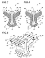
- an adhesion or fastening means 23 in particular in the form of a surface treatment or of elements in relief or recesses, for example protruding fibers, preferably metallic or synthetic fibers, may advantageously be provided for in FIG. outer surface of the coating 18, to improve the connection between the material 4 and the packing material 8 at the interface between these two materials.
- adhesion means 23 has been shown in the perspective view of the figure 5 .
- it is a wire 24 shaped according to a series of successive waves and embedded in the periphery of the coating 18 so that a succession of loops 25 protrude from the latter to facilitate the attachment with the sealing material 4.
- This adhesion means 23 is preferably located mainly at the free end 26 of the extension or lateral extensions 16, which is in the interface zone where the spreading force is the more important in use, especially because of the transversal rolling of vehicles crossing the guide path.
- This adhesion means 23 may however be present anywhere on the outer surface of the coating 18, locally or on the whole of this outer surface.
- This adhesion means 23 can also be realized in the form of a suitable surface treatment or by the use of a cellular or agglomerated material for the packing material 8.
- the filling 2 is filled with sealing material 4 before the coated rail 10 is put in place, by providing in the sealing material 4, for example by sliding formwork during the filling of the engraving, a channel 27 preferably flared to the bottom and substantially complementary shape to the outer shape of the rail 10 provided with its coating 18 ( figure 14 ).
- the channel 27 can also be made after the filling of the engravure 2, by grooving the sealing material 4 present in the engravure 2.
- the coated rail 10 of the invention is force-fitted until it is embedded in this channel 27, for example by means of a steam roller ( figure 15 ).
- This depression is accompanied in the curves of a progressive bending of the rail. This is a true self-bending in which the final bending required is obtained at the end of penetration. Thanks to the characteristics of the rail, the bending is carried out without pouring, that is to say without inclination of the upper part of the rail.
- Depression by force of the rail 10, made possible by the compressible nature of the packing material 8, can be facilitated by a suitable external conformation of the coating 18 and in particular of its lower bulge 19.
- the lower bulge 19 of the coating thus has, for example, beveled edges 28 forming inclined engagement ramps, converging downwards to guide the engagement of the rail 10.
- the rail 10 thus provides a pull-back restraint and if the rollers enclose the rail, the guide system is anchored to the ground.
- the rail 10 according to the invention can be easily dismantled. For this, it is sufficient to cut from above the packing material 8 on either side of the rail 10 in order to extract it from its housing.
- the disassembled rail section can then be replaced by a new coated rail section according to the invention using the same method of laying.
- the rail section must then be locally replaced by an uncoated rail section, the junction and the filling between this section and the remaining portions of packing material 8 anchored in the sealing material conventionally performed by casting resin.
- This method can also be used at the rail welds, where the rail is partially stripped to allow welding, or other mechanical fasteners if necessary.
- sealing material 4 is preferably concrete, instead of the latter, it will be possible to use any other material for immobilizing the coated rail 10 in an engravure 2.
- the invention may be adapted by the skilled person to any type of guide rail or taxi 10 for public transport vehicle without limitation to a particular system for guiding or taxiing.
- a variant of the coated rail 10 according to the invention is engaged with a guide system 30 comprising two inclined rollers 31 V rolling on rolling tracks 14 inclined at the upper part of the head 11 of the guide rail 10 .
- the lugs 32 of each of the inclined guide rollers 31 extend on either side of the head 11 of the rail to below the projecting flanks 33 thereof. They circulate in the lateral grooves 9 formed in the compressible material of the lateral extensions 16 of the coating 18, under the head 11 of the rail and on each side thereof.
- the embodiment of the figure 9 is adapted to a guide roller 34 provided to cooperate with a grooved rail.
- the tread 35 of the roller 34 rolls on the flat upper surface 36 of the guide rail 10 which serves as a raceway.
- This type of roller 34 is provided on one of its sides with a lug 37 forming a peripheral rim.
- This latch 37 moves along a single lateral guide groove 9 formed by means of the coating 18 according to the invention which laterally borders one of the sides of the head 11 of the rail by a lateral extension 16 reproducing the geometry of a conventional throat rail.
- the guide roller 38 of the figure 10 has two lugs 39, forming a peripheral rim on each side of its tread 40.
- the variant of the guide rail 10 shown on the figure 10 is intended to cooperate with this type of roller. It is similar to that of the figure 9 but has a lateral extension 16 of coating on each side of the rail head 11, so as to make a groove 9 bordering laterally the rail head 11 of each side of it, allowing the circulation of the two chins 39.
- the coating 18 may include one or more insert (s) of different material, such as 41 on the Figures 8 to 10 . These inserts may be flush or embedded in the lining material 8 forming the coating 18. They may also be provided projecting outside thereof.
- Such inserts by creating preferred areas of compression, facilitate the installation of the entire assembly of the rail according to the invention.
Landscapes
- Engineering & Computer Science (AREA)
- Mechanical Engineering (AREA)
- Architecture (AREA)
- Civil Engineering (AREA)
- Structural Engineering (AREA)
- Machines For Laying And Maintaining Railways (AREA)
- Railway Tracks (AREA)
- Road Paving Structures (AREA)
- Platform Screen Doors And Railroad Systems (AREA)
- Machine Tool Units (AREA)
- Support Devices For Sliding Doors (AREA)
- Bearings For Parts Moving Linearly (AREA)
Claims (15)
- Realisierungsverfahren eines Roll- oder Führungsträgers, umfassend eine Führungs- oder Rollschiene (10), eine Ummantelung (18), die aus einem Fütterungsmaterial (8) geformt ist, das teilweise die Schiene (10) beschichtet, und eine mit einem Versiegelungsmaterial (4) aufgefüllte Bekiesung (2), wobei diese Führungs- oder Rollschiene (10) einen Kopf (11) in einer Form umfasst, die für das Rollen wenigstens einer Führungs- oder Rollrolle (15) geeignet ist, wobei eine Basis (12) und ein Steg (13) den Kopf (11) und die Basis (12) zusammenführen, wobei das Verfahren dadurch gekennzeichnet ist, dass:• vor der Anbringung der Führungs- oder Rollschiene (10) in der Bekiesung (2) um die Führungs- oder Rollschiene (10) die Ummantelung (18) kontinuierlich über deutlich ihre gesamte Länge, welche wenigstens eine laterale Verlängerung (16) umfasst, die sich hervorstehend zu der Seite erstreckt, in der eine für den Durchgang der Führungs- oder Rollrolle (15) notwendige laterale Auskehlung (9) ausgespart ist, realisiert und eingesetzt wird; und• die mit der Ummantelung (18) beschichtete Führungs- oder Rollschiene (10) in der Bekiesung (2) eingesetzt wird und die mit der Ummantelung (18) beschichtete Führungs- oder Rollschiene (10) direkt durch das Versiegelungsmaterial (4) festgehalten wird, ohne auf eine Zwischenvorrichtung zur Befestigung der Schiene (10) in der Bekiesung (2) zurückzugreifen, die eine Unterbrechung der Ummantelung (18) erfordert.
- Realisierungsverfahren eines Führungs- oder Rollträgers gemäß Anspruch 1, dadurch gekennzeichnet, dass die Stufe des Einsetzens in die Bekiesung (2) und des Festhaltens der mit der Ummantelung (18) beschichteten Führungs- oder Rollschiene (10) die folgenden Stufen umfasst:• Positionierung der mit der Ummantelung (18) beschichteten Führungs- oder Rollschiene (10) an ihrer endgültigen Positionierung in der Bekiesung (2) und Festhalten der Schiene (10) durch eine angepasste vorübergehende Festhaltevorrichtung (22);• Gießen eines Versiegelungsmaterials (4) in die Bekiesung (2) bis zu einem gewünschten Niveau;• Trocknen und Aushärten des Versiegelungsmaterials (4); und• Abnahme der vorübergehenden Festhaltevorrichtung (22).
- Realisierungsverfahren eines Führungs- oder Rollträgers gemäß Anspruch 1, dadurch gekennzeichnet, dass die Stufe des Einsetzens in die Bekiesung (2) und des Festhaltens der mit der Ummantelung (18) beschichteten Führungs- oder Rollschiene (10) die folgenden Stufen umfasst:• Auffüllen der Bekiesung (2) mit einem Versiegelungsmaterial (4), indem in diesem ein Kanal (27) in deutlich komplementärer Form zur der äußeren Form der mit ihrer Ummantelung (18) versehenen Führungs- oder Rollschiene (10) ausgespart wird;• Trocknen und Aushärten des Versiegelungsmaterials (4); und• Einsenkung unter Krafteinwirkung der mit der Ummantelung (18) beschichteten Führungs- oder Rollschiene (10) bis zu ihren Verrasten in dem Kanal (27).
- Verfahren gemäß Anspruch 3, dadurch gekennzeichnet, dass der Kanal (27) per gleitender Verschalung während des Auffüllens der Bekiesung (2) mit dem Versiegelungsmaterial (4) oder per Rillen des Versiegelungsmaterials (4) nach dem Auffüllen der Bekiesung (2) realisiert wird.
- Realisierungsverfahren eines Führungs- oder Rollträgers gemäß Anspruch 1, dadurch gekennzeichnet, dass die Ummantelung (18) um die Führungs- oder Rollschiene (10) verklebt, angehaftet oder vulkanisiert ist.
- Anwendung eines Führungsträgers, der durch das Verfahren gemäß einem der Ansprüche 1 bis 5 erhalten wurde, auf die Führung eines städtischen Straßenfahrzeugs für die öffentliche Beförderung, umfassend ein Führungssystem (30) mit geneigten, V-förmigen Rollen (31).
- Führungs- oder Rollschiene (10), die teilweise mit einer Ummantelung (18) beschichtet ist, die aus einer Fütterung (8) geformt ist und dazu bestimmt ist, in einer Bekiesung (2) eingesetzt zu werden, die mit einem Versiegelungsmaterial (4) aufgefüllt ist, um einen Roll- oder Führungsträger gemäß dem Verfahren des Anspruchs 1 zu realisieren, wobei diese Führungs- oder Rollschiene (10) einen Kopf (11) in zum Rollen von wenigstens einer Führungs- oder Rollschiene (15) angepassten Form, eine Basis (12) und einen Steg (13) formt, der den Kopf (11) und die Basis (12) verbindet, dadurch gekennzeichnet, dass:• wenn die Führungs- oder Rollschiene (10) sich außerhalb der Bekiesung (2) befindet, sie mit der Ummantelung (18) beschichtet ist, die über deutlich ihre gesamte Länge und ohne Unterbrechung für die Anbringung der Zwischenvorrichtung für die Befestigung der Schiene in der Bekiesung (2) kontinuierlich ist; und• dass die Ummantelung (18) wenigstens eine laterale Verlängerung (16) umfasst, die sich hervorstehend zu der Seite erstreckt, in der eine laterale Auskehlung (9) ausgespart ist, die für den Durchgang der Führungs- oder Rollrolle (15) notwendig ist.
- Führungs- oder Rollschiene, die gemäß Anspruch 7 beschichtet ist, dadurch gekennzeichnet, dass die Führungs- oder Rollschiene (10) einen allgemeinen I-förmigen oder deutlich rechteckigen Querschnitt mit einer über seine gesamte Höhe quasi-konstanten Breite aufweist.
- Führungs- oder Rollschiene, die gemäß Anspruch 7 oder 8 beschichtet ist, dadurch gekennzeichnet, dass die Ummantelung (18) zwei laterale Verlängerungen (16) umfasst, die sich auf jeder Seite der Schiene (10) erstrecken.
- Führungs- oder Rollschiene, die gemäß einem der Ansprüche 7 bis 9 beschichtet ist, dadurch gekennzeichnet, dass die Ummantelung (18) deutlich den Konturen der Schiene (10) folgt und eine untere Ausbauchung (19) umfasst, die sich durch einen zentralen Teil (20) nach oben verlängert, der jeweils die Basis (12) und den Steg (13) der Schiene abdeckt, und dass dieser zentrale Teil (20) sich im oberen Teil aufweitet, um wenigstens eine laterale Verlängerung (16) zu formen, die sich hervorstehend zur Seite erstreckt.
- Führungs- oder Rollschiene, die gemäß dem voranstehenden Anspruch beschichtet ist, dadurch gekennzeichnet, dass die untere Ausbauchung (19) der Schiene (10) abgefaste Kanten (28) aufweist, die geneigte Eingriffsrampen formen.
- Führungs- oder Rollschiene, die gemäß einem der Ansprüche 7 bis 11 beschichtet ist, dadurch gekennzeichnet, dass die Ummantelung (18) an ihrer äußeren Oberfläche ein Anhaft- oder Befestigungsmittel (23) umfasst, das die Verbindung mit der Schnittstelle zwischen dem Versiegelungsmaterial (4) und dem Fütterungsmaterial (8) verbessert.
- Führungs- oder Rollschiene, die gemäß dem voranstehenden Anspruch beschichtet ist, dadurch gekennzeichnet, dass das Anhaftmittel (23) aus hervorstehenden metallischen oder synthetischen Fasern oder einem Draht (24) geformt ist, der gemäß einer Serie von aufeinanderfolgenden Wellen angepasst ist.
- Führungs- oder Rollschiene, die gemäß einem der Ansprüche 7 bis 13 beschichtet ist, dadurch gekennzeichnet, dass wenigstens ein Einsatz (41) aus unterschiedlichem Material in der Ummantelung (18) aus Fütterungsmaterial (9) inbegriffen ist.
- Führungs- oder Rollschiene, die gemäß dem voranstehenden Anspruch beschichtet ist, dadurch gekennzeichnet, dass der Einsatz (41) ein länglicher Wulst (42) aus komprimierbarerem Material ist als das Fütterungsmaterial (8), das mit der Ummantelung (18) an der lateralen Verlängerung (16) koextrudiert ist.
Applications Claiming Priority (2)
| Application Number | Priority Date | Filing Date | Title |
|---|---|---|---|
| FR0700050A FR2911154B1 (fr) | 2007-01-05 | 2007-01-05 | Rail de guidage ou de roulage enrobe d'une matiere de garnissage et procede de pose d'un tel rail |
| PCT/FR2007/002161 WO2008096079A2 (fr) | 2007-01-05 | 2007-12-21 | Support de guidage ou de roulage et procede de pose |
Publications (2)
| Publication Number | Publication Date |
|---|---|
| EP2109700A2 EP2109700A2 (de) | 2009-10-21 |
| EP2109700B1 true EP2109700B1 (de) | 2015-07-01 |
Family
ID=38266662
Family Applications (1)
| Application Number | Title | Priority Date | Filing Date |
|---|---|---|---|
| EP07872440.8A Not-in-force EP2109700B1 (de) | 2007-01-05 | 2007-12-21 | Mit einem füllmaterial beschichtete schienenführung oder kugellager und verfahren zur verlegen eines solchen lagers |
Country Status (8)
| Country | Link |
|---|---|
| US (1) | US8167218B2 (de) |
| EP (1) | EP2109700B1 (de) |
| JP (1) | JP5116045B2 (de) |
| KR (1) | KR20090098904A (de) |
| CN (1) | CN101641478B (de) |
| FR (1) | FR2911154B1 (de) |
| RU (1) | RU2456397C2 (de) |
| WO (1) | WO2008096079A2 (de) |
Families Citing this family (10)
| Publication number | Priority date | Publication date | Assignee | Title |
|---|---|---|---|---|
| FR2911154B1 (fr) * | 2007-01-05 | 2014-07-18 | Lohr Ind | Rail de guidage ou de roulage enrobe d'une matiere de garnissage et procede de pose d'un tel rail |
| FR2920448B1 (fr) * | 2007-08-29 | 2013-07-05 | Lohr Ind | Module prefabrique de voie pour vehicule de transport urbain autoguide sur pneumatiques |
| DE102010037520A1 (de) | 2010-09-14 | 2012-03-15 | Demag Cranes & Components Gmbh | Anordnung aus einer Schiene und einem daran befestigten Schleifleitungshalter |
| DE102010037523A1 (de) | 2010-09-14 | 2012-03-15 | Demag Cranes & Components Gmbh | Verbindungsanordnung zweier Schienenabschnitte |
| DE102010037522A1 (de) * | 2010-09-14 | 2012-03-15 | Demag Cranes & Components Gmbh | Schiene für Hängebahnen, Hängekrane u. dgl. |
| DE102010037521A1 (de) | 2010-09-14 | 2012-03-15 | Demag Cranes & Components Gmbh | Vorrichtung zum Aufhängen einer Schiene |
| KR101233931B1 (ko) * | 2010-09-30 | 2013-02-15 | 김충기 | 조립식 지지빔구조체 및 조립식 지지빔구조체의 설치방법 |
| CN103952950B (zh) * | 2014-05-16 | 2016-02-24 | 洛阳双瑞橡塑科技有限公司 | 一种可拆卸结构的埋入式轨道 |
| GB201702558D0 (en) * | 2017-02-16 | 2017-04-05 | Embedded Rail Tech Ltd | Rail installation |
| DE102018109255A1 (de) * | 2018-04-18 | 2019-10-24 | Edilon Sedra Gmbh | Elastisch zu lagernde Schiene |
Family Cites Families (20)
| Publication number | Priority date | Publication date | Assignee | Title |
|---|---|---|---|---|
| FR2270083A1 (en) | 1974-02-04 | 1975-12-05 | Flax V | Thermoplastic container prodn. by extruding tube onto mandrel - and deforming the tube inwardly above the mandrel to form a neck |
| US5181657A (en) * | 1991-05-10 | 1993-01-26 | Omni Rubber Products, Inc. | Composite rubber/concrete railroad grade crossing system |
| US5464152A (en) * | 1994-01-07 | 1995-11-07 | Pacific International Pipe Enterprises, Inc. | Method and apparatus for electrically isolating a rail in a precast concrete grade crossing |
| FR2720083B1 (fr) * | 1994-05-20 | 1996-08-09 | Montcocol Tp | Dispositif à rail de guidage pour véhicule. |
| DE4427237A1 (de) * | 1994-08-02 | 1996-02-08 | Hermann Ortwein | Unterbau für ein Gleis für Schienenfahrzeuge |
| US5538182A (en) * | 1995-04-25 | 1996-07-23 | Omni Products, Inc. | Railroad crossing system |
| US5622312A (en) * | 1995-09-26 | 1997-04-22 | Martin; John K. | Rail track surface structure |
| GB9622924D0 (en) * | 1996-11-04 | 1997-01-08 | Alh Syst Ltd | Polymer embedment of rails |
| FR2757549B1 (fr) * | 1996-12-19 | 1999-01-29 | Lohr Ind | Rail de guidage pour vehicule routier du type autoguide |
| GB9811591D0 (en) * | 1998-05-30 | 1998-07-29 | Penny Charles | Railway or tramway rail and rail fastening system |
| FR2781823B1 (fr) * | 1998-07-29 | 2005-08-26 | Lohr Ind | Rail de guidage a encoches d'engagement-degagement pour un ensemble de guidage a galets notamment inclines |
| ATE267915T1 (de) * | 1998-10-16 | 2004-06-15 | Phoenix Ag | Elektrisch isolierende schienenanordnung |
| DE10138803A1 (de) * | 2001-08-14 | 2003-02-27 | Boegl Max Bauunternehmung Gmbh | Verfahren zum kontinuierlichen Lagern einer Schiene auf einer festen Fahrbahn sowie Justiereinrichtung und feste Fahrbahn |
| FR2835003B1 (fr) * | 2002-01-24 | 2004-02-27 | Alstom | Procede de construction d'une voie ferree sur une dalle de voie en beton |
| WO2003076245A2 (en) * | 2002-03-08 | 2003-09-18 | Iron Horse Engineering Co. | Railway crossing structure |
| FR2861024B1 (fr) * | 2003-10-20 | 2006-03-17 | Lohr Ind | Dispositif de captage d'energie electrique au sol pour l'alimentation d'un vehicule terrestre |
| ITVE20030049A1 (it) * | 2003-11-12 | 2005-05-13 | Claudio Favaron | Dispositivo di bloccaggio di rotaie per veicoli. |
| FR2865986B1 (fr) | 2004-02-09 | 2007-04-13 | Lohr Ind | Galet incline de guidage a utiliser par paire pour un ensemble de guidage le long d'un rail. |
| US7484669B2 (en) * | 2005-04-05 | 2009-02-03 | Metroshield Llc | Insulated rail for electric transit systems and method of making same |
| FR2911154B1 (fr) * | 2007-01-05 | 2014-07-18 | Lohr Ind | Rail de guidage ou de roulage enrobe d'une matiere de garnissage et procede de pose d'un tel rail |
-
2007
- 2007-01-05 FR FR0700050A patent/FR2911154B1/fr not_active Expired - Fee Related
- 2007-12-21 KR KR1020097015626A patent/KR20090098904A/ko not_active Ceased
- 2007-12-21 WO PCT/FR2007/002161 patent/WO2008096079A2/fr not_active Ceased
- 2007-12-21 JP JP2009544422A patent/JP5116045B2/ja not_active Expired - Fee Related
- 2007-12-21 US US12/522,050 patent/US8167218B2/en not_active Expired - Fee Related
- 2007-12-21 EP EP07872440.8A patent/EP2109700B1/de not_active Not-in-force
- 2007-12-21 CN CN2007800491533A patent/CN101641478B/zh not_active Expired - Fee Related
- 2007-12-21 RU RU2009129932/11A patent/RU2456397C2/ru not_active IP Right Cessation
Also Published As
| Publication number | Publication date |
|---|---|
| WO2008096079A2 (fr) | 2008-08-14 |
| JP2010514965A (ja) | 2010-05-06 |
| RU2009129932A (ru) | 2011-02-10 |
| WO2008096079A4 (fr) | 2009-01-22 |
| KR20090098904A (ko) | 2009-09-17 |
| EP2109700A2 (de) | 2009-10-21 |
| FR2911154A1 (fr) | 2008-07-11 |
| FR2911154B1 (fr) | 2014-07-18 |
| RU2456397C2 (ru) | 2012-07-20 |
| CN101641478A (zh) | 2010-02-03 |
| US8167218B2 (en) | 2012-05-01 |
| WO2008096079A3 (fr) | 2008-11-13 |
| JP5116045B2 (ja) | 2013-01-09 |
| CN101641478B (zh) | 2011-11-30 |
| US20100213268A1 (en) | 2010-08-26 |
Similar Documents
| Publication | Publication Date | Title |
|---|---|---|
| WO2008096079A2 (fr) | Support de guidage ou de roulage et procede de pose | |
| EP2191070B1 (de) | Vorgefertigtes modul für eine fahrbahn für ein gummibereiftes, spurgeführtes radfahrzeug | |
| EP2907690B1 (de) | Laufbahnunterlage für ein elektrisches Stromversorgungssystem über den Boden für Landfahrzeug, Schiene, die eine solche Unterlage umfasst, und Verlegeverfahren | |
| EP1331311B1 (de) | Verfahren zum Herstellen eines Gleises auf eine Betonplatte | |
| CA2225508A1 (fr) | Remblai allege | |
| EP0510089B1 (de) | Verfahren zur innenauskleidung einer begehbaren rohrleitung | |
| EP1662050B1 (de) | Bewehrtes Erdbauwerk und Vorderflächenelemente für dessen Bau | |
| FR2922235A1 (fr) | Bande de stabilisation destinee a etre utilisee dans des ouvrages en sol renforce | |
| EP3114281B1 (de) | Lasche mit schutzstreifen | |
| EP3470575B1 (de) | Dichtungsfuge für eisenbahnschiene | |
| FR2840330A1 (fr) | Procede de realisation d'une traverse de chemin de fer, traverse de chemin de fer susceptible d'etre realisee au moyen de ce procede | |
| EP3336249B1 (de) | Herstellungsverfahren eines tragelements einer eisenbahnschiene, durch die umsetzung dieses verfahrens erhaltenes tragelement und eisenbahnschiene, die ein solches element umfasst | |
| BE1014197A3 (fr) | Ensemble d'un rail et d'une jaquette en matiere elastique. | |
| EP1457599A1 (de) | Verfahren zur Herstellung eines schienengleichen Bahnübergangs | |
| FR3025813A1 (fr) | Selle de support de rail de voie ferree | |
| FR3041672B1 (fr) | Coque de piscine en matiere plastique pourvue d'elements de renfort | |
| FR2872829A1 (fr) | Procede de pose de voie ferree encastree, moyens pour sa mise en oeuvre et voie ferree obtenue | |
| EP0444371B1 (de) | Stütz- und Lastverteilungselement für mit flachen Ziegeln bedecktes Dach, und dieses Element enthaltendes Dach | |
| FR2813999A1 (fr) | Procede de pose dans une chaussee d'elements allonges destines a permettre de vehiculer des flux | |
| EP0678133B1 (de) | Verfahren zum herstellen eines bodens mit einem draht als fuehrungsdraht und hilfsmittel zum genauen positionieren von diesem draht unter dem bodenniveau | |
| EP1467023B1 (de) | Eingebettete Schiene | |
| FR3145367A1 (fr) | Infrastructure modulaire pour roulement de vehicule sur pneus | |
| EP1710386A1 (de) | Einbausystem für den Einbau eines Paneelrandes in einen Pfosten | |
| FR2783536A1 (fr) | Ouvrage tubulaire souterrain | |
| FR2783540A1 (fr) | Ouvrage tubulaire |
Legal Events
| Date | Code | Title | Description |
|---|---|---|---|
| PUAI | Public reference made under article 153(3) epc to a published international application that has entered the european phase |
Free format text: ORIGINAL CODE: 0009012 |
|
| 17P | Request for examination filed |
Effective date: 20090723 |
|
| AK | Designated contracting states |
Kind code of ref document: A2 Designated state(s): AT BE BG CH CY CZ DE DK EE ES FI FR GB GR HU IE IS IT LI LT LU LV MC MT NL PL PT RO SE SI SK TR |
|
| DAX | Request for extension of the european patent (deleted) | ||
| 17Q | First examination report despatched |
Effective date: 20120801 |
|
| GRAP | Despatch of communication of intention to grant a patent |
Free format text: ORIGINAL CODE: EPIDOSNIGR1 |
|
| INTG | Intention to grant announced |
Effective date: 20150216 |
|
| RAP1 | Party data changed (applicant data changed or rights of an application transferred) |
Owner name: NEWTL |
|
| GRAS | Grant fee paid |
Free format text: ORIGINAL CODE: EPIDOSNIGR3 |
|
| GRAA | (expected) grant |
Free format text: ORIGINAL CODE: 0009210 |
|
| AK | Designated contracting states |
Kind code of ref document: B1 Designated state(s): AT BE BG CH CY CZ DE DK EE ES FI FR GB GR HU IE IS IT LI LT LU LV MC MT NL PL PT RO SE SI SK TR |
|
| REG | Reference to a national code |
Ref country code: GB Ref legal event code: FG4D Free format text: NOT ENGLISH |
|
| REG | Reference to a national code |
Ref country code: AT Ref legal event code: REF Ref document number: 734043 Country of ref document: AT Kind code of ref document: T Effective date: 20150715 Ref country code: CH Ref legal event code: EP |
|
| REG | Reference to a national code |
Ref country code: IE Ref legal event code: FG4D Free format text: LANGUAGE OF EP DOCUMENT: FRENCH |
|
| REG | Reference to a national code |
Ref country code: DE Ref legal event code: R096 Ref document number: 602007041989 Country of ref document: DE |
|
| REG | Reference to a national code |
Ref country code: AT Ref legal event code: MK05 Ref document number: 734043 Country of ref document: AT Kind code of ref document: T Effective date: 20150701 |
|
| REG | Reference to a national code |
Ref country code: NL Ref legal event code: MP Effective date: 20150701 |
|
| REG | Reference to a national code |
Ref country code: FR Ref legal event code: PLFP Year of fee payment: 9 |
|
| REG | Reference to a national code |
Ref country code: LT Ref legal event code: MG4D |
|
| PG25 | Lapsed in a contracting state [announced via postgrant information from national office to epo] |
Ref country code: LV Free format text: LAPSE BECAUSE OF FAILURE TO SUBMIT A TRANSLATION OF THE DESCRIPTION OR TO PAY THE FEE WITHIN THE PRESCRIBED TIME-LIMIT Effective date: 20150701 Ref country code: LT Free format text: LAPSE BECAUSE OF FAILURE TO SUBMIT A TRANSLATION OF THE DESCRIPTION OR TO PAY THE FEE WITHIN THE PRESCRIBED TIME-LIMIT Effective date: 20150701 Ref country code: GR Free format text: LAPSE BECAUSE OF FAILURE TO SUBMIT A TRANSLATION OF THE DESCRIPTION OR TO PAY THE FEE WITHIN THE PRESCRIBED TIME-LIMIT Effective date: 20151002 Ref country code: FI Free format text: LAPSE BECAUSE OF FAILURE TO SUBMIT A TRANSLATION OF THE DESCRIPTION OR TO PAY THE FEE WITHIN THE PRESCRIBED TIME-LIMIT Effective date: 20150701 |
|
| PG25 | Lapsed in a contracting state [announced via postgrant information from national office to epo] |
Ref country code: ES Free format text: LAPSE BECAUSE OF FAILURE TO SUBMIT A TRANSLATION OF THE DESCRIPTION OR TO PAY THE FEE WITHIN THE PRESCRIBED TIME-LIMIT Effective date: 20150701 Ref country code: PL Free format text: LAPSE BECAUSE OF FAILURE TO SUBMIT A TRANSLATION OF THE DESCRIPTION OR TO PAY THE FEE WITHIN THE PRESCRIBED TIME-LIMIT Effective date: 20150701 Ref country code: AT Free format text: LAPSE BECAUSE OF FAILURE TO SUBMIT A TRANSLATION OF THE DESCRIPTION OR TO PAY THE FEE WITHIN THE PRESCRIBED TIME-LIMIT Effective date: 20150701 Ref country code: IS Free format text: LAPSE BECAUSE OF FAILURE TO SUBMIT A TRANSLATION OF THE DESCRIPTION OR TO PAY THE FEE WITHIN THE PRESCRIBED TIME-LIMIT Effective date: 20151101 Ref country code: SE Free format text: LAPSE BECAUSE OF FAILURE TO SUBMIT A TRANSLATION OF THE DESCRIPTION OR TO PAY THE FEE WITHIN THE PRESCRIBED TIME-LIMIT Effective date: 20150701 Ref country code: PT Free format text: LAPSE BECAUSE OF FAILURE TO SUBMIT A TRANSLATION OF THE DESCRIPTION OR TO PAY THE FEE WITHIN THE PRESCRIBED TIME-LIMIT Effective date: 20151102 |
|
| REG | Reference to a national code |
Ref country code: DE Ref legal event code: R097 Ref document number: 602007041989 Country of ref document: DE |
|
| PG25 | Lapsed in a contracting state [announced via postgrant information from national office to epo] |
Ref country code: CZ Free format text: LAPSE BECAUSE OF FAILURE TO SUBMIT A TRANSLATION OF THE DESCRIPTION OR TO PAY THE FEE WITHIN THE PRESCRIBED TIME-LIMIT Effective date: 20150701 Ref country code: DK Free format text: LAPSE BECAUSE OF FAILURE TO SUBMIT A TRANSLATION OF THE DESCRIPTION OR TO PAY THE FEE WITHIN THE PRESCRIBED TIME-LIMIT Effective date: 20150701 Ref country code: EE Free format text: LAPSE BECAUSE OF FAILURE TO SUBMIT A TRANSLATION OF THE DESCRIPTION OR TO PAY THE FEE WITHIN THE PRESCRIBED TIME-LIMIT Effective date: 20150701 Ref country code: SK Free format text: LAPSE BECAUSE OF FAILURE TO SUBMIT A TRANSLATION OF THE DESCRIPTION OR TO PAY THE FEE WITHIN THE PRESCRIBED TIME-LIMIT Effective date: 20150701 |
|
| PLBE | No opposition filed within time limit |
Free format text: ORIGINAL CODE: 0009261 |
|
| STAA | Information on the status of an ep patent application or granted ep patent |
Free format text: STATUS: NO OPPOSITION FILED WITHIN TIME LIMIT |
|
| PG25 | Lapsed in a contracting state [announced via postgrant information from national office to epo] |
Ref country code: BE Free format text: LAPSE BECAUSE OF NON-PAYMENT OF DUE FEES Effective date: 20151231 Ref country code: RO Free format text: LAPSE BECAUSE OF FAILURE TO SUBMIT A TRANSLATION OF THE DESCRIPTION OR TO PAY THE FEE WITHIN THE PRESCRIBED TIME-LIMIT Effective date: 20150701 |
|
| 26N | No opposition filed |
Effective date: 20160404 |
|
| REG | Reference to a national code |
Ref country code: DE Ref legal event code: R119 Ref document number: 602007041989 Country of ref document: DE |
|
| PG25 | Lapsed in a contracting state [announced via postgrant information from national office to epo] |
Ref country code: MC Free format text: LAPSE BECAUSE OF FAILURE TO SUBMIT A TRANSLATION OF THE DESCRIPTION OR TO PAY THE FEE WITHIN THE PRESCRIBED TIME-LIMIT Effective date: 20150701 Ref country code: LU Free format text: LAPSE BECAUSE OF FAILURE TO SUBMIT A TRANSLATION OF THE DESCRIPTION OR TO PAY THE FEE WITHIN THE PRESCRIBED TIME-LIMIT Effective date: 20151221 |
|
| REG | Reference to a national code |
Ref country code: CH Ref legal event code: PL |
|
| GBPC | Gb: european patent ceased through non-payment of renewal fee |
Effective date: 20151221 |
|
| PG25 | Lapsed in a contracting state [announced via postgrant information from national office to epo] |
Ref country code: SI Free format text: LAPSE BECAUSE OF FAILURE TO SUBMIT A TRANSLATION OF THE DESCRIPTION OR TO PAY THE FEE WITHIN THE PRESCRIBED TIME-LIMIT Effective date: 20150701 |
|
| REG | Reference to a national code |
Ref country code: IE Ref legal event code: MM4A |
|
| PG25 | Lapsed in a contracting state [announced via postgrant information from national office to epo] |
Ref country code: GB Free format text: LAPSE BECAUSE OF NON-PAYMENT OF DUE FEES Effective date: 20151221 Ref country code: LI Free format text: LAPSE BECAUSE OF NON-PAYMENT OF DUE FEES Effective date: 20151231 Ref country code: DE Free format text: LAPSE BECAUSE OF NON-PAYMENT OF DUE FEES Effective date: 20160701 Ref country code: IE Free format text: LAPSE BECAUSE OF NON-PAYMENT OF DUE FEES Effective date: 20151221 Ref country code: CH Free format text: LAPSE BECAUSE OF NON-PAYMENT OF DUE FEES Effective date: 20151231 |
|
| REG | Reference to a national code |
Ref country code: FR Ref legal event code: PLFP Year of fee payment: 10 |
|
| PG25 | Lapsed in a contracting state [announced via postgrant information from national office to epo] |
Ref country code: IT Free format text: LAPSE BECAUSE OF NON-PAYMENT OF DUE FEES Effective date: 20151221 |
|
| PG25 | Lapsed in a contracting state [announced via postgrant information from national office to epo] |
Ref country code: HU Free format text: LAPSE BECAUSE OF FAILURE TO SUBMIT A TRANSLATION OF THE DESCRIPTION OR TO PAY THE FEE WITHIN THE PRESCRIBED TIME-LIMIT; INVALID AB INITIO Effective date: 20071221 Ref country code: BG Free format text: LAPSE BECAUSE OF FAILURE TO SUBMIT A TRANSLATION OF THE DESCRIPTION OR TO PAY THE FEE WITHIN THE PRESCRIBED TIME-LIMIT Effective date: 20150701 |
|
| PG25 | Lapsed in a contracting state [announced via postgrant information from national office to epo] |
Ref country code: NL Free format text: LAPSE BECAUSE OF FAILURE TO SUBMIT A TRANSLATION OF THE DESCRIPTION OR TO PAY THE FEE WITHIN THE PRESCRIBED TIME-LIMIT Effective date: 20150701 Ref country code: CY Free format text: LAPSE BECAUSE OF FAILURE TO SUBMIT A TRANSLATION OF THE DESCRIPTION OR TO PAY THE FEE WITHIN THE PRESCRIBED TIME-LIMIT Effective date: 20150701 |
|
| PG25 | Lapsed in a contracting state [announced via postgrant information from national office to epo] |
Ref country code: MT Free format text: LAPSE BECAUSE OF FAILURE TO SUBMIT A TRANSLATION OF THE DESCRIPTION OR TO PAY THE FEE WITHIN THE PRESCRIBED TIME-LIMIT Effective date: 20150701 Ref country code: TR Free format text: LAPSE BECAUSE OF FAILURE TO SUBMIT A TRANSLATION OF THE DESCRIPTION OR TO PAY THE FEE WITHIN THE PRESCRIBED TIME-LIMIT Effective date: 20150701 |
|
| REG | Reference to a national code |
Ref country code: FR Ref legal event code: CA Effective date: 20170829 |
|
| REG | Reference to a national code |
Ref country code: FR Ref legal event code: PLFP Year of fee payment: 11 |
|
| PGFP | Annual fee paid to national office [announced via postgrant information from national office to epo] |
Ref country code: FR Payment date: 20171006 Year of fee payment: 11 |
|
| PG25 | Lapsed in a contracting state [announced via postgrant information from national office to epo] |
Ref country code: FR Free format text: LAPSE BECAUSE OF NON-PAYMENT OF DUE FEES Effective date: 20181231 |