EP2109702B1 - Feuerhydrant mit Anschlüssvorrichtung - Google Patents
Feuerhydrant mit Anschlüssvorrichtung Download PDFInfo
- Publication number
- EP2109702B1 EP2109702B1 EP20080761916 EP08761916A EP2109702B1 EP 2109702 B1 EP2109702 B1 EP 2109702B1 EP 20080761916 EP20080761916 EP 20080761916 EP 08761916 A EP08761916 A EP 08761916A EP 2109702 B1 EP2109702 B1 EP 2109702B1
- Authority
- EP
- European Patent Office
- Prior art keywords
- plug
- fire hydrant
- control tube
- retention means
- socket
- Prior art date
- Legal status (The legal status is an assumption and is not a legal conclusion. Google has not performed a legal analysis and makes no representation as to the accuracy of the status listed.)
- Not-in-force
Links
- XLYOFNOQVPJJNP-UHFFFAOYSA-N water Substances O XLYOFNOQVPJJNP-UHFFFAOYSA-N 0.000 claims abstract description 18
- 230000009471 action Effects 0.000 claims description 9
- 238000000605 extraction Methods 0.000 claims description 7
- 210000002445 nipple Anatomy 0.000 claims description 7
- 230000014759 maintenance of location Effects 0.000 claims 10
- 238000007789 sealing Methods 0.000 abstract description 2
- 230000008033 biological extinction Effects 0.000 abstract 1
- 230000006870 function Effects 0.000 description 3
- 230000016571 aggressive behavior Effects 0.000 description 2
- 238000003780 insertion Methods 0.000 description 2
- 230000037431 insertion Effects 0.000 description 2
- 238000009434 installation Methods 0.000 description 2
- 238000002955 isolation Methods 0.000 description 2
- 238000004026 adhesive bonding Methods 0.000 description 1
- 230000000903 blocking effect Effects 0.000 description 1
- 230000006378 damage Effects 0.000 description 1
- 230000006866 deterioration Effects 0.000 description 1
- 238000005553 drilling Methods 0.000 description 1
- 238000002513 implantation Methods 0.000 description 1
- 230000007246 mechanism Effects 0.000 description 1
- 230000004048 modification Effects 0.000 description 1
- 238000012986 modification Methods 0.000 description 1
- 230000035515 penetration Effects 0.000 description 1
- 230000000452 restraining effect Effects 0.000 description 1
- 238000010079 rubber tapping Methods 0.000 description 1
- 238000005070 sampling Methods 0.000 description 1
- 238000011144 upstream manufacturing Methods 0.000 description 1
Images


Classifications
-
- E—FIXED CONSTRUCTIONS
- E03—WATER SUPPLY; SEWERAGE
- E03B—INSTALLATIONS OR METHODS FOR OBTAINING, COLLECTING, OR DISTRIBUTING WATER
- E03B9/00—Methods or installations for drawing-off water
- E03B9/02—Hydrants; Arrangements of valves therein; Keys for hydrants
- E03B9/04—Column hydrants
-
- E—FIXED CONSTRUCTIONS
- E03—WATER SUPPLY; SEWERAGE
- E03B—INSTALLATIONS OR METHODS FOR OBTAINING, COLLECTING, OR DISTRIBUTING WATER
- E03B9/00—Methods or installations for drawing-off water
- E03B9/02—Hydrants; Arrangements of valves therein; Keys for hydrants
- E03B9/08—Underground hydrants
-
- Y—GENERAL TAGGING OF NEW TECHNOLOGICAL DEVELOPMENTS; GENERAL TAGGING OF CROSS-SECTIONAL TECHNOLOGIES SPANNING OVER SEVERAL SECTIONS OF THE IPC; TECHNICAL SUBJECTS COVERED BY FORMER USPC CROSS-REFERENCE ART COLLECTIONS [XRACs] AND DIGESTS
- Y10—TECHNICAL SUBJECTS COVERED BY FORMER USPC
- Y10T—TECHNICAL SUBJECTS COVERED BY FORMER US CLASSIFICATION
- Y10T137/00—Fluid handling
- Y10T137/5327—Hydrant type
- Y10T137/5456—With casing
- Y10T137/5468—Cap, cover or hood
-
- Y—GENERAL TAGGING OF NEW TECHNOLOGICAL DEVELOPMENTS; GENERAL TAGGING OF CROSS-SECTIONAL TECHNOLOGIES SPANNING OVER SEVERAL SECTIONS OF THE IPC; TECHNICAL SUBJECTS COVERED BY FORMER USPC CROSS-REFERENCE ART COLLECTIONS [XRACs] AND DIGESTS
- Y10—TECHNICAL SUBJECTS COVERED BY FORMER USPC
- Y10T—TECHNICAL SUBJECTS COVERED BY FORMER US CLASSIFICATION
- Y10T137/00—Fluid handling
- Y10T137/5327—Hydrant type
- Y10T137/5485—With valve at outlet
Definitions
- the field of the present invention is that of fire-fighting means and in particular water supply terminals, such as poles and hydrants, united under the generic term of hydrants.
- a fire hydrant is, as its name suggests, a hollow pole in which is arranged a set of controls, and which allows the delivery of water, under pressure, from the main supply network, to fire-fighting officers.
- the pole is equipped with plugs on which firemen come to connect their pipes, which are closed by plugs outside their period of use.
- the controls allow, thanks to a flywheel, fixed or removable, or to a key fitting on an operating end, to move the valve of a valve, called valve, which is placed downstream of the delivery pipe of the water and whose opening causes the provision of water.
- the post is very often locked in a hood with a door lock to try to avoid inadvertent sampling of water.
- a fire hydrant differs somewhat from a pole in that it is completely embedded in the ground so as to be less visible, but it remains almost identical in its operation, namely that it has a plug for the connection of the fire brigade hoses and a maneuvering nozzle, to which a key is fitted, to actuate the valve and allow water from the main network to flow.
- Each pole like each mouth, is always preceded upstream, just before connecting to the pipe from the water supply network, a "keyed".
- This one thus designated by abuse of language, is in fact an isolation valve which makes it possible to isolate the hydrant of the main network.
- the object of the present invention is to remedy these drawbacks by proposing a locking device positioned inside the post or the mouth so as to prevent access to the water, even in case of deterioration, whether intentional or accidental, of the cap.
- the device interacts for this with the control tube of the valve so as to prevent the extraction of the plug either towards the outside or towards the inside of the hydrant.
- the subject of the invention is a fire hydrant comprising a securing device according to claim 1.
- At least one second retaining means deploys during its locking inside said duct.
- said at least one first retaining means is adapted to deviate from the axis of the plug to position laterally with respect to the control tube and adapted to approach said tube under the action a locking device so as to, in the locking position, radially block said plug with respect to said control tube.
- control tube carries at least one piece with which said at least one first retaining means cooperates.
- This second embodiment allows, in addition to the prohibition of the depression of the plug, to prevent the rotation of the control tube by blocking a part which is attached thereto laterally.
- said insert on said control tube forms at least one stud protruding from said tube and wherein at least one first retaining means bears on said at least one stud.
- This configuration is used for upgrading existing fire posts, after drilling the control tube from the stake in question and insertion of a bar calibrated in length or implantation of a nipple-shaped buffer.
- At least a first retaining means is able to deviate from the axis of the plug to position laterally with respect to the control tube and is adapted to approach said tube under the action of a locking device so as to, in locked position, block in rotation in both directions said at least one insert.
- said at least one first retaining means is a ring-shaped pallet in which at least one stud carried by said insert engages.
- said at least one first retaining means is a pallet having the form of a hollow cone in which engages at least one stud carried by said insert.
- said stopper has the shape of a hollow cylinder in its upper part so as to form two lateral appendages separated from each other by a recessed portion whose bottom constitutes the first restraining means.
- This shape makes it possible to grip the control tube so as to ensure the centering of the plug and, incidentally, to prevent its rotation about the axis of symmetry of the cylinder.
- said plug is able to fit completely into the socket so as not to interfere with the placement of a cover on the hooking device of the cylindrical portion of said plug.
- This configuration facilitates the installation of the invention for upgrading existing fire posts.
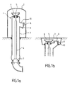
- a fire pole comprising a body 1 enclosed for its upper part in a cowling 2.
- This body is formed essentially of a pipe 3 substantially vertical, a first portion, in the case of the fire hydrant is buried in the ground and a second part above ground.
- This duct carries in it a control tube 4, the upper end of which has the shape of a maneuvering endpiece 5 on which a fixed or removable control handle 6 is engaged.
- the control tube carries a valve 7 making valve for the release of water from the main supply network.
- the pipe 3 is fixed at its lower part on the water supply pipe coming from the main network and forms, at the level of the valve 7, a seat for the seal of the latter.
- At the top of the pipe 3 leads to one or more outlets 8 (usually three for a fire hydrant, one for a mouth) on which are connected the fire hose.
- the outlets have a cylindrical portion 10 deviating, in the case of a fire hydrant, substantially radially from the pipe 3 and terminate in an attachment device for a cap 9 which seals when the taken is not used.
- a plug 9 for fire hydrant according to a first embodiment of the invention comprising a cover 11 adapted to be fixed on the hooking device of the cylindrical portion 10 of the socket 8.
- This plug is a carrier of a set of elements intended to penetrate inside the socket 8 so as to prohibit its tearing or penetration.
- a locking device 12 such as a lock actuated by a key (not shown) which controls bolts 13 may in the first place to deviate from the axis of the plug to prevent the removal of the plug and secondly to retract inside said cap to release of the catch.
- These bolts are here positioned so that they deploy in the locked position inside the pipe 3.
- the cap 9 also carries beyond these bolts a support 14 extending towards the control tube 4 On this support is fixed a pallet 15 which substantially abuts on the control tube 4 when the cap is locked on the socket 8.
- the figure 3 shows the same elements when the cap is unlocked and is being removed from the socket 8.
- the support 14 is made in two parts 14a and 14b. These two parts 14a and 14b carry two pallets 15a and 15b which can deviate from the axis of the plug once they have penetrated inside the pipe 3; they can then, once the plug 9 has been put in place, be brought back towards one another, under the action for example of the key of the locking device 12, so as to grip the control tube 4
- the shape of these two vanes 15a and 15b is such that they can, once closed, trap the control tube between them and even, if the support is strong enough, prevent the rotation thereof.
- the bolts 13 are useless (or maintained as redundancy) since the vanes 15a and 15b prevent, by themselves, both the extraction of the plug and its expulsion inside the pipe 3.
- the stopper also has a lock, equipped if necessary with bolts 13 (not shown on the figure 4 ) as in the first embodiment, for the purpose of preventing the extraction of the plug.
- the control tube 4 is pierced radially by a bar 16, two pins 16a and 16b protrude inside the pipe 3.
- the support 14 is made in two parts 14a and 14b ending in pallets 15a and 15b likely to bear on the nipples 16a and 16b so as to prevent rotation of the control tube 4 when the plug is in place.
- the parts 14a and 14b can deviate from the axis of the plug once they have penetrated inside the pipe 3 ; they can then, once the cap 9 has been put in place, be brought back to one another, under the action of the key of the lock 12, for example to imprison the two pins 16a and 16b .
- the pallets 15a and 15b have a shape adapted to the imprisonment of the nipples, such as that of a hollow ring or cone.
- the bolts 13 are useless (or maintained as redundancy), their function of preventing the extraction of the plug being already provided by the pallets 15a and 15b.
- the plug 9 has a cylindrical shape whose upper part is recessed to form two lateral appendices 17 separated from each other by a recessed portion whose bottom constitutes the pallet 15 intended to rest on the control tube 4 and to prevent the plug from sinking into the socket.
- the two appendices 17 have the function of clamping the control tube 4 so as to ensure the centering of the plug and, secondarily, to prevent its rotation about the axis of symmetry of the cylinder.
- the bolt 13 On the cylindrical portion of the plug which is disposed on the side of the end opposite the appendages 17 is the bolt 13 which is actuated by a lock 12 accessible from the underside of the plug that is to say the face opposite the hollow part. On this same face also includes a device 18 for extracting the plug from the socket.
- the bolt 13 is positioned on the cylinder at a distance from the lower face such that after insertion of the plug into the socket 8 and bearing on the control tube 4 of the bottom 15 of the recessed portion, it is located inside the pipe 3 and that it can be operated to bear on the inner face of the pipe and thus block the extraction of the plug. the catch.
- control tube 4 carries a stud 16c having the form of a buffer extending substantially vertically along the control tube and positioned vis-à-vis the plug 9. It is fixed on the control tube by a fastening means such as a screw engaging in a tapped hole in the tube and is positioned on the tube at a height such that when the plug 9 is put in place, its lower part comes stand just above the 16c nipple.
- a fastening means such as a screw engaging in a tapped hole in the tube and is positioned on the tube at a height such that when the plug 9 is put in place, its lower part comes stand just above the 16c nipple.
- the control tube is blocked in its ascent by the pin 16c which abuts on the body of the cylindrical plug 9 at the edge 20 of the junction of the recessed portion with the cylindrical portion.
- the cap does not carry a lid as in the previous configurations. But as it integrates entirely inside the water intake 8, it is possible to reuse the lid 11 current hydrants to ensure the protection of the plug against external aggression.
- the introduction of a plug is done in a completely conventional manner with the introduction of the pallet 15, the support 14 and the lock 12 inside the cylindrical portion 10 of the plug 8. Once that the lid 11 of the cap comes against the cylindrical portion 10, it is fixed in a known manner such as for example by a rotation which creates the necessary support on the cylindrical portion to ensure the sealing of the cap.
- the lock 12 is then actuated by the key which deploys the bolts 13 inside the pipe 3 and thus prevents the removal of the plug from the socket.
- the bolt 13 does not exist (or exists to provide redundancy) and the two parts of the support 14 are movable laterally.
- the two parts 14a and 14b are first tightened to enter the cylindrical portion 10 of the socket 8.
- these pallets differ, for example under the action of a spring or by a particular action on the key, so as to leave the control tube 4 and, in the second embodiment, the pins 16a and 16b, pass between them.
- the locking action by the key of the lock 12 triggers the bringing together of the parts 14a and 14b and, as a result, the imprisonment by the vanes 15a and 15b, of the control tube 4 in the first mode and the pins 16a and 16b in the second mode.
Landscapes
- Health & Medical Sciences (AREA)
- Life Sciences & Earth Sciences (AREA)
- Engineering & Computer Science (AREA)
- Hydrology & Water Resources (AREA)
- Public Health (AREA)
- Water Supply & Treatment (AREA)
- Fire-Extinguishing By Fire Departments, And Fire-Extinguishing Equipment And Control Thereof (AREA)
- Quick-Acting Or Multi-Walled Pipe Joints (AREA)
- Valve Housings (AREA)
- Installation Of Indoor Wiring (AREA)
- Mutual Connection Of Rods And Tubes (AREA)
- Rigid Pipes And Flexible Pipes (AREA)
Claims (10)
- Feuerhydrant, der eine Kanalisation (3) umfasst, ein Steuerrohr (4), das an einem Ende mit einem Manövrierstück (5) und an dem anderen Ende mit einem Ventil (7) ausgestattet ist, das imstande ist, die Versorgung der Kanalisation (3) mit Wasser vom Hauptnetz aus zu erlauben, mindestens eine Zapfstelle (8), die an der Kanalisation angeschlossen ist und imstande, Feuerlöschrohre aufzunehmen, und eine Sicherheitsvorrichtung, die einen Verschluss (9) umfasst, wobei die Zapfstelle (8) den Dichtverschluss (9) aufweist, wobei der Verschluss (9) mindestens ein erstes Rückhaltemittel (15, 15a, 15b) trägt, das imstande ist, mit dem Steuerrohr (4) oder mit einer Wand der Kanalisation (3) derart zusammenzuarbeiten, dass das Einbringen des Verschlusses in die Zapfstelle untersagt wird, dadurch gekennzeichnet, dass der Verschluss (9) weiterhin mindestens ein zweites, von einer Verriegelungsvorrichtung (12) betätigtes Rückhaltemittel (13) trägt, dass dazu bestimmt ist, das Herausziehen des Verschlusses aus der Zapfstelle zu verhindern.
- Feuerhydrant nach Anspruch 1, wobei sich das mindestens eine zweite Rückhaltemittel (13) bei seiner Verriegelung in der Kanalisation (3) entfaltet.
- Feuerhydrant nach einem der vorangehenden Ansprüche, wobei das mindestens eine erste Rückhaltemittel (15a, 15b) imstande ist, sich von der Achse des Verschlusses (9) abzuspreizen, um sich seitlich im Verhältnis zum Steuerrohr (4) zu positionieren, und imstande ist, sich unter der Einwirkung einer Verriegelungsvorrichtung (12) derart an das Rohr anzunähern, dass in Verriegelungsposition der Verschluss im Verhältnis zum Steuerrohr radial blockiert wird.
- Feuerhydrant nach Anspruch 1, wobei das Steuerrohr (4) mindestens ein Teil (16, 16a, 16b, 16c) trägt, mit dem das mindestens eine erste Rückhaltemittel (15, 15a, 15b) zusammenarbeitet.
- Feuerhydrant nach Anspruch 4, wobei das auf dem Steuerrohr angebrachte Teil (16) mindestens einen Zapfen (16, 16a, 16b, 16c) bildet, der über das Rohr hinausragt und wobei sich das mindestens eine erste Rückhaltemittel (15a, 15b) auf dem mindestens einen Zapfen abstützt.
- Feuerhydrant nach einem der Ansprüche 4 oder 5, wobei das mindestens eine erste Rückhaltemittel (15a, 15b) imstande ist, sich von der Achse des Verschlusses (9) abzuspreizen, um sich seitlich im Verhältnis zum Steuerrohr (4) zu positionieren, und imstande ist, sich unter der Einwirkung einer Verriegelungsvorrichtung (12) derart an das Rohr anzunähern, dass in Verriegelungsposition das mindestens eine aufgesetzte Teil (16a, 16b, 16c) in die zwei Richtungen in Rotation blockiert wird.
- Feuerhydrant nach Anspruch 6, wobei das mindestens eine erste Rückhaltemittel (15a, 16b) ein ringförmiges Plättchen ist, in das mindestens ein von dem aufgesetzten Teil (16) getragener Zapfen (16a, 16b) eingreift.
- Feuerhydrant nach Anspruch 6, wobei das mindestens eine erste Rückhaltemittel ein Plättchen (15a, 16b) ist, das die Form eines ausgehöhlten Konus hat, in den mindestens ein von dem aufgesetzten Teil (16) getragener Zapfen (16a, 16b) eingreift.
- Feuerhydrant nach einem der Ansprüche 4 oder 5, wobei der Verschluss (9) die Form eines Zylinders hat, der in seinem oberen Abschnitt derart ausgehöhlt ist, dass er zwei seitliche Fortsätze (17) bildet, die voneinander durch einen hohlen Abschnitt getrennt sind, dessen Boden das erste Rückhaltemittel (15) darstellt.
- Feuerhydrant nach Anspruch 9, wobei der Verschluss (9) imstande ist, sich voll und ganz in die Zapfstelle (8) einzufügen, ohne mit der Platzierung eines Deckels (11) auf der Koppelvorrichtung des zylindrischen Abschnitts (10) der Zapfstelle (8) in Konflikt zu kommen.
Applications Claiming Priority (2)
| Application Number | Priority Date | Filing Date | Title |
|---|---|---|---|
| FR0752898A FR2911889B1 (fr) | 2007-01-26 | 2007-01-26 | Dispositif de securisation des prises des poteaux d'incendie a l'aide du tube de commande |
| PCT/FR2008/050042 WO2008099103A2 (fr) | 2007-01-26 | 2008-01-09 | Dispositif de securisation des prises des poteaux d'incendie a l'aide du tube de commande |
Publications (2)
| Publication Number | Publication Date |
|---|---|
| EP2109702A2 EP2109702A2 (de) | 2009-10-21 |
| EP2109702B1 true EP2109702B1 (de) | 2011-03-02 |
Family
ID=38421145
Family Applications (1)
| Application Number | Title | Priority Date | Filing Date |
|---|---|---|---|
| EP20080761916 Not-in-force EP2109702B1 (de) | 2007-01-26 | 2008-01-09 | Feuerhydrant mit Anschlüssvorrichtung |
Country Status (8)
| Country | Link |
|---|---|
| US (1) | US8276608B2 (de) |
| EP (1) | EP2109702B1 (de) |
| AT (1) | ATE500389T1 (de) |
| AU (1) | AU2008214493B2 (de) |
| CA (1) | CA2676272C (de) |
| DE (1) | DE602008005265D1 (de) |
| FR (1) | FR2911889B1 (de) |
| WO (1) | WO2008099103A2 (de) |
Families Citing this family (6)
| Publication number | Priority date | Publication date | Assignee | Title |
|---|---|---|---|---|
| WO2010051458A1 (en) | 2008-10-31 | 2010-05-06 | Calera Corporation | Non-cementitious compositions comprising co2 sequestering additives |
| FR2995920B1 (fr) * | 2012-09-26 | 2014-09-05 | Camene | Dispositif de manœuvre ultime pour hydrant securise |
| FR3026419A1 (fr) | 2014-09-30 | 2016-04-01 | Camene | Systeme d'outillage, de preference pour hydrant, par exemple pour les interventions des sapeurs pompier, et ensemble correspondant |
| PL233189B1 (pl) * | 2017-09-19 | 2019-09-30 | Armatura Woda Kanalizacja Spolka Z Ograniczona Odpowiedzialnoscia | Obudowa do zasuw ze zintegrowanym wskaźnikiem otwarcia |
| CN115162468B (zh) * | 2022-04-14 | 2025-02-07 | 烟台淼盾物联技术有限公司 | 一种多功能的防盗水消火栓 |
| CN118079293B (zh) * | 2024-04-24 | 2024-06-21 | 百安消防科技有限公司 | 一种防盗消火栓及其使用方法 |
Family Cites Families (10)
| Publication number | Priority date | Publication date | Assignee | Title |
|---|---|---|---|---|
| US2083319A (en) * | 1936-10-17 | 1937-06-08 | August H Daviet | Fire hydrant |
| US2627277A (en) * | 1950-04-28 | 1953-02-03 | George H Martin | Multiple valve control outlet hydrant |
| US3914966A (en) * | 1973-03-05 | 1975-10-28 | Louis Bello | Protection device and tool for fire hydrant |
| US3939861A (en) * | 1974-07-19 | 1976-02-24 | Thompson William J | Fire hydrant |
| US4280525A (en) * | 1979-04-18 | 1981-07-28 | Center Compression Lock Company, Inc. | Tamperproof cap assembly for hydrant |
| FR2740849B1 (fr) * | 1995-11-08 | 1997-12-19 | Bayard | Dispositif d'ouverture-fermeture de robinet, notamment de robinet de borne d'incendie |
| US6058957A (en) * | 1997-09-08 | 2000-05-09 | Honigsbaum; Richard | Water saver fire hydrant |
| US6112761A (en) * | 1999-11-15 | 2000-09-05 | Scotto; Gary | Fire hydrant locking device and wrench |
| WO2003049810A2 (en) * | 2001-12-05 | 2003-06-19 | Huggler Frederick J | Fire hydrant lock |
| US6901950B1 (en) * | 2004-06-08 | 2005-06-07 | James E. Burt | Fire hydrant locking device |
-
2007
- 2007-01-26 FR FR0752898A patent/FR2911889B1/fr not_active Expired - Fee Related
-
2008
- 2008-01-09 EP EP20080761916 patent/EP2109702B1/de not_active Not-in-force
- 2008-01-09 AU AU2008214493A patent/AU2008214493B2/en not_active Ceased
- 2008-01-09 AT AT08761916T patent/ATE500389T1/de not_active IP Right Cessation
- 2008-01-09 CA CA 2676272 patent/CA2676272C/fr not_active Expired - Fee Related
- 2008-01-09 US US12/524,635 patent/US8276608B2/en not_active Expired - Fee Related
- 2008-01-09 DE DE200860005265 patent/DE602008005265D1/de active Active
- 2008-01-09 WO PCT/FR2008/050042 patent/WO2008099103A2/fr not_active Ceased
Also Published As
| Publication number | Publication date |
|---|---|
| WO2008099103A2 (fr) | 2008-08-21 |
| US20100065133A1 (en) | 2010-03-18 |
| WO2008099103A3 (fr) | 2008-11-06 |
| CA2676272C (fr) | 2015-01-06 |
| ATE500389T1 (de) | 2011-03-15 |
| US8276608B2 (en) | 2012-10-02 |
| DE602008005265D1 (de) | 2011-04-14 |
| EP2109702A2 (de) | 2009-10-21 |
| FR2911889B1 (fr) | 2011-06-24 |
| AU2008214493A1 (en) | 2008-08-21 |
| AU2008214493B2 (en) | 2013-09-12 |
| FR2911889A1 (fr) | 2008-08-01 |
| CA2676272A1 (fr) | 2008-08-21 |
Similar Documents
| Publication | Publication Date | Title |
|---|---|---|
| CA2676272C (fr) | Dispositif de securisation des prises des poteaux d'incendie a l'aide du tube de commande | |
| EP2126228B1 (de) | Vorrichtung zur sicherung von hydranten durch verriegelung des schiebers eines schiebeventils | |
| WO2016097535A1 (fr) | Système de recouvrement et de protection de conduites ou câbles enterrés | |
| EP3295062B1 (de) | Gaszylinderventil | |
| LU88082A1 (fr) | Dispositif pour supporter in potean | |
| FR2833889A1 (fr) | Dispositif antivol et anti-deversement pour reservoir le liquide, notamment reservoir de carburant | |
| FR2692609A1 (fr) | Borne et procédé de pose de celle-ci. | |
| EP0612887B1 (de) | Schwenktüre | |
| EP1160382A1 (de) | Schachtabdeckung mit Anti-Diebstahlvorrichtung | |
| FR2463694A3 (fr) | Dispositif pour empecher le vol de carburant dans un reservoir, notamment de vehicule automobile | |
| EP2904157A1 (de) | Notbetriebsvorrichtung für einen sicheren hydranten | |
| BE1017942A5 (fr) | Bouchon de remplissage anti-vol. | |
| FR2630169A1 (fr) | Installation pour l'amenagement amovible et verrouillable de tout mobilier | |
| EP1093430B1 (de) | Schlossvorrichtung, insbesondere für zweiradfahrzeuge | |
| FR3075063A1 (fr) | Filtre a poche comprenant un dispositif de securite | |
| FR2755492A1 (fr) | Systeme anti-fraude pour reseau de distribution de fluide | |
| FR2951910A1 (fr) | Procede de transformation d'un potelet en receptacle de petits dechets, notamment des megots | |
| FR2875517A1 (fr) | Dispositif de recouvrement temporaire pour regard de chaussee, et outil pour sa manipulation | |
| FR2705981A1 (fr) | Bouche à clé rehaussable perfectionnée. | |
| FR2752000A1 (fr) | Poteau a incendie | |
| FR2480837A1 (fr) | Dispositif de verrouillage de securite de la liaison de deux elements tubulaires | |
| FR2953536A1 (fr) | Procede et dispositif de branchement a un reseau de distribution d'eau | |
| EP0927847A1 (de) | Entlüftung für ein unterirdisches Gehäuse | |
| FR2684426A1 (fr) | Tube de bouche a cle. | |
| FR3087210A1 (fr) | Dispositif d'obturation d'un orifice d'evacuation d'un reservoir de chasse d'eau |
Legal Events
| Date | Code | Title | Description |
|---|---|---|---|
| PUAI | Public reference made under article 153(3) epc to a published international application that has entered the european phase |
Free format text: ORIGINAL CODE: 0009012 |
|
| 17P | Request for examination filed |
Effective date: 20090723 |
|
| AK | Designated contracting states |
Kind code of ref document: A2 Designated state(s): AT BE BG CH CY CZ DE DK EE ES FI FR GB GR HR HU IE IS IT LI LT LU LV MC MT NL NO PL PT RO SE SI SK TR |
|
| 17Q | First examination report despatched |
Effective date: 20091126 |
|
| RTI1 | Title (correction) |
Free format text: HYDRANT COMPRISING A SECURING DEVICE |
|
| GRAP | Despatch of communication of intention to grant a patent |
Free format text: ORIGINAL CODE: EPIDOSNIGR1 |
|
| DAX | Request for extension of the european patent (deleted) | ||
| GRAS | Grant fee paid |
Free format text: ORIGINAL CODE: EPIDOSNIGR3 |
|
| GRAA | (expected) grant |
Free format text: ORIGINAL CODE: 0009210 |
|
| AK | Designated contracting states |
Kind code of ref document: B1 Designated state(s): AT BE BG CH CY CZ DE DK EE ES FI FR GB GR HR HU IE IS IT LI LT LU LV MC MT NL NO PL PT RO SE SI SK TR |
|
| REG | Reference to a national code |
Ref country code: GB Ref legal event code: FG4D Free format text: NOT ENGLISH |
|
| REG | Reference to a national code |
Ref country code: CH Ref legal event code: EP |
|
| REG | Reference to a national code |
Ref country code: IE Ref legal event code: FG4D Free format text: LANGUAGE OF EP DOCUMENT: FRENCH |
|
| REF | Corresponds to: |
Ref document number: 602008005265 Country of ref document: DE Date of ref document: 20110414 Kind code of ref document: P |
|
| REG | Reference to a national code |
Ref country code: DE Ref legal event code: R096 Ref document number: 602008005265 Country of ref document: DE Effective date: 20110414 |
|
| REG | Reference to a national code |
Ref country code: NL Ref legal event code: VDEP Effective date: 20110302 |
|
| PG25 | Lapsed in a contracting state [announced via postgrant information from national office to epo] |
Ref country code: SE Free format text: LAPSE BECAUSE OF FAILURE TO SUBMIT A TRANSLATION OF THE DESCRIPTION OR TO PAY THE FEE WITHIN THE PRESCRIBED TIME-LIMIT Effective date: 20110302 Ref country code: NO Free format text: LAPSE BECAUSE OF FAILURE TO SUBMIT A TRANSLATION OF THE DESCRIPTION OR TO PAY THE FEE WITHIN THE PRESCRIBED TIME-LIMIT Effective date: 20110602 Ref country code: LV Free format text: LAPSE BECAUSE OF FAILURE TO SUBMIT A TRANSLATION OF THE DESCRIPTION OR TO PAY THE FEE WITHIN THE PRESCRIBED TIME-LIMIT Effective date: 20110302 Ref country code: GR Free format text: LAPSE BECAUSE OF FAILURE TO SUBMIT A TRANSLATION OF THE DESCRIPTION OR TO PAY THE FEE WITHIN THE PRESCRIBED TIME-LIMIT Effective date: 20110603 Ref country code: LT Free format text: LAPSE BECAUSE OF FAILURE TO SUBMIT A TRANSLATION OF THE DESCRIPTION OR TO PAY THE FEE WITHIN THE PRESCRIBED TIME-LIMIT Effective date: 20110302 Ref country code: ES Free format text: LAPSE BECAUSE OF FAILURE TO SUBMIT A TRANSLATION OF THE DESCRIPTION OR TO PAY THE FEE WITHIN THE PRESCRIBED TIME-LIMIT Effective date: 20110613 Ref country code: HR Free format text: LAPSE BECAUSE OF FAILURE TO SUBMIT A TRANSLATION OF THE DESCRIPTION OR TO PAY THE FEE WITHIN THE PRESCRIBED TIME-LIMIT Effective date: 20110302 |
|
| LTIE | Lt: invalidation of european patent or patent extension |
Effective date: 20110302 |
|
| PG25 | Lapsed in a contracting state [announced via postgrant information from national office to epo] |
Ref country code: FI Free format text: LAPSE BECAUSE OF FAILURE TO SUBMIT A TRANSLATION OF THE DESCRIPTION OR TO PAY THE FEE WITHIN THE PRESCRIBED TIME-LIMIT Effective date: 20110302 Ref country code: SI Free format text: LAPSE BECAUSE OF FAILURE TO SUBMIT A TRANSLATION OF THE DESCRIPTION OR TO PAY THE FEE WITHIN THE PRESCRIBED TIME-LIMIT Effective date: 20110302 Ref country code: AT Free format text: LAPSE BECAUSE OF FAILURE TO SUBMIT A TRANSLATION OF THE DESCRIPTION OR TO PAY THE FEE WITHIN THE PRESCRIBED TIME-LIMIT Effective date: 20110302 Ref country code: BG Free format text: LAPSE BECAUSE OF FAILURE TO SUBMIT A TRANSLATION OF THE DESCRIPTION OR TO PAY THE FEE WITHIN THE PRESCRIBED TIME-LIMIT Effective date: 20110602 Ref country code: NL Free format text: LAPSE BECAUSE OF FAILURE TO SUBMIT A TRANSLATION OF THE DESCRIPTION OR TO PAY THE FEE WITHIN THE PRESCRIBED TIME-LIMIT Effective date: 20110302 Ref country code: CY Free format text: LAPSE BECAUSE OF FAILURE TO SUBMIT A TRANSLATION OF THE DESCRIPTION OR TO PAY THE FEE WITHIN THE PRESCRIBED TIME-LIMIT Effective date: 20110302 |
|
| REG | Reference to a national code |
Ref country code: IE Ref legal event code: FD4D |
|
| PG25 | Lapsed in a contracting state [announced via postgrant information from national office to epo] |
Ref country code: EE Free format text: LAPSE BECAUSE OF FAILURE TO SUBMIT A TRANSLATION OF THE DESCRIPTION OR TO PAY THE FEE WITHIN THE PRESCRIBED TIME-LIMIT Effective date: 20110302 Ref country code: IE Free format text: LAPSE BECAUSE OF FAILURE TO SUBMIT A TRANSLATION OF THE DESCRIPTION OR TO PAY THE FEE WITHIN THE PRESCRIBED TIME-LIMIT Effective date: 20110302 Ref country code: PT Free format text: LAPSE BECAUSE OF FAILURE TO SUBMIT A TRANSLATION OF THE DESCRIPTION OR TO PAY THE FEE WITHIN THE PRESCRIBED TIME-LIMIT Effective date: 20110704 |
|
| PG25 | Lapsed in a contracting state [announced via postgrant information from national office to epo] |
Ref country code: CZ Free format text: LAPSE BECAUSE OF FAILURE TO SUBMIT A TRANSLATION OF THE DESCRIPTION OR TO PAY THE FEE WITHIN THE PRESCRIBED TIME-LIMIT Effective date: 20110302 Ref country code: SK Free format text: LAPSE BECAUSE OF FAILURE TO SUBMIT A TRANSLATION OF THE DESCRIPTION OR TO PAY THE FEE WITHIN THE PRESCRIBED TIME-LIMIT Effective date: 20110302 Ref country code: IS Free format text: LAPSE BECAUSE OF FAILURE TO SUBMIT A TRANSLATION OF THE DESCRIPTION OR TO PAY THE FEE WITHIN THE PRESCRIBED TIME-LIMIT Effective date: 20110702 Ref country code: RO Free format text: LAPSE BECAUSE OF FAILURE TO SUBMIT A TRANSLATION OF THE DESCRIPTION OR TO PAY THE FEE WITHIN THE PRESCRIBED TIME-LIMIT Effective date: 20110302 |
|
| PLBE | No opposition filed within time limit |
Free format text: ORIGINAL CODE: 0009261 |
|
| STAA | Information on the status of an ep patent application or granted ep patent |
Free format text: STATUS: NO OPPOSITION FILED WITHIN TIME LIMIT |
|
| 26N | No opposition filed |
Effective date: 20111205 |
|
| PG25 | Lapsed in a contracting state [announced via postgrant information from national office to epo] |
Ref country code: PL Free format text: LAPSE BECAUSE OF FAILURE TO SUBMIT A TRANSLATION OF THE DESCRIPTION OR TO PAY THE FEE WITHIN THE PRESCRIBED TIME-LIMIT Effective date: 20110302 Ref country code: DK Free format text: LAPSE BECAUSE OF FAILURE TO SUBMIT A TRANSLATION OF THE DESCRIPTION OR TO PAY THE FEE WITHIN THE PRESCRIBED TIME-LIMIT Effective date: 20110302 |
|
| REG | Reference to a national code |
Ref country code: DE Ref legal event code: R097 Ref document number: 602008005265 Country of ref document: DE Effective date: 20111205 |
|
| PG25 | Lapsed in a contracting state [announced via postgrant information from national office to epo] |
Ref country code: IT Free format text: LAPSE BECAUSE OF FAILURE TO SUBMIT A TRANSLATION OF THE DESCRIPTION OR TO PAY THE FEE WITHIN THE PRESCRIBED TIME-LIMIT Effective date: 20110302 |
|
| REG | Reference to a national code |
Ref country code: CH Ref legal event code: PUE Owner name: CAMENE, SARL, LU Free format text: FORMER OWNER: VASCONI, BERTRAND, FR |
|
| REG | Reference to a national code |
Ref country code: FR Ref legal event code: TP Owner name: CAMENE, LU Effective date: 20130523 |
|
| BECA | Be: change of holder's address |
Owner name: CAMENE, S.A.R.L. DE DROIT LUXEMBOURGEOIS Effective date: 20130613 Owner name: 53 RUE D'ANVERS,LU-2730 LUXEMBOURG Effective date: 20130613 |
|
| PG25 | Lapsed in a contracting state [announced via postgrant information from national office to epo] |
Ref country code: MT Free format text: LAPSE BECAUSE OF FAILURE TO SUBMIT A TRANSLATION OF THE DESCRIPTION OR TO PAY THE FEE WITHIN THE PRESCRIBED TIME-LIMIT Effective date: 20110302 |
|
| REG | Reference to a national code |
Ref country code: GB Ref legal event code: 732E Free format text: REGISTERED BETWEEN 20130704 AND 20130710 |
|
| REG | Reference to a national code |
Ref country code: DE Ref legal event code: R081 Ref document number: 602008005265 Country of ref document: DE Owner name: CAMENE S.A.R.L., LU Free format text: FORMER OWNER: VASCONI, BERTRAND, SAINT MARTIN LES BOULOGNE, FR Effective date: 20130607 |
|
| PG25 | Lapsed in a contracting state [announced via postgrant information from national office to epo] |
Ref country code: TR Free format text: LAPSE BECAUSE OF FAILURE TO SUBMIT A TRANSLATION OF THE DESCRIPTION OR TO PAY THE FEE WITHIN THE PRESCRIBED TIME-LIMIT Effective date: 20110302 |
|
| PG25 | Lapsed in a contracting state [announced via postgrant information from national office to epo] |
Ref country code: HU Free format text: LAPSE BECAUSE OF FAILURE TO SUBMIT A TRANSLATION OF THE DESCRIPTION OR TO PAY THE FEE WITHIN THE PRESCRIBED TIME-LIMIT Effective date: 20080109 |
|
| REG | Reference to a national code |
Ref country code: FR Ref legal event code: PLFP Year of fee payment: 8 |
|
| PG25 | Lapsed in a contracting state [announced via postgrant information from national office to epo] |
Ref country code: BE Free format text: LAPSE BECAUSE OF NON-PAYMENT OF DUE FEES Effective date: 20150131 |
|
| PGFP | Annual fee paid to national office [announced via postgrant information from national office to epo] |
Ref country code: CH Payment date: 20150618 Year of fee payment: 8 Ref country code: GB Payment date: 20150618 Year of fee payment: 8 Ref country code: MC Payment date: 20150612 Year of fee payment: 8 Ref country code: LU Payment date: 20150624 Year of fee payment: 8 Ref country code: DE Payment date: 20150610 Year of fee payment: 8 |
|
| PGFP | Annual fee paid to national office [announced via postgrant information from national office to epo] |
Ref country code: FR Payment date: 20150610 Year of fee payment: 8 Ref country code: BE Payment date: 20150610 Year of fee payment: 8 |
|
| PGRI | Patent reinstated in contracting state [announced from national office to epo] |
Ref country code: BE Effective date: 20150611 |
|
| PG25 | Lapsed in a contracting state [announced via postgrant information from national office to epo] |
Ref country code: BE Free format text: LAPSE BECAUSE OF NON-PAYMENT OF DUE FEES Effective date: 20160131 |
|
| REG | Reference to a national code |
Ref country code: DE Ref legal event code: R119 Ref document number: 602008005265 Country of ref document: DE |
|
| PG25 | Lapsed in a contracting state [announced via postgrant information from national office to epo] |
Ref country code: LU Free format text: LAPSE BECAUSE OF NON-PAYMENT OF DUE FEES Effective date: 20160109 |
|
| REG | Reference to a national code |
Ref country code: CH Ref legal event code: PL |
|
| GBPC | Gb: european patent ceased through non-payment of renewal fee |
Effective date: 20160109 |
|
| PG25 | Lapsed in a contracting state [announced via postgrant information from national office to epo] |
Ref country code: MC Free format text: LAPSE BECAUSE OF NON-PAYMENT OF DUE FEES Effective date: 20160201 |
|
| REG | Reference to a national code |
Ref country code: FR Ref legal event code: ST Effective date: 20160930 |
|
| PG25 | Lapsed in a contracting state [announced via postgrant information from national office to epo] |
Ref country code: CH Free format text: LAPSE BECAUSE OF NON-PAYMENT OF DUE FEES Effective date: 20160131 Ref country code: DE Free format text: LAPSE BECAUSE OF NON-PAYMENT OF DUE FEES Effective date: 20160802 Ref country code: GB Free format text: LAPSE BECAUSE OF NON-PAYMENT OF DUE FEES Effective date: 20160109 Ref country code: LI Free format text: LAPSE BECAUSE OF NON-PAYMENT OF DUE FEES Effective date: 20160131 |
|
| PG25 | Lapsed in a contracting state [announced via postgrant information from national office to epo] |
Ref country code: FR Free format text: LAPSE BECAUSE OF NON-PAYMENT OF DUE FEES Effective date: 20160201 |