EP2109723B1 - Dispositif de raccord de fil - Google Patents
Dispositif de raccord de fil Download PDFInfo
- Publication number
- EP2109723B1 EP2109723B1 EP08702051A EP08702051A EP2109723B1 EP 2109723 B1 EP2109723 B1 EP 2109723B1 EP 08702051 A EP08702051 A EP 08702051A EP 08702051 A EP08702051 A EP 08702051A EP 2109723 B1 EP2109723 B1 EP 2109723B1
- Authority
- EP
- European Patent Office
- Prior art keywords
- bore
- wire
- termination device
- wire termination
- horizontal
- Prior art date
- Legal status (The legal status is an assumption and is not a legal conclusion. Google has not performed a legal analysis and makes no representation as to the accuracy of the status listed.)
- Active
Links
Images




Classifications
-
- F—MECHANICAL ENGINEERING; LIGHTING; HEATING; WEAPONS; BLASTING
- F16—ENGINEERING ELEMENTS AND UNITS; GENERAL MEASURES FOR PRODUCING AND MAINTAINING EFFECTIVE FUNCTIONING OF MACHINES OR INSTALLATIONS; THERMAL INSULATION IN GENERAL
- F16G—BELTS, CABLES, OR ROPES, PREDOMINANTLY USED FOR DRIVING PURPOSES; CHAINS; FITTINGS PREDOMINANTLY USED THEREFOR
- F16G11/00—Means for fastening cables or ropes to one another or to other objects; Caps or sleeves for fixing on cables or ropes
- F16G11/04—Means for fastening cables or ropes to one another or to other objects; Caps or sleeves for fixing on cables or ropes with wedging action, e.g. friction clamps
-
- F—MECHANICAL ENGINEERING; LIGHTING; HEATING; WEAPONS; BLASTING
- F16—ENGINEERING ELEMENTS AND UNITS; GENERAL MEASURES FOR PRODUCING AND MAINTAINING EFFECTIVE FUNCTIONING OF MACHINES OR INSTALLATIONS; THERMAL INSULATION IN GENERAL
- F16G—BELTS, CABLES, OR ROPES, PREDOMINANTLY USED FOR DRIVING PURPOSES; CHAINS; FITTINGS PREDOMINANTLY USED THEREFOR
- F16G11/00—Means for fastening cables or ropes to one another or to other objects; Caps or sleeves for fixing on cables or ropes
- F16G11/10—Quick-acting fastenings; Clamps holding in one direction only
- F16G11/105—Clamps holding in one direction only
- F16G11/106—Clamps holding in one direction only using a toothed surface
-
- F—MECHANICAL ENGINEERING; LIGHTING; HEATING; WEAPONS; BLASTING
- F16—ENGINEERING ELEMENTS AND UNITS; GENERAL MEASURES FOR PRODUCING AND MAINTAINING EFFECTIVE FUNCTIONING OF MACHINES OR INSTALLATIONS; THERMAL INSULATION IN GENERAL
- F16G—BELTS, CABLES, OR ROPES, PREDOMINANTLY USED FOR DRIVING PURPOSES; CHAINS; FITTINGS PREDOMINANTLY USED THEREFOR
- F16G11/00—Means for fastening cables or ropes to one another or to other objects; Caps or sleeves for fixing on cables or ropes
- F16G11/14—Devices or coupling-pieces designed for easy formation of adjustable loops, e.g. choker hooks; Hooks or eyes with integral parts designed to facilitate quick attachment to cables or ropes at any point, e.g. by forming loops
Definitions
- This invention relates to a wire termination device such as is used to secure an end of a fence line wire, a trellis or vineyard wire, or a stock fence wire to an end post.
- Such a device having a body with a through-bore into which protrudes wedging means (such as a ball, roller, wedge or cam lever) urged by spring means, whereby a wire inserted in one direction into the through-bore can push past the wedging means, but on attempting to withdraw the wire from the device in the opposite direction the wedge means is urged by the spring means to grip the wire, see e.g. GB 2 378 213 disclosing a device having the features of the preamble of claim 1.
- Such device may abut an end post (e.g. of metal) having a hole through which the wire is passed before being inserted into the termination device.
- Such a device having, additionally, a second through-bore without wedging means, enabling the device to be used to secure a wire end to a post without a hole (e.g. a round wooden post) by passing the wire through the second through-bore, then round the post, and finally through the bore with the wedging means.
- a second through-bore without wedging means
- the object of the present invention is to adapt such a device as finally described above for quick and easy deployment on a stock fence having a plurality of horizontal or line wires (e.g., eight or ten) and spaced vertical wires secured to the horizontal wires, either by twisting therearound or by a separate piece of wire twisted around the cross-over point; the problem with which, when terminating round a post, has been the time expended and effort needed to remove vertical wires in order to ensure an adequate end portion of each horizontal wire to pass through the second through-bore of the device, then round the end post and finally through the bore with the wedging means.
- horizontal or line wires e.g., eight or ten
- a wire termination device of the type having a body with a first through-bore into which protrudes wedging means urged by spring means, and having a second through-bore without wedging means is characterised in that the second through-bore is interrupted by a transverse notch in the body of a width commensurate with the diameter of the horizontal wires of a stock fence with which the device is to be used, and each portion of the body separated by the notch is provided with a longitudinal entry slot into the second through-bore commensurate with the diameter of said horizontal wires, with the slot in one portion at the opposite side of the body to the slot in the other portion.
- the second through-bore may be parallel to the first through-bore or in the same plane but diverging therefrom, e.g. at about 30°, thus the device can be affixed to a horizontal wire of a stock fence by presenting the notch to the wire and then turning the device so as to enable the horizontal wire to pass through both slots and become aligned within the remainder of the second through-bore, whereafter a free end of the horizontal wire can be inserted into the first through-bore, after passing round an end post, to be secured in the device by the wedging means.
- the free end of wire may be passed through the first through-bore so as to project therefrom to enable a tensioning tool to be applied thereto; however, as the wire adjacent the free end must be kinked sharply to enter the first through-bore, it is preferable for tensioning of the wire round the post to be effected when it has been connected to a corresponding horizontal wire in a successive length of stock fence by a connecting and tensioning device of the type having parallel through-bores each of which has associated wedging means preventing withdrawal of wires inserted in opposite directions.
- the second through-bore may be perpendicular to the first through-bore; thus the device can be affixed to a horizontal wire of a stock fence by presenting the notch to the wire and then turning the device so as to enable the horizontal wire to pass through both slots and become aligned within the remainder of the second through-bore, whereafter a free end of the horizontal wire can be inserted into the first through-bore after passing round an end post; alternatively, the device can be affixed to a vertical wire of a stock fence by presenting the notch to the wire, intermediate two horizontal wires or straddling the twist of the vertical wire round one horizontal wire, and then turning the device so as to enable the vertical wire to pass through both slots and become aligned within the remainder of the second through-bore, whereafter a free end of the horizontal wire can be inserted into the first through-bore after passing round an end post.
- Both through-bores may lie in the same plane; thus the end of a horizontal wire inserted into the first through-bore will abut the horizontal or vertical wire aligned within the second through-bore, tensioning of the horizontal wire about the end post being effected when it has been connected to a corresponding horizontal wire in a successive length of stock fence by a connecting and tensioning device of the type having parallel through-bores each of which has associated wedging means preventing withdrawal of wires inserted from opposite directions.
- the through-bores lie in separate planes; whereby, the end of a horizontal wire inserted through the first through-bore can pass beyond the portion of horizontal or vertical wire aligned within the second through-bore, so that a tensioning tool may be applied to the end portion of the horizontal wire projecting beyond that horizontal or vertical wire.
- a device according to the invention can alternatively be used with a plain fence line wire, a trellis or vineyard wire to secure said wire round an end post in the manner as before, passing the said wire through the notched and slotted second through-bore before passing said wire round the end post and through the first through-bore.
- the device 24 shown in Figures 1 to 6 has a body 25 of zinc alloy with a first through-bore 26 into which protrudes wedging means 27 consisting of a ribbed roller of ceramic material urged by a coil compression spring 28 retained by an abutment 29 of nylon having ribs 30 snapping into apertures 31 (only one shown) in flanks 32 of the body.
- a second through-bore 33 is interrupted by a transverse notch 34 in the body of a width commensurate with the diameter of the horizontal wires of a stock fence with which the device is to be used (see Figures 7 to 12 ), and each portion 35A, 35B of the body separated by the notch is provided with a longitudinal entry slot 36A, 36B into the second through-bore commensurate with the diameter of said horizontal wires, with the slot 36A in the portion 35A at the opposite side of the body to the slot 36B in the portion 35B.
- hooks 35A, 35B facing oppositely with their free edges spaced from the rest of the body 25 by the longitudinal entry slots 36A, 36B).
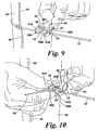
- the second through-bore 33 in the device 24 of Figures 1 to 6 is perpendicular to the first through-bore 26; thus this device can be affixed to a horizontal wire 37 of a stock-fence by presenting the notch 34 to the wire (as shown in Figure 7 ) and then turning the device (as shown in Figure 8 ) so as to enable the horizontal wire to pass through both slots 36A, 36B and become aligned within the remainder of the second through-bore 33 (as can be seen in Figure 9 ), whereby the device is affixed to the wire 37 by the oppositely facing hooks 35A, 35B.
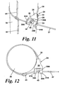
- a free end 38 of the horizontal wire is shown in Figure 10 being inserted into the first through-bore 26 after passing round an end post 39, whereafter surplus wire can be cropped off at 40 between the hooks 35A, 35B (see Figures 11 and 12 ), the end 38 of the horizontal wire 37 being able to pass beyond the portion of horizontal wire aligned with the second through-bore 33 by virtue of the through-bores 26, 33 lying in separate planes.
- Tensioning of the horizontal wire 37 about the end post 39 may be effected by applying a tensioning tool (not shown) to the free end 38 before cropping-off surplus wire or it may be effected when it has been connected to a corresponding horizontal wire in a successive length of stock fence (not shown) by a connecting and tensioning device (not shown) of the type having parallel through-bores each of which has associated wedging means preventing withdrawal of wires inserted from opposite directions, e.g. a GRIPPLE® device.
- Figure 12 shows that there is only one vertical wire 44 above and below the horizontal wire 37 between the device 24 and the end post 39 (but there could be two or more), which, in the absence of the notch 34 and slots 36A, 36B in the body 25, would have had to be removed to enable the horizontal wire 37 to be passed through the uninterrupted second bore, then round the end post, and back to and through the first through-bore with wedging means.
- the hooks 35A, 35B are stiffened by integral around flanges 41A, 41 B, which together with the indented flanks 32 of the body 25 help to minimise the weight of material needed in the body without sacrificing its strength.
- a small hole 42 is provided alongside the entry end 43 of the first through-bore 26 (see particularly Figure 6 ) to enable a rod to be inserted to push the roller 27 against the urge of the spring 28, to enable the wire end 38 to be released if it is necessary to disconnect the stock fence from the end post 39.
Landscapes
- Engineering & Computer Science (AREA)
- General Engineering & Computer Science (AREA)
- Mechanical Engineering (AREA)
- Fencing (AREA)
- Processing Of Terminals (AREA)
- Wire Processing (AREA)
- Electrical Discharge Machining, Electrochemical Machining, And Combined Machining (AREA)
- Catching Or Destruction (AREA)
- Housing For Livestock And Birds (AREA)
Claims (7)
- Dispositif de terminaison de fil du type comportant un corps (25) avec un premier alésage traversant (26) dans lequel des moyens de calage (27) font saillie, poussés par des moyens formant ressort (28), et comportant un deuxième alésage traversant (33) sans moyens de calage, le deuxième alésage traversant (33) étant interrompu par une encoche transversale (34) dans le corps d'une largeur proportionnée au diamètre des fils horizontaux d'une clôture pour bétail avec laquelle le dispositif est destiné à être utilisé, caractérisé en ce que chaque partie (35A, 35B) du corps séparée par l'encoche est pourvue d'une fente d'entrée longitudinale (36A, 36B) dans le deuxième alésage traversant proportionnelle au diamètre desdits fils horizontaux, la fente (36A) dans une partie (35A) étant du côté du corps opposé à la fente (36B) dans l'autre partie (35B).
- Dispositif de terminaison de fil selon la revendication 1, caractérisé en ce que le deuxième alésage traversant (33) est parallèle au premier alésage traversant (26).
- Dispositif de terminaison de fil selon la revendication 1, caractérisé en ce que le deuxième alésage traversant (33) est dans le même plan que le premier alésage traversant (26), mais diverge de celui-ci.
- Dispositif de terminaison de fil selon la revendication 1, caractérisé en ce que le deuxième alésage traversant (33) est perpendiculaire au premier alésage traversant (26).
- Dispositif de terminaison de fil selon la revendication 4, caractérisé en ce que les deux alésages (26, 33) se trouvent dans le même plan.
- Dispositif de terminaison de fil selon la revendication 4, caractérisé en ce que les alésages traversants (26, 33) se trouvent dans des plans séparés.
- Dispositif de terminaison de fil selon l'une quelconque des revendications 1 à 6, caractérisé en ce que les parties de corps (25) sont rigidifiées par des rebords intégraux en forme d'arcs.
Applications Claiming Priority (3)
| Application Number | Priority Date | Filing Date | Title |
|---|---|---|---|
| GB0702405A GB0702405D0 (en) | 2007-02-08 | 2007-02-08 | Wire termination device |
| GB0716424A GB0716424D0 (en) | 2007-08-23 | 2007-08-23 | Wire termination device |
| PCT/GB2008/000391 WO2008096116A1 (fr) | 2007-02-08 | 2008-02-05 | Dispositif de raccord de fil |
Publications (2)
| Publication Number | Publication Date |
|---|---|
| EP2109723A1 EP2109723A1 (fr) | 2009-10-21 |
| EP2109723B1 true EP2109723B1 (fr) | 2012-01-25 |
Family
ID=39204211
Family Applications (1)
| Application Number | Title | Priority Date | Filing Date |
|---|---|---|---|
| EP08702051A Active EP2109723B1 (fr) | 2007-02-08 | 2008-02-05 | Dispositif de raccord de fil |
Country Status (13)
| Country | Link |
|---|---|
| US (1) | US20100038611A1 (fr) |
| EP (1) | EP2109723B1 (fr) |
| AT (1) | ATE542972T1 (fr) |
| AU (1) | AU2008212718B2 (fr) |
| BR (1) | BRPI0807113B1 (fr) |
| CA (1) | CA2676420C (fr) |
| DK (1) | DK2109723T3 (fr) |
| ES (1) | ES2379025T3 (fr) |
| GB (1) | GB2446501B (fr) |
| MX (1) | MX2009008020A (fr) |
| NZ (1) | NZ578538A (fr) |
| PT (1) | PT2109723E (fr) |
| WO (1) | WO2008096116A1 (fr) |
Families Citing this family (16)
| Publication number | Priority date | Publication date | Assignee | Title |
|---|---|---|---|---|
| US8578566B2 (en) * | 2007-10-31 | 2013-11-12 | Thomas & Betts International, Inc. | Cable gripping device |
| US8001660B2 (en) * | 2007-10-31 | 2011-08-23 | Thomas & Betts International, Inc | Cable gripping device |
| EP2213905B1 (fr) * | 2009-01-28 | 2015-09-09 | Thomas & Betts International, Inc. | Dispositif de blocage de câble |
| NL2002914C2 (nl) * | 2009-05-22 | 2010-11-23 | Iac B V | Adapter voor bevestiging aan een elastisch koord voor koppeling van hulpstukken. |
| ES2372195B1 (es) * | 2010-04-28 | 2012-12-13 | Shiny Works, S.L. | Dispositivo de sujeción de objetos mediante elementos filiformes. |
| ES2388278B1 (es) * | 2011-03-15 | 2013-06-17 | Pracer Perfiladores S.L.L. | Elemento de retención para cables tensados. |
| US9103408B1 (en) * | 2011-04-05 | 2015-08-11 | John E. Franta | Soft snatch block |
| GB2492621B (en) * | 2011-07-08 | 2014-05-21 | Gripple Ltd | Gripping arrangement and gripping assembly |
| CZ23927U1 (cs) * | 2012-04-24 | 2012-06-04 | Sybera@Stanislav | Posuvný hácek gumového lana k upevnení predmetu |
| GB2535605B (en) | 2014-12-23 | 2018-04-18 | Gripple Ltd | Clamping devices for retaining elongate members on support arrangements |
| ES2641966B1 (es) * | 2016-04-13 | 2018-08-29 | Shiny Works, S.L. | Tensor terminal con saliente de protección |
| ES2677104B1 (es) * | 2016-12-28 | 2019-05-14 | Shiny Works S L | Dispositivo de terminacion de alambre |
| US10570991B2 (en) * | 2017-02-08 | 2020-02-25 | Michael Aaron O'Rourke | Apparatus for quickly securing a cable |
| GB2577161B (en) * | 2018-08-24 | 2021-05-05 | Gripple Ltd | Connecting device |
| ES2887632B2 (es) * | 2020-06-22 | 2022-05-06 | Fontanillo Esteban Esparza | Dispositivo de amarre de cables o similares en tension |
| EP4189269A4 (fr) | 2020-07-29 | 2024-12-11 | Ctking, LLC | Ensemble boulon en u flexible |
Family Cites Families (9)
| Publication number | Priority date | Publication date | Assignee | Title |
|---|---|---|---|---|
| US774295A (en) * | 1904-04-25 | 1904-11-08 | Ezekiel Wheeler | Fence-wire-fastening device. |
| GB899245A (en) * | 1957-12-11 | 1962-06-20 | William George Frederick Westb | Improvements in and relating to tow-ropes |
| IT1107513B (it) * | 1978-10-26 | 1985-11-25 | Pal Di Dona Alessandro & C S N | Dispositivo autobloccante per corde,trecce,cavi e simili particolarmente sollecitati alla trazione |
| CA1279463C (fr) * | 1983-05-25 | 1991-01-29 | Scarr, Roger J. | Crochet |
| NZ215246A (en) * | 1986-02-21 | 1988-02-12 | Itw New Zealand Ltd | Fencewire clip; opposed pairs pressed together clamp onto post and retain wire |
| US5058847A (en) * | 1990-06-19 | 1991-10-22 | Arakawa & Co., Ltd. | Hanging holder and hanging structure including same |
| GB9814425D0 (en) * | 1998-07-04 | 1998-09-02 | Gripple Ltd | Devices for clamping wires etc. |
| GB2378213B (en) * | 2001-08-01 | 2004-01-14 | Gripple Ltd | Wire or like connectors/tensioners |
| DE20302616U1 (de) * | 2003-02-17 | 2003-05-08 | Stas, Marinus Barbara A.M., Hapert | Bilderhaken |
-
2008
- 2008-02-05 ES ES08702051T patent/ES2379025T3/es active Active
- 2008-02-05 AT AT08702051T patent/ATE542972T1/de active
- 2008-02-05 GB GB0802037A patent/GB2446501B/en active Active
- 2008-02-05 WO PCT/GB2008/000391 patent/WO2008096116A1/fr not_active Ceased
- 2008-02-05 MX MX2009008020A patent/MX2009008020A/es active IP Right Grant
- 2008-02-05 NZ NZ578538A patent/NZ578538A/en unknown
- 2008-02-05 US US12/523,806 patent/US20100038611A1/en not_active Abandoned
- 2008-02-05 BR BRPI0807113A patent/BRPI0807113B1/pt active IP Right Grant
- 2008-02-05 DK DK08702051.7T patent/DK2109723T3/da active
- 2008-02-05 AU AU2008212718A patent/AU2008212718B2/en active Active
- 2008-02-05 PT PT08702051T patent/PT2109723E/pt unknown
- 2008-02-05 CA CA2676420A patent/CA2676420C/fr active Active
- 2008-02-05 EP EP08702051A patent/EP2109723B1/fr active Active
Also Published As
| Publication number | Publication date |
|---|---|
| GB0802037D0 (en) | 2008-03-12 |
| MX2009008020A (es) | 2009-08-07 |
| AU2008212718B2 (en) | 2012-06-07 |
| ES2379025T3 (es) | 2012-04-20 |
| US20100038611A1 (en) | 2010-02-18 |
| EP2109723A1 (fr) | 2009-10-21 |
| ATE542972T1 (de) | 2012-02-15 |
| BRPI0807113A2 (pt) | 2014-11-11 |
| GB2446501A (en) | 2008-08-13 |
| CA2676420A1 (fr) | 2008-08-14 |
| GB2446501B (en) | 2010-10-06 |
| PT2109723E (pt) | 2012-02-08 |
| DK2109723T3 (da) | 2012-04-10 |
| CA2676420C (fr) | 2014-09-16 |
| BRPI0807113B1 (pt) | 2019-01-15 |
| WO2008096116A1 (fr) | 2008-08-14 |
| AU2008212718A1 (en) | 2008-08-14 |
| NZ578538A (en) | 2011-08-26 |
Similar Documents
| Publication | Publication Date | Title |
|---|---|---|
| EP2109723B1 (fr) | Dispositif de raccord de fil | |
| US7930805B2 (en) | Retained tension multiple ball lock cable tie | |
| AU695333B2 (en) | Cable tie having an improved strap locking device | |
| US20040195556A1 (en) | Wire or like connectors/tensioners | |
| WO2010138381A1 (fr) | Dispositif de fixation d'un câble dans des configurations multiples et procédé d'utilisation de celui-ci | |
| WO2008150990A1 (fr) | Attache de câble ayant une réduction de force de fil de bande | |
| WO2010012989A1 (fr) | Dispositif de suspension | |
| CZ20003361A3 (en) | Dead-end clamp for an insulated overhead cable, especially a bundle assembled overhead cable | |
| US7234283B2 (en) | Knot of a retaining net | |
| EP2851572B1 (fr) | Mousqueton pour l'escalade avec levier à câble | |
| US4134575A (en) | Spreader for the wires of a multi-strand wire fence | |
| US20060054386A1 (en) | Connector for a safety cable | |
| US20030070263A1 (en) | Cable tie style tail with improved grip | |
| AU6407390A (en) | Wire puller | |
| JP2006200744A (ja) | ロープブレーキ装置 | |
| AU596727B2 (en) | A wire connector | |
| US381496A (en) | Fence | |
| EP3470614B1 (fr) | Élément pour le blocage de cordon | |
| AU2017100567A4 (en) | A Connecting Assembly | |
| AU2016267396B2 (en) | A drill attachment | |
| EP0864265B1 (fr) | Dispositif de retenue d'un bouton d'oreille | |
| EP0146327A2 (fr) | Manche pour fil | |
| DE202005018133U1 (de) | Halter zur Befestigen eines Kabelbandes o.dgl. | |
| WO2009040327A2 (fr) | Boucle de serrage pour un moyen de tension | |
| KR20100011046A (ko) | 와이어로프 클립 |
Legal Events
| Date | Code | Title | Description |
|---|---|---|---|
| PUAI | Public reference made under article 153(3) epc to a published international application that has entered the european phase |
Free format text: ORIGINAL CODE: 0009012 |
|
| 17P | Request for examination filed |
Effective date: 20090908 |
|
| AK | Designated contracting states |
Kind code of ref document: A1 Designated state(s): AT BE BG CH CY CZ DE DK EE ES FI FR GB GR HR HU IE IS IT LI LT LU LV MC MT NL NO PL PT RO SE SI SK TR |
|
| AX | Request for extension of the european patent |
Extension state: AL BA MK RS |
|
| REG | Reference to a national code |
Ref country code: DE Ref legal event code: R079 Ref document number: 602008012872 Country of ref document: DE Free format text: PREVIOUS MAIN CLASS: F16G0011040000 Ipc: E04H0017260000 |
|
| GRAP | Despatch of communication of intention to grant a patent |
Free format text: ORIGINAL CODE: EPIDOSNIGR1 |
|
| RIC1 | Information provided on ipc code assigned before grant |
Ipc: F16G 11/14 20060101ALI20110826BHEP Ipc: A01K 3/00 20060101ALI20110826BHEP Ipc: E04H 17/26 20060101AFI20110826BHEP Ipc: F16G 11/04 20060101ALI20110826BHEP |
|
| GRAS | Grant fee paid |
Free format text: ORIGINAL CODE: EPIDOSNIGR3 |
|
| GRAA | (expected) grant |
Free format text: ORIGINAL CODE: 0009210 |
|
| AK | Designated contracting states |
Kind code of ref document: B1 Designated state(s): AT BE BG CH CY CZ DE DK EE ES FI FR GB GR HR HU IE IS IT LI LT LU LV MC MT NL NO PL PT RO SE SI SK TR |
|
| AX | Request for extension of the european patent |
Extension state: AL BA MK RS |
|
| REG | Reference to a national code |
Ref country code: GB Ref legal event code: FG4D |
|
| REG | Reference to a national code |
Ref country code: CH Ref legal event code: EP Ref country code: CH Ref legal event code: NV Representative=s name: KIRKER & CIE S.A. |
|
| REG | Reference to a national code |
Ref country code: PT Ref legal event code: SC4A Free format text: AVAILABILITY OF NATIONAL TRANSLATION Effective date: 20120131 |
|
| REG | Reference to a national code |
Ref country code: AT Ref legal event code: REF Ref document number: 542972 Country of ref document: AT Kind code of ref document: T Effective date: 20120215 |
|
| REG | Reference to a national code |
Ref country code: IE Ref legal event code: FG4D |
|
| REG | Reference to a national code |
Ref country code: DE Ref legal event code: R096 Ref document number: 602008012872 Country of ref document: DE Effective date: 20120322 |
|
| REG | Reference to a national code |
Ref country code: NO Ref legal event code: T2 Effective date: 20120125 |
|
| REG | Reference to a national code |
Ref country code: SE Ref legal event code: TRGR |
|
| REG | Reference to a national code |
Ref country code: DK Ref legal event code: T3 |
|
| REG | Reference to a national code |
Ref country code: ES Ref legal event code: FG2A Ref document number: 2379025 Country of ref document: ES Kind code of ref document: T3 Effective date: 20120420 |
|
| REG | Reference to a national code |
Ref country code: NL Ref legal event code: T3 |
|
| LTIE | Lt: invalidation of european patent or patent extension |
Effective date: 20120125 |
|
| PG25 | Lapsed in a contracting state [announced via postgrant information from national office to epo] |
Ref country code: HR Free format text: LAPSE BECAUSE OF FAILURE TO SUBMIT A TRANSLATION OF THE DESCRIPTION OR TO PAY THE FEE WITHIN THE PRESCRIBED TIME-LIMIT Effective date: 20120125 Ref country code: LT Free format text: LAPSE BECAUSE OF FAILURE TO SUBMIT A TRANSLATION OF THE DESCRIPTION OR TO PAY THE FEE WITHIN THE PRESCRIBED TIME-LIMIT Effective date: 20120125 Ref country code: IS Free format text: LAPSE BECAUSE OF FAILURE TO SUBMIT A TRANSLATION OF THE DESCRIPTION OR TO PAY THE FEE WITHIN THE PRESCRIBED TIME-LIMIT Effective date: 20120525 Ref country code: BG Free format text: LAPSE BECAUSE OF FAILURE TO SUBMIT A TRANSLATION OF THE DESCRIPTION OR TO PAY THE FEE WITHIN THE PRESCRIBED TIME-LIMIT Effective date: 20120425 |
|
| REG | Reference to a national code |
Ref country code: GB Ref legal event code: S29 Free format text: OFFER FILED; APPLICATION FILED ON 6 JUNE 2012 |
|
| PG25 | Lapsed in a contracting state [announced via postgrant information from national office to epo] |
Ref country code: PL Free format text: LAPSE BECAUSE OF FAILURE TO SUBMIT A TRANSLATION OF THE DESCRIPTION OR TO PAY THE FEE WITHIN THE PRESCRIBED TIME-LIMIT Effective date: 20120125 Ref country code: FI Free format text: LAPSE BECAUSE OF FAILURE TO SUBMIT A TRANSLATION OF THE DESCRIPTION OR TO PAY THE FEE WITHIN THE PRESCRIBED TIME-LIMIT Effective date: 20120125 Ref country code: GR Free format text: LAPSE BECAUSE OF FAILURE TO SUBMIT A TRANSLATION OF THE DESCRIPTION OR TO PAY THE FEE WITHIN THE PRESCRIBED TIME-LIMIT Effective date: 20120426 Ref country code: LV Free format text: LAPSE BECAUSE OF FAILURE TO SUBMIT A TRANSLATION OF THE DESCRIPTION OR TO PAY THE FEE WITHIN THE PRESCRIBED TIME-LIMIT Effective date: 20120125 |
|
| PGFP | Annual fee paid to national office [announced via postgrant information from national office to epo] |
Ref country code: GB Payment date: 20120525 Year of fee payment: 5 |
|
| PG25 | Lapsed in a contracting state [announced via postgrant information from national office to epo] |
Ref country code: CY Free format text: LAPSE BECAUSE OF FAILURE TO SUBMIT A TRANSLATION OF THE DESCRIPTION OR TO PAY THE FEE WITHIN THE PRESCRIBED TIME-LIMIT Effective date: 20120125 Ref country code: MC Free format text: LAPSE BECAUSE OF NON-PAYMENT OF DUE FEES Effective date: 20120229 |
|
| PG25 | Lapsed in a contracting state [announced via postgrant information from national office to epo] |
Ref country code: EE Free format text: LAPSE BECAUSE OF FAILURE TO SUBMIT A TRANSLATION OF THE DESCRIPTION OR TO PAY THE FEE WITHIN THE PRESCRIBED TIME-LIMIT Effective date: 20120125 Ref country code: CZ Free format text: LAPSE BECAUSE OF FAILURE TO SUBMIT A TRANSLATION OF THE DESCRIPTION OR TO PAY THE FEE WITHIN THE PRESCRIBED TIME-LIMIT Effective date: 20120125 Ref country code: RO Free format text: LAPSE BECAUSE OF FAILURE TO SUBMIT A TRANSLATION OF THE DESCRIPTION OR TO PAY THE FEE WITHIN THE PRESCRIBED TIME-LIMIT Effective date: 20120125 Ref country code: SI Free format text: LAPSE BECAUSE OF FAILURE TO SUBMIT A TRANSLATION OF THE DESCRIPTION OR TO PAY THE FEE WITHIN THE PRESCRIBED TIME-LIMIT Effective date: 20120125 |
|
| REG | Reference to a national code |
Ref country code: GB Ref legal event code: S29 Free format text: OFFER ACCEPTED; APPLICATION FILED ON 06 JUNE 2012 |
|
| PG25 | Lapsed in a contracting state [announced via postgrant information from national office to epo] |
Ref country code: SK Free format text: LAPSE BECAUSE OF FAILURE TO SUBMIT A TRANSLATION OF THE DESCRIPTION OR TO PAY THE FEE WITHIN THE PRESCRIBED TIME-LIMIT Effective date: 20120125 |
|
| PLBE | No opposition filed within time limit |
Free format text: ORIGINAL CODE: 0009261 |
|
| STAA | Information on the status of an ep patent application or granted ep patent |
Free format text: STATUS: NO OPPOSITION FILED WITHIN TIME LIMIT |
|
| 26N | No opposition filed |
Effective date: 20121026 |
|
| PG25 | Lapsed in a contracting state [announced via postgrant information from national office to epo] |
Ref country code: GB Free format text: LAPSE BECAUSE OF THE APPLICANT RENOUNCES Effective date: 20121107 |
|
| REG | Reference to a national code |
Ref country code: DE Ref legal event code: R097 Ref document number: 602008012872 Country of ref document: DE Effective date: 20121026 |
|
| PG25 | Lapsed in a contracting state [announced via postgrant information from national office to epo] |
Ref country code: MT Free format text: LAPSE BECAUSE OF FAILURE TO SUBMIT A TRANSLATION OF THE DESCRIPTION OR TO PAY THE FEE WITHIN THE PRESCRIBED TIME-LIMIT Effective date: 20120125 |
|
| PG25 | Lapsed in a contracting state [announced via postgrant information from national office to epo] |
Ref country code: LU Free format text: LAPSE BECAUSE OF NON-PAYMENT OF DUE FEES Effective date: 20120205 |
|
| PG25 | Lapsed in a contracting state [announced via postgrant information from national office to epo] |
Ref country code: HU Free format text: LAPSE BECAUSE OF FAILURE TO SUBMIT A TRANSLATION OF THE DESCRIPTION OR TO PAY THE FEE WITHIN THE PRESCRIBED TIME-LIMIT Effective date: 20080205 |
|
| REG | Reference to a national code |
Ref country code: FR Ref legal event code: PLFP Year of fee payment: 9 |
|
| REG | Reference to a national code |
Ref country code: FR Ref legal event code: PLFP Year of fee payment: 10 |
|
| REG | Reference to a national code |
Ref country code: FR Ref legal event code: PLFP Year of fee payment: 11 |
|
| P01 | Opt-out of the competence of the unified patent court (upc) registered |
Effective date: 20230523 |
|
| REG | Reference to a national code |
Ref country code: CH Ref legal event code: U11 Free format text: ST27 STATUS EVENT CODE: U-0-0-U10-U11 (AS PROVIDED BY THE NATIONAL OFFICE) Effective date: 20260301 |
|
| PGFP | Annual fee paid to national office [announced via postgrant information from national office to epo] |
Ref country code: NL Payment date: 20260218 Year of fee payment: 19 |
|
| PGFP | Annual fee paid to national office [announced via postgrant information from national office to epo] |
Ref country code: SE Payment date: 20260218 Year of fee payment: 19 |
|
| PGFP | Annual fee paid to national office [announced via postgrant information from national office to epo] |
Ref country code: ES Payment date: 20260319 Year of fee payment: 19 |
|
| PGFP | Annual fee paid to national office [announced via postgrant information from national office to epo] |
Ref country code: NO Payment date: 20260217 Year of fee payment: 19 Ref country code: DE Payment date: 20260217 Year of fee payment: 19 Ref country code: DK Payment date: 20260217 Year of fee payment: 19 Ref country code: IE Payment date: 20260218 Year of fee payment: 19 |
|
| PGFP | Annual fee paid to national office [announced via postgrant information from national office to epo] |
Ref country code: AT Payment date: 20260216 Year of fee payment: 19 |
|
| PGFP | Annual fee paid to national office [announced via postgrant information from national office to epo] |
Ref country code: BE Payment date: 20260218 Year of fee payment: 19 Ref country code: IT Payment date: 20260227 Year of fee payment: 19 |
|
| PGFP | Annual fee paid to national office [announced via postgrant information from national office to epo] |
Ref country code: FR Payment date: 20260219 Year of fee payment: 19 |
|
| PGFP | Annual fee paid to national office [announced via postgrant information from national office to epo] |
Ref country code: TR Payment date: 20260204 Year of fee payment: 19 |
|
| PGFP | Annual fee paid to national office [announced via postgrant information from national office to epo] |
Ref country code: CH Payment date: 20260301 Year of fee payment: 19 Ref country code: PT Payment date: 20260129 Year of fee payment: 19 |