EP2110190B1 - Umbördelverfahren und Umbördelvorrichtung - Google Patents
Umbördelverfahren und Umbördelvorrichtung Download PDFInfo
- Publication number
- EP2110190B1 EP2110190B1 EP09165977A EP09165977A EP2110190B1 EP 2110190 B1 EP2110190 B1 EP 2110190B1 EP 09165977 A EP09165977 A EP 09165977A EP 09165977 A EP09165977 A EP 09165977A EP 2110190 B1 EP2110190 B1 EP 2110190B1
- Authority
- EP
- European Patent Office
- Prior art keywords
- hemming
- roller
- moving die
- guide roller
- vehicle
- Prior art date
- Legal status (The legal status is an assumption and is not a legal conclusion. Google has not performed a legal analysis and makes no representation as to the accuracy of the status listed.)
- Ceased
Links
- 238000009957 hemming Methods 0.000 title claims description 302
- 238000000034 method Methods 0.000 title claims description 25
- 238000003825 pressing Methods 0.000 claims description 8
- 230000007246 mechanism Effects 0.000 description 64
- 238000004519 manufacturing process Methods 0.000 description 29
- 238000005452 bending Methods 0.000 description 22
- 238000005096 rolling process Methods 0.000 description 20
- 230000002093 peripheral effect Effects 0.000 description 9
- 238000012545 processing Methods 0.000 description 9
- 238000000638 solvent extraction Methods 0.000 description 6
- 238000006073 displacement reaction Methods 0.000 description 5
- 230000002035 prolonged effect Effects 0.000 description 5
- 238000003466 welding Methods 0.000 description 4
- 230000005489 elastic deformation Effects 0.000 description 3
- 229910000831 Steel Inorganic materials 0.000 description 2
- 230000015572 biosynthetic process Effects 0.000 description 2
- 239000012530 fluid Substances 0.000 description 2
- 239000010959 steel Substances 0.000 description 2
- 230000000694 effects Effects 0.000 description 1
- 238000003780 insertion Methods 0.000 description 1
- 230000037431 insertion Effects 0.000 description 1
- 238000003754 machining Methods 0.000 description 1
- 239000000463 material Substances 0.000 description 1
- 238000011017 operating method Methods 0.000 description 1
- 238000005192 partition Methods 0.000 description 1
- 230000000452 restraining effect Effects 0.000 description 1
- 238000001179 sorption measurement Methods 0.000 description 1
- 230000037303 wrinkles Effects 0.000 description 1
Images


Classifications
-
- B—PERFORMING OPERATIONS; TRANSPORTING
- B21—MECHANICAL METAL-WORKING WITHOUT ESSENTIALLY REMOVING MATERIAL; PUNCHING METAL
- B21D—WORKING OR PROCESSING OF SHEET METAL OR METAL TUBES, RODS OR PROFILES WITHOUT ESSENTIALLY REMOVING MATERIAL; PUNCHING METAL
- B21D39/00—Application of procedures in order to connect objects or parts, e.g. coating with sheet metal otherwise than by plating; Tube expanders
- B21D39/02—Application of procedures in order to connect objects or parts, e.g. coating with sheet metal otherwise than by plating; Tube expanders of sheet metal by folding, e.g. connecting edges of a sheet to form a cylinder
- B21D39/021—Application of procedures in order to connect objects or parts, e.g. coating with sheet metal otherwise than by plating; Tube expanders of sheet metal by folding, e.g. connecting edges of a sheet to form a cylinder for panels, e.g. vehicle doors
-
- B—PERFORMING OPERATIONS; TRANSPORTING
- B21—MECHANICAL METAL-WORKING WITHOUT ESSENTIALLY REMOVING MATERIAL; PUNCHING METAL
- B21D—WORKING OR PROCESSING OF SHEET METAL OR METAL TUBES, RODS OR PROFILES WITHOUT ESSENTIALLY REMOVING MATERIAL; PUNCHING METAL
- B21D19/00—Flanging or other edge treatment, e.g. of tubes
- B21D19/02—Flanging or other edge treatment, e.g. of tubes by continuously-acting tools moving along the edge
- B21D19/04—Flanging or other edge treatment, e.g. of tubes by continuously-acting tools moving along the edge shaped as rollers
- B21D19/043—Flanging or other edge treatment, e.g. of tubes by continuously-acting tools moving along the edge shaped as rollers for flanging edges of plates
-
- B—PERFORMING OPERATIONS; TRANSPORTING
- B21—MECHANICAL METAL-WORKING WITHOUT ESSENTIALLY REMOVING MATERIAL; PUNCHING METAL
- B21D—WORKING OR PROCESSING OF SHEET METAL OR METAL TUBES, RODS OR PROFILES WITHOUT ESSENTIALLY REMOVING MATERIAL; PUNCHING METAL
- B21D39/00—Application of procedures in order to connect objects or parts, e.g. coating with sheet metal otherwise than by plating; Tube expanders
- B21D39/02—Application of procedures in order to connect objects or parts, e.g. coating with sheet metal otherwise than by plating; Tube expanders of sheet metal by folding, e.g. connecting edges of a sheet to form a cylinder
- B21D39/021—Application of procedures in order to connect objects or parts, e.g. coating with sheet metal otherwise than by plating; Tube expanders of sheet metal by folding, e.g. connecting edges of a sheet to form a cylinder for panels, e.g. vehicle doors
- B21D39/023—Application of procedures in order to connect objects or parts, e.g. coating with sheet metal otherwise than by plating; Tube expanders of sheet metal by folding, e.g. connecting edges of a sheet to form a cylinder for panels, e.g. vehicle doors using rollers
-
- B—PERFORMING OPERATIONS; TRANSPORTING
- B25—HAND TOOLS; PORTABLE POWER-DRIVEN TOOLS; MANIPULATORS
- B25J—MANIPULATORS; CHAMBERS PROVIDED WITH MANIPULATION DEVICES
- B25J11/00—Manipulators not otherwise provided for
-
- Y—GENERAL TAGGING OF NEW TECHNOLOGICAL DEVELOPMENTS; GENERAL TAGGING OF CROSS-SECTIONAL TECHNOLOGIES SPANNING OVER SEVERAL SECTIONS OF THE IPC; TECHNICAL SUBJECTS COVERED BY FORMER USPC CROSS-REFERENCE ART COLLECTIONS [XRACs] AND DIGESTS
- Y10—TECHNICAL SUBJECTS COVERED BY FORMER USPC
- Y10T—TECHNICAL SUBJECTS COVERED BY FORMER US CLASSIFICATION
- Y10T29/00—Metal working
- Y10T29/49—Method of mechanical manufacture
- Y10T29/49826—Assembling or joining
- Y10T29/49893—Peripheral joining of opposed mirror image parts to form a hollow body
-
- Y—GENERAL TAGGING OF NEW TECHNOLOGICAL DEVELOPMENTS; GENERAL TAGGING OF CROSS-SECTIONAL TECHNOLOGIES SPANNING OVER SEVERAL SECTIONS OF THE IPC; TECHNICAL SUBJECTS COVERED BY FORMER USPC CROSS-REFERENCE ART COLLECTIONS [XRACs] AND DIGESTS
- Y10—TECHNICAL SUBJECTS COVERED BY FORMER USPC
- Y10T—TECHNICAL SUBJECTS COVERED BY FORMER US CLASSIFICATION
- Y10T29/00—Metal working
- Y10T29/49—Method of mechanical manufacture
- Y10T29/49826—Assembling or joining
- Y10T29/49908—Joining by deforming
- Y10T29/49915—Overedge assembling of seated part
- Y10T29/49922—Overedge assembling of seated part by bending over projecting prongs
-
- Y—GENERAL TAGGING OF NEW TECHNOLOGICAL DEVELOPMENTS; GENERAL TAGGING OF CROSS-SECTIONAL TECHNOLOGIES SPANNING OVER SEVERAL SECTIONS OF THE IPC; TECHNICAL SUBJECTS COVERED BY FORMER USPC CROSS-REFERENCE ART COLLECTIONS [XRACs] AND DIGESTS
- Y10—TECHNICAL SUBJECTS COVERED BY FORMER USPC
- Y10T—TECHNICAL SUBJECTS COVERED BY FORMER US CLASSIFICATION
- Y10T29/00—Metal working
- Y10T29/53—Means to assemble or disassemble
- Y10T29/53709—Overedge assembling means
- Y10T29/53787—Binding or covering
- Y10T29/53791—Edge binding
Definitions
- the present invention relates to a hemming working method and a hemming working apparatus for folding to bend a hem portion of a work by using a work roller, according to the preamble of claims 1 and 2.
- hemming working for folding to bend a flange constituted by erecting a hem portion of a panel in a direction of an inner side of the panel with regard to hem portions of a bonnet, a trunk, a door and a wheel house of an automobile.
- roll hemming working of positioning to hold a panel above a die and folding to bend a flange at an end portion of the panel while pressing a roller thereto.
- the work when the work is constituted by a box structure or the like, the work is highly rigid and bending is not produced, and therefore, a die is not effectively operated at a portion having a clearance and there is a concern of bringing about a wrinkle in a wavy shape at a portion to be hemmed. Further, when a press force of a roller is excessively increased to eliminate a clearance, the work is distorted.
- Document DE 20 2005 005 880 U1 discloses a hemming working apparatus according to the preamble of claim 1.
- the apparatus consists of a folder head including holder, support and slider, supporting a pressure roller, and a counter pressure roller.
- the apparatus further comprises a stable strip-like protection structure, fastened to the body part and forming a roller track for the counter pressure roller.
- the device comprises several pneumatic suction cups positioned along the body part edge.
- Fig.12A and Fig.12B are views for explaining a basic principle of a roller hemming method according to a related art.
- the related art is disclosed in, for example, JP-B-07-090299 .
- a rolling hemming apparatus 8100 is constituted by a lower die 8102 provided with a guide face 8101 and a flat roller 8104 rotatably supported by a robot hand 8103.
- An outer panel 8107 having a flange 8106 is mounted on the lower die 8102, and an inner panel 8108 is mounted on the outer panel 8107. Further, the flat roller 8104 is rotated while being in line with the guide face 8101 to fold to bend the flange 8106 indicated by an imaginary line by about 45° up to a position indicated by a bold line.
- the step is referred to as a tackedly bending step or a primary bending step.
- a direction of the flat roller 8104 is changed by the robot hand 8103. Further, the flange 8106 indicated by an imaginary line is completely folded to bend up to a position indicated by a bold line.
- the step is referred to as a regular bending step or a secondary bending step.
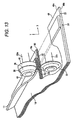
- Fig.13B is a view for explaining a problem of the rolling method of the related art.
- the work 8110 is a bonnet in which a front hem portion 8111 and a rear hem portion 8112 are bent.
- a front end portion 8115 of a flange 8113 becomes remoter from a bending center 8116 than a base portion 8114 of the flange 8113. That is, when a radius of the base portion 8114 is designated notation R1 and a radius of the front end portion 8115 is designated by notation R2, R1 ⁇ R2.
- a peripheral length of the front end portion 8115 becomes larger than a peripheral length of the base portion 8114.
- a similar peripheral length difference is present also at a guide face 8120 shown in Fig.13B .
- a radius of one hem (which is proximate to the bending center) 8121 of the guide face 8120 is designated by notation R3 and a radius of other hem 8122 is designated by notation R4, R3 ⁇ R4.
- R3 a radius of one hem (which is proximate to the bending center) 8121 of the guide face 8120
- R4 a radius of other hem 8122
- a lower die 8124 including the guide face 8120 is constituted by hard steel and also the flat roller 8123 is constituted by hard steel. Therefore, at least one of the guide face 8120 and the flat roller 8123 is worn, and it is difficult to continue hemming working.
- JP-B-07-090299 is not applicable to hemming working constituting an object by the work 8110 in which the front hem portion 8111 and the rear hem portion 8112 are bent.
- FIG.14 is a view for explaining a basic constitution of other related art.
- a hemming apparatus 9100 is constituted by guide cylinders 9103, 9103 fixedly provided at a support member 9102 attached to a front end of a robot arm 9101, slide shafts 9104, 9104 slidably guided to be supported by the guide cylinders 9103, 9103, sliders 9105, 9105 fixed to the slide shafts 9104, 9104, a cylinder 9106 coupled to the sliders 9105, 9105 and fixedly provided to the support member 9102, a hemming roller 9107 axially supported rotatably by the sliders 9105, 9105, a guide roller 9108 axially supported by the support member 9102, a guide rail 9111 for preparatory bending for guiding the guide roller 9108 and provided to a lower die 9109 to be inclined in a lower direction, and a guide rail 9112 for regular bending for guiding the guide roller 9108 and provided to the lower die 9109 vertically in a lower
- the guide roller 9108 is engaged with the guide rail 9112 for regular bending.
- the hemming roller 9107 is disposed in a horizontal direction.
- regular bending working of constituting a pinched state is carried out by folding to bend an end hem 9114 of a lower side sheet 9113 which has been preparatorily bent by 45° over an end hem 9116 of an upper side sheet 9115. Hems of the lower side sheet 9113 and the upper side sheet 9115 can be connected thereby.
- the guide roller 9108 is constituted by a shape similar to that of a flanged wheel, and therefore, when the guide rail 9112 for regular bending is bent abruptly to some degree or more, the guide roller 9108 is derailed. Therefore, the hemming apparatus 9100 of the related art of Fig.39 is applicable only to an end hem 9114 gradually bent in a head and tail direction of the drawing.
- a radius of curvature is an inverse number of a radius.
- a work of a bonnet or the like of a vehicle includes corner portions having large radii of curvature at four corners thereof. Such a work cannot be worked by the hemming apparatus 9100,
- FIG.40 is a view for explaining a basic constitution of still other related art.
- a hemming forming apparatus 9200 is constituted by a jig 9203 for receiving an outer panel 9202 mounted with an inner panel 9201, an articulated robot 9205 mounted on a conveyor apparatus 9204 arranged in a side direction of the jig 9203, a roller holder 9207 attached to a front end of a robot arm 9206 of the articulated 9205, a forming roller 9208 attached to a front end of the roller holder 9207, die driving apparatus 9209 respectively arranged at vicinities of four corner portions of the jig 9203, and forming dies 9211 respectively attached to the die driving apparatus 9209.
- the forming roller 9208 is run by being pressed from an upper side substantially at a linear portion having a small radius of curvature, by pressing to form the four corner portions having large radii of curvature respectively by the forming dies 9211, hemming working can be finished by folding to bend a fold-to-bend portion provided to the outer panel 9202 to the inner panel 9201.
- the hemming forming apparatus 9200 of the related art of Fig.15 the linear portion of the work is worked by the forming roller 9208, and the four corner portions of the work are worked by the forming dies 9211. 4 pieces of the forming dies 9211 are needed, and therefore, the hemming forming apparatus 9200 becomes expensive.
- hemming working is difficult for the portion having a large radius of curvature, and according to the related art of Fig.15 , although hemming working of the portion having the large curvature can be carried out, the hemming apparatus becomes expensive.
- the die by elastically urging the die to the work such that only the portion pressed by the roller can be brought into contact with the die and the die can be separated from the work at other than the pressed portion, the work can firmly be brought into contact with the die at the pressed portion, the hemming portion can be worked to be folded to bend in a pertinent shape, and warping or deformation of the work can be prevented.
- the work is brought into contact with the die and the hemming portion can be worked to be folded to bend in a pertinent shape. Further, by elastically urging the die to the work such that the die can be separated from the work at other than the pressed portion, a clearance is not forcibly crushed and warping or deformation of the work can be prevented.
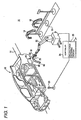
- a hemming working apparatus 10 is an apparatus set to a middle step of a production line 14 for assembling and working a vehicle (work) 12 in a so-to-speak white body state for carrying out roll hemming working for a flange 17 of a wheel arch portion on a left rear wheel side.
- a wheel arch portion 16 is constituted by a shape of a substantially a circular arc of 180°.
- a flange 17 is constituted by a shape of being bent by 90° from an end portion 16a (refer to Fig.6 ) of the wheel arch portion 16 to an inner side.
- the hemming working apparatus 10 includes a moving die 18 to be brought into contact with the wheel arch portion 16 of the vehicle 12 constituting the work, a robot (carrying means) 22 for moving the moving die 18 and including a hemming unit 20 at a front end thereof, an photoelectric sensor 23 for detecting that the vehicle 12 is carried to a predetermined position of the production line 14, and a controller 24 for carrying out a comprehensive control.
- the controller 24 includes a holding force adjusting portion (adjusting means) 25 for adjusting a force for the robot 22 for maintaining an attitude.
- the holding force adjusting portion 25 adjusts a torque generated by each motor by adjusting a voltage applied to a drive circuit for driving the motor provided at each joint of the robot 22. Thereby, the forces generated by the respective joints can uniformly be reduced or increased.
- the robot 22 is of an industrial articulated type and can move the hemming unit 20 to an arbitrary position and in an arbitrary attitude by a programmed operation.
- a vicinity of the robot 22 is provided with a storing base 26 arranged with a plurality of kinds of moving dies 18 in accordance with a kind of the vehicle 12, and a position data of the storing base 26 is stored to the controller 24.
- the controller 24 is connected to an external production control computer (not illustrated) for controlling an operation of the projection line 14, and the controller 24 is supplied with information showing a kind or the like of the vehicle 12 carried on the production line 14.
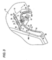
- the hemming unit 20 includes a hemming roller 30 and a guide roller 32 provided to project from an end face, and a chuck 34 provided at a side face portion.
- the chuck 34 includes a pair of fingers 36 opened and closed under an operation of the controller 24, which are used for moving the moving die 18.
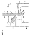
- the hemming roller 30 and the guide roller 32 are axially supported rotatably by support shafts 30a and 32a. Further, the hemming roller 30 and the guide roller 32 can be moved in Y direction (direction of aligning the support shafts 30a and 32a), an interval between the support shaft 30 and the support shaft 32a is adjusted to be able to press a member pinched by the hemming roller 30 and the guide roller 32. Further, the hemming roller 30 and the guide roller 32 are of so-to-speak floating structure, movable in Y direction and X direction (axial directions of the support shafts 30a and 32a) while maintaining positions relative to each other and moving drivenly and elastically by an external force. That is, the support shaft 30 and the support shaft 32a are made to be cooperatively movable in X direction and Y direction while maintaining an adjusted interval therebetween.
- the hemming roller 30 is constituted by a taper roller 38 provided on a front end side, and a circular cylinder roller 40 provided on a base end side by a structure integral with the taper roller 38.
- the taper roller 38 is a frustrum of a circular cone in a converging shape inclined by 45° in a side view thereof, and an edge line length L1 (refer to Fig.6 ) is set to be slightly longer than a height H (refer to Fig.6 ) of the flange 17.
- the circular cylinder roller 40 is constituted by a shape of a cylinder having a diameter slightly larger than a maximum diameter portion on the base end side of the taper roller 38, and a height H2 in an axial direction (refer to Fig.6 ) is set to be slightly smaller than the height H of the flange 17.
- the guide roller 32 is constituted by a shape of a circular disk a surrounding of which is set to a narrow width, and is engageable with a first groove (guide portion) 52 or a second groove (guide portion) 54 (refer to Fig.6 ).
- the moving die 18 is constituted by constituting a base thereof by a die plate 49.
- the die plate 49 is constituted by a shape of a plate and a side thereof brought into contact with the wheel arch portion 16 is referred to as a surface 49a and a face on a side opposed thereto is referred to as a back face 49b to be differentiated from each other.
- a work side in view from the end portion 16a of the wheel arch portion 16 is referred to as an inner side (arrow mark A1 side) and a side opposed thereto is referred to as an outer side (arrow mark A2) to be differentiated from each other.
- the die plate 49 is constituted by a shape of a plate in an arch shape and the surface 49a of which is brought into contact with a surrounding of the wheel arch portion 16, and the surface 49a is set to a three-dimensional curved face in conformity with a shape of a surface of the vehicle 12. Therefore, when the moving die 18 is attached to the wheel arch portion 16, the first groove 52 and the second groove 54 and the flange 17 are arranged in parallel with each other, and the surface 49a is brought into face contact with the vehicle 12 by a wide area.
- the moving die 18 includes an outer side circular arc portion 50 formed along a slightly outer side of an end portion 16a of the wheel arch portion 16, the first groove 52 and the second groove 54 provided in parallel with each other along the outer side circular arc portion 50 at the back face 49b, a knob 56 provided at the back face 49b, three adsorbing mechanisms (mounting means) 58 provided to align at an upper portion thereof, and a pipe 60 for sucking air by way of the adsorbing mechanism 58.
- the first groove 52 is provided on an outer side projected from the end portion 16a of the flange 17 on the die plate 49
- the second groove 54 is provided on an inner side of the end portion 16a.
- the moving die 18 includes 2 pieces of positioning pins 62 respectively projected from both ends of a lower portion of the surface 49a.
- means for mounting the moving die 18 to the wheel arch portion 16 is not limited to the adsorbing mechanism 58 but a clamp mechanism or the like for grabbing a predetermined portion of the vehicle 12 by a lever or the like, or both of the clamp mechanism or the like and the adsorbing mechanism 58 may be used.
- the positioning pin 62 is set to a diameter capable of being inserted into a positioning hole 65 (refer to Fig.1 ) of the vehicle 12, and a front end thereof is contracted in a diameter direction in a taper shape to facilitate insertion. Further, the moving die 18 is supported and fixed mainly by the adsorbing mechanism 58, and therefore, the positioning pin 62 does not need a strength for supporting a self weight of the moving die 18 and is sufficiently constituted by a slender diameter.
- the adsorbing mechanism 58 is provided at a lower stage portion 64 constituted by slightly machining the surface 49a, and includes a gripper 66 having an area suitable for adsorption and a sucking port 68 communicated with the gripper 66.
- the gripper 66 is constituted by a two-layers structure of an adsorbing portion 67a of an elastic member (for example, rubber, sponge or the like) and a base portion 67b harder than the adsorbing portion 67a, and the base portion 67b is fixed to the lower stage portion 64.
- the gripper 66 is slightly projected from the surface 49a.
- the gripper 66 is provided with a number of horizontal holes 70 at a surface thereof.
- the horizontal holes 70 are gathered to the base portion 67b and are communicated with the sucking port 68.
- the sucking port 68 is connected to the pipe 60 by a joint 72.
- a sucking operation is achieved by sucking air from the respective horizontal holes 70 by sucking air from the pipe 60, the gripper 66 can be adsorbed to a surface of the wheel arch portion 16, and the moving die 18 is fixed.
- the adsorbing portion 67a of the gripper 66 is adsorbed by being slightly compressed elastically. Air may be sucked from the pipe 60 by using an ejector or a vacuum pump or the like.
- the moving die 18 is brought into contact with only the surrounding of the wheel arch portion 16, and therefore, the moving die 18 is small-sized. Further, the moving die 18 is brought into contact with the vehicle 12 from the side face, and therefore, the moving die 18 is not applied with a weight of the vehicle 12, and is not constituted by a load resistant structure, and therefore, the moving die 18 is set to be light-weighted. Therefore, the moving die 18 is made to be movable simply and conveniently by the robot 22 by grabbing the knob 56 by the chuck 34 and can be adsorbed by the adsorbing mechanism 58.
- the outer side circular arc portion 50 is arranged on an outer side (lower side of Fig.6 ) of the end portion 16a of the wheel arch portion 16.
- the first groove 52 is arranged slightly on an outer side of the end portion 16a and the second groove 54 is arranged on the inner side of the end portion 16a.
- the first groove 52 and the second groove 54 are arranged in parallel with each other along the end portion 16a at positions substantially symmetrical with each other by constituting a reference by the end portion 16a.
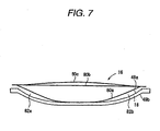
- the wheel arch portion 16 is constituted by a box structure welding 3 sheets of plate members of an outer plate 80a, a middle plate 80b and an inner plate 80c and is highly rigid.
- the welded structure there is a case of producing a clearance from the surface 49a of the moving die 18 by generating a thermal strain by welding.
- Fig.7 there are brought about clearances 82a and 82b between the surface 49a of the moving die 18 and the outer plate 80a of the wheel arch portion 16, center portions thereof are brought into contact with each other and intervals therebetween are respectively widened to both end portions.
- step S1 information of the vehicle kind of the vehicle 12 successively carried from a production control computer is confirmed, thereafter, the robot 22 returns the currently grabbed moving die 18 to a rectified position of the storing base 26, and grabs other moving die 18 in correspondence with the vehicle kind by the chuck 34.
- the hold and change operation is not needed, further, when a plurality of pieces of the vehicles 12 of the same vehicle kind are carried, it is not naturally necessary to hold and change the moving die 18.
- step S2 the operation is at standby until the vehicle 12 is carried by confirming the signal of the photoelectric sensor 23.
- the vehicle 12 is carried by the production line 14 and is stopped at a predetermined position at a vicinity of the robot 22.
- the operation proceeds to step S3 at a time point of confirming carrying of the vehicle 12 by the photoelectric sensor 23.
- step S3 (approaching step), as shown by Fig.10A , positioning in vertical and horizontal directions is carried out by moving the moving die 18 by operating the robot 22 and inserting the positioning pin 62 to the positioning hole 65 of the vehicle 12. At the time point, the surface 49a of the moving die 18 and the gripper 66 are separated from the vehicle 12.
- step S4 as shown by Fig.10B , the moving die 18 is further made to advance and the gripper 66 is brought into light contact with the surface of the vehicle 12 by operating the robot 22. At the time point, the surface 49a of the moving die 18 is slightly separated from the vehicle 12.
- step S5 air is sucked from the pipe 60 and an operation of sucking air by the adsorbing mechanism 58 is started.
- the force of the robot 22 for maintaining the attitude is maintained to be sufficiently larger than an adsorbing force of the adsorbing mechanism 58 and the moving die 18 is not displaced.
- step S6 mounting step
- rigidities of the respective joints of the robot 22 are reduced by reducing the output of the robot 22 under the operation of the holding force adjusting portion 25 to thereby reduce the force for maintaining the attitude.
- the moving die 18 is brought into an elastically displaceable state (so-to-speak floating state).
- the adsorbing force of the adsorbing mechanism 58 of the robot 22 exceeds the force of maintaining the attitude of the robot 22 and the moving die 18 is displaced to the vehicle 12.
- the moving die 18 can be adsorbed to the vehicle 12.
- the moving die 18 is displaced to the front side while elastically compressing the adsorbing portion 67a to bring the surface 49a into contact with the vehicle 12.
- the robot 22 is brought into a floating state, and therefore, the respective joints are pertinently deformed, and the moving die 18 is brought into contact with the vehicle 12 while being displaced to constitute a pertinent attitude of aligning the surface shape to the vehicle 12. Therefore, the moving die 18 does not press the vehicle 12 excessively in a state of not being aligned to the vehicle 12 and the vehicle 12 can be prevented from being deformed. Further, the moving die 18 is attached to be accurately positioned to fix to the wheel arch portion 16.
- the robot 22 supports the self weight of the moving die 18 and the robot 22 per se in the vertical direction even in the floating state, and therefore, the adsorbing mechanism 58 does not need to support the weight but may generate only the force of being adsorbed to the vehicle 12. Therefore, the adsorbing force of the adsorbing mechanism 58 is sufficiently constituted by a lower output. In this way, the low output is set to the adsorbing mechanism 58, and therefore, the vehicle 12 is not pressed excessively and the vehicle 12 can be prevented from being deformed.
- the adsorbing portion 67a for fixing the moving die 18 to the vehicle 12 is constituted by the elastic member, and therefore, the adsorbing portion 67a can firmly be fixed to the surface of the vehicle 12 by being brought into close contact therewith without leaking air, a stress is not locally concentrated and the vehicle 12 can further be prevented from being deformed.
- step S7 the fingers 36 of the chuck 34 are opened, thereafter, the robot 22 and the hemming unit 20 are detached from the moving die 18.
- the moving die 18 is fixed to the vehicle 12 by the adsorbing mechanism 58 integrally provided to the moving die 18, and therefore, even when the chuck 34 is disengaged therefrom, the moving die 18 is not dropped, or a position of which is not shifted.
- step S8 a direction of the hemming unit 20 is changed, thereafter, the hemming unit 20 is made to be proximate to the outer side circular arc portion 50 of the moving die 18 and the guide roller 32 is engaged with the first groove 52.
- step S9 the guide roller 32 and the hemming roller 30 are made to be proximate to each other, and as shown by Fig.6 , the moving die 18 is pinched by the guide roller 32 and the circular cylinder roller 40.
- the flange 17 is pressed by the taper roller 38 and is bent to be inclined by 45° along the cone face.
- step S10 there is continuously carried out a first hemming step of bending the flange 17 to incline by 45° in an inner side direction by rolling the guide roller 32 while being engaged with the first groove 52. That is, there is carried out the first hemming step of rolling the hemming roller 30 and the guide roller 32 while being rotated in directions reverse to each other and continuously bending the flange 17 by the circular cone face of the taper roller 38. Hemming working by the first hemming step is carried out over an entire length of the flange 17.
- the hemming roller 30 and the guide roller 32 are made to advance in an arrow mark X1 direction by slightly prolonging a distance between the hemming roller 30 and the guide roller 32 to be separated from the moving die 18 and advancing the hemming unit 20.
- the advancing distance is a distance equal to a distance between the first groove 52 and the second groove 54.
- the guide roller 32 is engaged with the second groove 54. Further, the guide roller 32 and the hemming roller 30 are made to be proximate to each other, as shown by Fig.12 , the moving die 18 is pinched to press by the guide roller 32 and the cylinder roller 40. The flange 17 is pressed by the circular cylinder roller 40 to be bent to be brought into contact with the back face of the wheel arch portion 16. That is, the flange 17 is bent by 45° further from the first hemming step and by 90° from an initial angle.
- step S13 there is continuously carried out a second hemming step of folding to bend the flange 17 until being brought into contact with the back face of the wheel arch portion 16 by rolling the guide roller 32 while engaging the guide roller 32 with the second groove 54. That is, the second hemming step is carried out by continuously bending the flange 17 by the outer peripheral circular cylinder face of the circular cylinder roller 40 by rolling the hemming roller 30 and the guide roller 32 while rotating the hemming roller 30 and the guide roller 32 in directions reverse to each other.
- the guide roller 32 is moved on an accurate path along the second groove 54 by the floating structure of the hemming roller 30 and the guide roller 32 and working is carried out over the entire length of the flange 17.
- step S14 the distance between the hemming roller 30 and the guide roller 32 is slightly prolonged to be separated from the moving die 18. Further, the hemming unit 20 is temporarily separated from the moving die 18.
- step S15 a processing of opening the moving die 18 is carried out. That is, after changing the direction of the hemming unit 20, the hemming unit 20 is made to be proximate to the back face 49b to grab the knob 56 by the chuck 34, further, sucking by the pipe 60 is finished.
- a standby processing is carried out. That is, the robot 22 is moved to a predetermined standby position to separate the moving die 18 from the vehicle 12.
- the controller 24 informs that the hemming working has been finished normally to the production control computer.
- the informed production control computer confirms that a condition is established with regard to other predetermined requirement and drives the production line 14 to carry the vehicle 12 finished with the hemming working to a next step.
- the moving die 18 is made to be elastically deformable by bringing the robot 22 into the floating state, and the moving die 18 is brought into contact with the vehicle 12 by the adsorbing mechanism 58.
- the rigidities of the respective joints of the robot 22 are reduced, and therefore, the respective joints are pertinently deformed, and the moving die 18 is brought into contact with the work while being displaced to constitute the pertinent attitude of aligning the surface shape thereto. Therefore, the moving die 18 does not excessively press the vehicle 12 in the state of not being aligned threreto and the vehicle 12 can be prevented from being deformed.
- the floating step can be constituted by high speed by setting the robot 22 to the large output, and the work can be prevented from being deformed in the contact step by setting the adsorbing mechanism 58 to the relatively low output.
- the moving die 18 is constituted by the weight to a degree of capable of being carried by the robot 22 and is generally applicable to other than the vehicle 12 regardless of the size of the work. Further, the moving die 18 is applicable also on the production line 14, and therefore, it is not necessary to provide a space exclusive for the hemming working separately from the production line 14.
- one piece of the robot 22 is made to serve the means for carrying the moving die 18 and the means for moving the hemming unit 20, a function as the carrying means of the moving die 18 and a function as the moving means of the hemming unit 20 may respectively distributed to individual robots.
- a system of folding to bend the flange 17 is not limited to a system of folding to bend the flange 17 to an inner side but the flange 17 may be folded to bend to pinch a predetermined inner panel or the like.
- FIG.14 Processings shown in Fig.14 are carried out by the moving die 18, the hemming unit 20 and the robot 22 mainly under the control by the controller 24.
- three of the grippers 66 are differentiated to describe as the grippers 66a, 66b and 66c as necessary (refer to Fig.15 ).
- step S201 the information of the vehicle kind of the vehicle 12 successively carried from the production control computer is confirmed, thereafter, the robot 22 returns the currently grabbed moving die 18 to a rectified position of the moving base 26 and grabs the other moving die 18 in correspondence with the vehicle kind by the chuck 34.
- the hold and change operation is not needed, further, when a plurality of pieces of the vehicles 12 of the same vehicle kind are continuously carried, it is not naturally necessary to hold and change the moving die 18.
- step S202 the operation is at standby until the vehicle 12 is carried by confirming the signal of the photoelectric sensor 23.
- the vehicle 12 is carried by the production line 14 and is stopped at a predetermined position at a vicinity of the robot 22.
- the operation proceeds to step S203 and the time point of confirming carrying of the vehicle 12 by the photoelectric sensor 23.
- the moving die 18 is mounted to the wheel arch portion 16. That is, the moving die 18 is moved by operating the robot 22, and positioned in the vertical and horizontal directions by inserting the positioning pin 62 into the positioning hole 65 of the vehicle 12, thereafter, the moving die 18 is further advanced and the gripper 66 is brought into light contact with the surface of the vehicle 12.
- the robot 22 reduces the force of holding the moving die 18 to make the moving die 18 elastically displaceable relative to the vehicle 12, thereafter, air is sucked from the pipe 60 to bring the surface 49a of the moving die 18 into contact with the vehicle 12 by the adsorbing mechanism 58. Thereby, the moving die 18 is attached to the wheel arch portion 16 and accurately positioned to fix.
- step S204 after opening the fingers 36 of the chuck 34, the robot 22 and the hemming unit 20 are detached from the moving die 18.
- the moving die 18 is fixed to the vehicle 12 by the adsorbing mechanism 58 integrally provided to the moving die 18, and therefore, even when the chuck 34 is disengaged, the moving die 18 is not dropped, or a position thereof is not shifted.
- a direction of the hemming unit 20 is changed, thereafter, the hemming unit 20 is made to be proximate to the outer side circular arc portion 50 of the moving die 18, and the guide roller 32 is engaged with the one end portion 52a of the first groove 52.
- step S206 the guide roller 32 and the hemming roller 30 are made to be proximate to each other, and as shown by Fig.6 , the moving die 18 is pinched by the guide roller 32 and the circular cylinder roller 40. At this occasion, the flange 17 is bent by being inclined by 45° along the cone face by being pressed by the taper roller 38.
- the guide roller 32 and the hemming roller 30 strongly attract each other, and therefore, as shown by Fig.16 , at the one end portion 52a of the first groove 52, the surface 49a and the outer plate 80a are brought into contact with each other without a clearance therebetween and the flange 17 is firmly folded to bend. In contrast thereto, at a center portion 52b and the other end portion 52c of the first groove 52, there is produced a clearance 94a widened in accordance with a distance from the one end portion 52a.
- step S207 there is continuously carried out the first hemming step of inclining the flange 17 by 45° in the inner side direction to bend by rolling the roller 32 while engaging the guide roller 32 with the first groove 52. That is, there is carried out the first hemming step of rolling the hemming roller 30 and the guide roller 32 while being rotated in directions reverse to each other and continuously bending the flange 17 by the conical face of the taper roller 38.
- the gripper 66b at the center proximate to the center portion 52b is considerably compressed and the clearance 94b of the portion becomes very narrow.
- the clearances 94a and 94c of portions in correspondence with the grippers 66a and 66c are widened in accordance with the distance from the center portion 52b.
- the guide roller 32 reaches the end portion 52c on the finish side, the end portion 52c is pinched by the guide roller 32 and the hemming roller 30, the surface 49a and the outer plate 80a are brought into contact with each other without a clearance therebetween, the flange 17 is firmly folded to bend and a clearance 90d at the end portion 52a and the center portion 52b.
- the gripper 66c proximate to the end portion 52c is considerably compressed and the clearance 94c of the portion becomes very narrow.
- the clearances 94a and 94b of the portions in correspondence with the grippers 66a and 66b are widened in accordance with the distance from the end portion 52c.
- the hemming working by the first hemming step is carried out over the entire length of the flange 17.
- the outer plate 80a and the surface 49a are brought into contact with each other without a clearance therebetween at a portion of being pinched by the guide roller 32 and the hemming roller 30, and therefore, the flange 17 is firmly folded to bend.
- the surface 49a is brought into contact with the outer plate 80a by being moved based on elastic deformation of the gripper 66, and therefore, an excessive outer force is not exerted to the outer plate 80a and the middle plate 80b and the inner plate 80c and a distortion or a deformation is not brought about.
- the portion at which the surface 49a of the moving die 18 and the outer plate 80a are brought into contact with each other is only the working portion pinched by the guide roller 32 and the hemming roller 30, and at the other portion, the surface 49a and the outer plate 80a are maintained in a separated state by achieving a cushioning operation by the gripper 66. Therefore, a scratch or the like can be prevented from being attached to the outer plate 80a.
- a distance between the hemming roller 30 and the guide roller 32 are slightly prolonged to be separated from the moving die 18, further, the hemming roller 30 and the guide roller 32 are made to advance in an arrow mark X1 direction by advancing the hemming unit 20.
- the advancing distance is a distance equal to the distance between the first groove 52 and the second groove 54.
- the guide roller 32 is engaged with the second groove 54. Further, the guide roller 52 and the hemming roller 30 are made to be proximate to each other, as shown by Fig.23 , the moving die 18 is pinched to press by the guide roller 32 and the circular cylinder roller 40.
- the flange 1 is pressed by the circular cylinder roller 40 to be bent to be brought into contact with the back face of the wheel arch portion 16. That is, the flange 17 is bent further by 45° from the first hemming step and by 90° from the initial angle.
- step S210 there is continuously carried out the second hemming step of folding to bend the flange 17 to be brought into contact with the back face of the wheel arch portion 16 by rolling the guide roller 32 while engaging the guide roller 32 with the second groove 54. That is, the second hemming step is carried out by continuously bending the flange 17 by the outer peripheral circular cylinder face of the circular cylinder roller 40 by rolling the hemming roller 30 and the guide roller 32 while being rotated in directions reverse to each other.
- an effect similar to the first hemming step is achieved also with regard to the second hemming step although illustration thereof is omitted. That is, at a portion of being pinched by the guide roller 32 and the hemming roller 30, the outer plate 80 and the surface 49a are brought into contact with each other without a clearance therebetween and the flange 17 is firmly bent by 90° from the initial angle, further, the surface 49a is moved based on the elastic deformation of the gripper 66 to be brought into contact with the outer plate 80a, and therefore, a distortion or a deformation is not brought about at the outer plate 80a and the middle plate 80b and the inner plate 80c. Further, at other than the working portion, the outer plate 80a and the surface 49a are maintained in a separated state by achieving the cushioning operation by the gripper 66 and a scratch or the like can be prevented from being attached to the outer plate 80a.
- the distance between the hemming roller 30 and the guide roller 32 is slightly prolonged to be separated from the moving die 18. Further, the hemming unit 20 is temporarily separated from the moving die 18.
- step S212 a processing of opening the moving die 18 is carried out. That is, the direction of the hemming unit 20 is changed, thereafter, the hemming unit 20 is made to be proximate to the rear face 49b, the knob 56 is grabbed by the chuck 34, further, sucking of the pipe 60 is finished.
- a standby processing is carried out at step S213. That is, the moving die 18 is separated from the vehicle 12 by moving the robot 22 to a predetermined standby position.
- the controller 24 informs that the hemming working has normally been finished to the production control computer.
- the informed production control computer confirms that a condition is established with regard to other predetermined requirement and drives the production line 14 to carry the vehicle 12 finished with the hemming working to a next step.
- the hemming portion 16 constituting the work is constituted by a shape having an error relative to the moving die 18, at the working portion by the hemming roller 30 and the guide roller 32, the hemming portion can be folded to bend by the pertinent shape by bringing the surface of the wheel arch portion 16 into contact with the surface 49a of the moving die 18.
- the gripper 66 is constituted by the elastic member, and therefore, the moving die 18 is elastically urged to the wheel arch portion 16 to be able to separate the moving die 18 from the wheel arch portion at other than the pressing portion, the clearance is not forcibly crushed, and a distortion or a deformation of the outer plate 80a, the middle plate 80b and the inner plate 80c can be prevented.
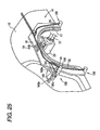
- the means for elastically mounting the moving die 18 to the vehicle 12 is not limited to a case of providing the means between the moving die 18 and the vehicle 12 as in the adsorbing portion 67a but, for example, a plurality of clamp mechanisms 158 as shown by Fig.25 may be used in accordance with a shape, a material or the like of the work.
- the clamp mechanism 158 includes a stay 164 extended from an end portion of the die plate 49, a cylinder 166 pivotably provided to the stay 164, and an opening/closing lever 168 inclined centering on a support shaft provided at the stay 164.
- One end of the opening/closing lever 168 constitutes a grip portion 168a engaged with and held by a reference position of the vehicle 12.
- the grip portion 168a of the elastic member similar to the adsorbing portion 67a, the moving die 18 can elastically be urged to the vehicle 12 to be able to bring the moving die 18 into contact with the wheel arch portion 16 at the working portion by the hemming roller 30 and separate the moving die 18 from the wheel arch portion 16 at other than the pressing portion.
- Both of the clamp mechanism 158 and the adsorbing mechanism 58 may be used.
- one piece of the robot 22 is made to be serve the means for carrying the moving die 18 and the means for moving the moving unit 20, a function as the carrying means of the moving die 18 and a function as the moving means of the hemming unit 20 may respectively distributed to individual robots.
- the system of folding to bend the flange 17 is not limited to the system of folding to bend the flange 17 simply to the inner side but the flange 17 may be folded to bend to pinch a predetermined inner panel or the like.
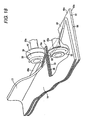
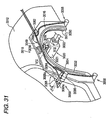
- FIG.26 is an outline perspective view for explaining a behavior of carrying out hemming working for a flange of a wheel arch portion of a vehicle by a hemming working apparatus according to a second exemplary embodiment of the invention.
- a hemming working apparatus 3010 according to the second exemplary embodiment is an apparatus set to a middle step of a production line 3014 for assembling and working a vehicle 3012 as a work in a so-to-speak white body for carrying out hemming working for a flange 3017 of a wheel arch portion 3016 on a left rear wheel side.
- the wheel arch portion 3016 is constituted by a shape of substantially a circular arc of about 180°.
- the flange 3017 is constituted by a shape of being bent by 90° from an end portion 3016a (refer to two-dotted chain line of Fig. 30 ) of the wheel arch portion 3016 to an inner side by 90°.
- the hemming working apparatus 3010 includes a moving die 3018 to be brought into contact with the wheel arch portion 3016 of the vehicle 3012, a robot 3022 as a moving mechanism for moving the moving die 3018 and supporting a hemming unit 3020 at a front end thereof, a photoelectric sensor 3023 for detecting that the vehicle 3012 is carried to a predetermined position of the production line 3014, and a controller 3024 for carrying out a comprehensive control.
- the robot 3022 is of an industrial articulated type, and can move the hemming unit 3020 to an arbitrary position and in an arbitrary attitude by a programmed operation. Further, a vicinity of the robot 3022 is provided with a storing base 3026 arranged with a plurality of kinds of the moving dies 3018 in accordance with kinds of the vehicle 3012, and a position data of the storing base 3026 is stored to the controller 3024.
- the controller 3024 is connected to an external production control computer, not illustrated, for controlling an operation of the production line 3014, and information indicating a kind or the like of the vehicle 3012 carried on the production line 3014 is supplied to the controller 3024.
- the hemming unit 3020 is supported by way of a bracket 3022a fixed to a front end of the robot 3022, and is contained at inside of an outer box 3021 attached to the bracket 3022a, and is provided with a hemming roller 3030 provided to project from a hole portion 3021 a at an upper face of the outer box 3021, and a guide roller 3022 as a receiving roller.
- a chuck 3034 is provided at a front end face of the outer box 3021.
- the chuck 3034 includes a pair of fingers 3036 opened and closed under an operation of the controller 3024 and is used for moving the moving die 3018.
- the hemming roller 3030 and the guide roller 3032 are axially supported rotatably by support shafts 3030a and 3032a. Further, the hemming roller 3030 and the guide roller 3032 are made to be movable in X direction (direction of aligning the support shafts 3030a and 3032a), and can be pressed to a member pinched by the hemming roller 3030 and the guide roller 3032. Further, the hemming roller 3030 and the guide roller 3032 are supported by the robot 3032 by way of a floating mechanism, not Illustrated, and can be moved in X direction and Y direction (axial directions of the support shafts 3030a and 3032a) while maintaining positions thereof relative to each other and are moved drivenly and elastically by an external force. That is, the support shaft 3030a and the support shaft 3032a are cooperatively made to be movable in X direction while maintaining an adjusted interval therebetween.
- the hemming roller 3030 is constituted by a taper roller 3038 provided at a front end side, and a circular cylinder roller 3040 provided on a base end side by a structure integral with a taper roller 3038.
- the taper roller 3038 is a frustrum of a circular cone in a converging shape inclined by 45° in a side view thereof, and an edge line length L1 (refer to Fig.32 ) is set to be slightly longer than a height H of the flange 3017.
- the circular cylinder roller 3040 is constituted by a shape of a circular cylinder having a diameter slightly larger than a maximum diameter portion on the base end side of the taper roller 3038.
- the guide roller 3032 is constituted by a shape of a circular disk a surrounding of which is set to a narrow width and made to be engageable with a first groove 3052 or a second groove 3054 (refer to Fig.32 ) provided at the moving die 3018. That is, by the first groove 3052 and the second groove 3054 and the guide roller 3032 operated as a guide member, the hemming roller 3030 is guided along the flange 3017 while restraining a displacement relative to the flange 3017 in Y direction constituting an axial direction of the support shaft 3030a of the hemming roller 3030 and X direction constituting a direction of aligning the support axis 3030a and 3032a. Further, a position in Y direction of the guide roller 3032 coincides with a position of a center of a height L2 (L2/2) of the circular cylinder roller 3040 of the hemming roller 3030 (refer to Fig.32 ).
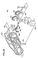
- Fig.28 is a perspective view of the hemming unit 3020
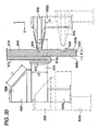
- Fig.29 is a partially sectional side view showing the hemming unit 3020 before hemming working
- Fig.30 is a partially sectional side view showing the hemming unit 3020 in hemming working.
- the outer box 3021 is illustrated perspectively by a two-dotted chain line to be able to optically recognize a structure of the hemming unit 3020.
- the hemming unit 3020 includes the hemming roller 3030 and the guide roller 3032, the support shafts 3030a and 3032a for axially supporting these, a first movable portion 3100 as a movable portion having the support shaft 3032a at an upper end face thereof, a second movable portion 3102 as a movable portion having the support shaft 3032a at an upper end face thereof, a cylinder 3106 for connecting and displacing in X direction the first movable portion 3100 and the second movable portion 3102, and a base portion 3110 for supporting the first movable portion 3100, the second movable portion 3012 and the cylinder 3106 relative to the robot 3022.
- the base portion 3110 is constituted by a shape of a substantially channel-like shape in which a lower side thereof is longer than an upper side thereof in a side view thereof (refer to Fig.29 ), and the base portion 3110 is provided with a third movable portion 3114 displaceably supported in Y direction by a second rail 3025 extended in Y direction to be supported by a support member 3022b fixed to a bracket 3022a and substantially in a channel-like shape in a side view thereof (refer to Fig.29 ) by way of a linear guide 3112, a base 3116 in a rectangular shape projected from a slightly lower portion of a center in Y direction of the third movable portion 3114, a front end support member 3118 in a rectangular shape provided at a front end face of the base 3116, a flat plate 3120a in a rectangular shape projected from an upper portion of the third movable portion 3114 in a direction in parallel with the base 3116, and a partitioning portion 3120b in a rectangular
- first supporting means 3126 and second supporting means 3127 are arranged in series between a side face 3102b of an upper portion of the second movable portion 3120 on a side of the third movable portion 3114, and a side face 3124a projected from a front end portion of an extending portion 3122 extended from the second movable portion 3120 to a side of the third movable portion 3114 in Y direction so as not to be brought into contact with the flat plate 3120a, and the partitioning portion 3120b is provided to partition therebetween.
- a first rail 3128 is extended in parallel with the base 3116 at an upper space of the base 3116 at which the third movable portion 3114 and the front end support member 3118 are opposed to each other. Further, the first movable portion 3100 and the second movable portion 3102 are supported by the first support rail 3128 displaceably in X direction respectively by way of linear guides 3100 and 3132. That is, the first movable portion 3100 and the second movable portion 3102 are supported by the base portion 3110 by way of the linear guides 3130 and 3132 or the like, and these function as a movable mechanism.
- the second movable portion 3102 is supported by the first supporting means 3126 and the second supporting means 3127 drivenly and elastically in X direction by interposing the above-described partitioning portion 3120b. That is, when the second movable portion 3102 is displaced in a direction of being separated from the first movable portion 3100, the second supporting means 3127 is contracted by the partitioning portion 3120b, and when the second movable portion 3102 is displaced in a direction of being proximate to the first movable portion 3100, the first supporting means 3126 is contracted by the partitioning portion 3120b.
- a horizontally projected portion 3022c projected in X direction from a lower end face of the support member 3022b and the base 3116 are drivenly and elastically supported by third supporting means 3138.
- third supporting means 3138 Although a pair of two pieces of the third supporting means are provided to connect end portions on both sides of the horizontally projected portion 3022c and the base 3116, one piece thereof may naturally be constituted to connect center portions in width directions of the horizontally projected portion 3022c and the base 3116.
- the third supporting means 3126, the second supporting means 3127 and the third supporting means 3138 are constructed by similar constitutions
- the first supporting means 3126 is constituted by a shaft portion 3126a and a spring 3126b installed at a surrounding of the shaft portion 3126a
- the second supporting means 3127 is constituted by a shaft portion 3127a and a spring 3127b arranged at a surrounding of the shaft portion 3127a
- the third supporting means 3138 is constituted by a shaft portion 3138a and a spring 3138b installed at a surrounding of the shaft portion 3138a.
- the respective shaft portions 3126a, 3127a, and 3128a may be constituted by hydraulic dampers or pneumatic dampers or the like.
- the first supporting means 3126 and the second supporting means 3127 are constructed by the above-described constitutions, and therefore, as described above, the second movable portion 3102 is supported at the base portion 3110 displaceably in X direction by the linear guide 3132, and drivenly and elastically supported in X direction relative to the base portion 3110 by the first supporting means 3126 and the second supporting means 3127 by way of the partitioning portion 3120b.
- the third supporting means is constructed by the above-described constitution, and therefore, the base 3116 is drivenly and elastically supported in Y direction relative to the horizontally projected portion 3022c fixed to the robot 3022 by the third supporting means.
- the second movable portion 3102 includes one side face 3102a and other side face 3102c extended in a lower direction, the other side face 3102c is provided with a first stopper 3134 as a first locking portion, and the first stopper 3134 is engageable with a second stopper 3136 provided at a front end portion of the horizontally projected portion 3122c. That is, a front end of the first stopper 3134 is constituted by a projected portion substantially in a shape of a frustrum of a circular cone, and the second stopper 3136 is constituted by a recessed portion substantially in a shape of a cone capable of inserting the front end of the first stopper 3134.
- the first stopper 3134 and the second stopper 3136 are engaged in a state in which an interval between the hemming roller 3030 and the guide roller 3032 is maximally opened by extending a rod 3104 of the cylinder 3106, that is, in a state in which the hemming roller 3030 is separated from the vehicle 3012 before hemming working or after hemming working, mentioned later.
- the first stopper 3134 and the second stopper 3136 are not engaged with each other in a state in which the interval between the hemming roller 3030 and the guide roller 3032 is narrowed by retracting the rod 3104 and the cylinder 3106 as shown by Fig.30 , that is, in a state in which the hemming roller 3030 is brought into contact with the vehicle 3012 in hemming working, mentioned later.
- the first movable portion 3100 is brought into contact with and supported by the front end support member 3138 by a press force in a direction opposed to the side of the second movable portion 3102 by the rod 3104 connected to the cylinder 3106.
- the first movable portion 3100 is held in a state of being proximate to the second movable portion 3102 by a force attracted to a side of the second movable portion 3102 by the rod 3104.
- the hemming unit 3020 according to the second exemplary embodiment is constituted as described above. Therefore, in a state in which the first stopper 3134 and the second stopper 3136 are not engaged with each other as shown by Fig.30 , the first movable portion 3100 and the second movable portion 3102 are supported by the base portion 3110 integrally and displaceably in X direction by way of the linear guides 3130 and 3132, and the displacement in X direction is drivenly and elastically supported by the first supporting means 3126 and the second supporting means 3127.
- the base portion 3116 supporting the first movable portion 3100 and the second movable portion 3102 in this way is supported by the robot 3022 displaceably in Y direction by way of the linear guide 3112, the displacement in Y direction is drivenly and elastically supported by the third supporting means 3038. Therefore, in this case, the first movable portion 3100 and the second movable portion 3102, in other words, the hemming roller 3030 and the guide roller 3032 are supported by the robot 3022 displaceably in X direction and Y direction and drivenly and elastically.
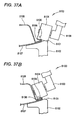
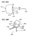
- the linear guides 3132, 3130 and 3132, the first supporting means 3126, the second supporting means 3127 and the third supporting means 3138 are operated as the floating mechanism interposed between the hemming unit 3020 and the robot 3022, and a performance of the guide roller 3032 following the first groove 3052 or the second groove 3054 in hemming working is considerably promoted, and the hemming roller 3030 can be made to follow the flange 3017 at high speed and accurately, and details thereof will be described later (refer to Fig.34 and Fig.35 ).
- the hemming roller 3030 and the guide roller 3032 are made to be proximate to position the vehicle 3012 and the moving die 3018, for example, before hemming working, by restricting the floating mechanism, the positioning can swiftly be carried out and details thereof will be described later.
- the moving die 3018 is constituted by constituting a base by a die plate 3029.
- the die plate 3049 is constituted by a plate shape, a side thereof brought into contact with the wheel arch portion 3016 is referred to as a surface 3049a (refer to Fig.32 ) and a face on an opposed side thereof is referred to as a back face 3049b to be differentiated from each other.
- a work side in view from an end portion 3016a of a wheel arch portion 3016 is referred to as an inner side, and a side opposed thereto (lower side in Fig.32 ) is referred as an outer side to be differentiated from each other.
- the die plate 3049 is constituted by a shape of a plate in an arch shape the surface 3049a of which is brought into contact with a surrounding of the wheel arch portion 3016, and the surface 3049a is set to a three-dimensional curved face in conformity with a surface of the vehicle 3012. Therefore, when the moving die 3018 is attached to the wheel arch portion 3016, the first groove 3052 and the second groove 3054 are arranged in parallel with the flange 3017, and the surface 3049a is brought into face contact with the vehicle 3012 by a wide area.
- the moving die 3018 includes an outer side circular arc portion 3050 formed along slightly on an outer side of the end portion 3016a of the wheel arch portion 3016, the first groove 3052 and the second groove 3054 provided in parallel with each other along the outer side circular arc portion 3050 at the back face 3049b, a knob 3056 provided at the back face 3049b, three clamp mechanisms 3058 provided at the surrounding, a pipe 3060 for supplying and recovering a compressed fluid to and from the clamp mechanism 3058, and a control valve 3062 for controlling to switch a fluid supply direction of the pipe 3060 or the like.
- the control valve 3062 is controlled by the controller 3024.
- the first groove 3052 is provided on an outer side of being projected from the end portion 3016a of the flange 3017 on the die plate 3049, and the second groove 3054 is provided on an inner side of the end portion 3016a.
- the moving die 3018 is small-sized since the moving die 3018 is brought into contact only with the surrounding of the wheel arch portion 3016. Further, the moving die 3018 is brought into contact with the vehicle 3012 from a side face thereof, and therefore, the moving die 3018 is not applied with a weight of the vehicle 3122, and the moving die 3018 is not constituted by a load resistant structure, and therefore, the moving die 3018 is set to be light-weighted. Therefore, the moving die 3018 is made to be movable simply and conveniently by the robot 3022 by grabbing the knob 3056 by the chuck 3034 (refer to Fig.26 and Fig.27 ).
- the clamp mechanism 3058 includes a stay 3064 extended from an end portion of the die plate 3049, a cylinder 3066 pivotably provided to the stay 3064, and an opening/closing lever 3068 inclined centering on a support shaft provided at the stay 3064.
- One end portion of the opening/closing lever 3068 constitutes a grip portion 3068a engaged with and held by a reference position of the vehicle 3012, and an end portion on an opposed side is rotatably coupled to a rod 3066a of the cylinder 3066 by way of a support shaft.
- the opening/closing lever 3068 is closed to hold the vehicle 3012 by the grip portion 3068a, and by contracting the rod 3066a, the opening/closing lever 3068 is opened (refer to a two-dotted chain line portion of Fig.31 ), and the moving die 3018 is made to be able to be proximate or separated from the vehicle 3012.
- a stop position of the vehicle 3012 on the production line 3014 is more ore less shifted from a rectified value
- the moving die 3018 is accurately positioned to the wheel arch portion 3016 by the clamp mechanism 3058.
- the outer side circular arc portion 3050 is arranged on an outer side (lower side of Fig.32 ) of the end portion 3016a of the wheel arch portion 3016.
- the first groove 3052 is slightly on an outer side of the end portion 3016a
- the second groove 3054 is on an inner side of the end portion 3016a. That is, the first groove 3052 and the second groove 3054 are arranged at positions substantially symmetrical with each other by constituting a reference by the end portion 3016a and in parallel with each other along the end portion 3016a.
- step S301 information of a vehicle kind of the vehicle 3012 carried successively is confirmed from the production control computer, thereafter, the robot 3022 returns the currently grabbed moving die 3018 to a rectified position of the storing base 3026 and grabs other moving die 3018 in correspondence with the vehicle kind by the chuck 3034.
- the hold and switch operation is not needed, further, when a plurality of pieces of the vehicles 3012 of the same vehicle kind is continuously carried, it is not naturally needed to hold and change the moving die 3018.
- step S302 the operation is at standby until the vehicle 3012 is carried by confirming a signal of the photoelectric sensor 3023.
- the vehicle 3012 is carried by the production line 3014 and is stopped at a predetermined position at a vicinity of the robot 3022.
- the operation proceeds to step S303 at a time point of confirming carrying of the vehicle 3012 by the photoelectric sensor 3023.
- the opening/closing lever 3068 of the clamp mechanism 3058 is closed by bringing the surface 3049a of the moving die 3018 into contact with the wheel arch portion 3016 of the vehicle 3012 by operating the robot 3022 and driving to switch the control valve 3062.
- the moving die 3018 is attached to the wheel arch portion 3016 and is accurately positioned to fix. That is, at step S303, the vehicle 3012 constituting a large-sized weighted object is completely stopped, and by making the small-sized and light-weighted moving die 3018 proximate thereto, positioning and fixing are carried out simply and conveniently.
- the moving die 3018 may be made to be proximate thereto while correcting a path of moving the robot 3022 while confirming a position of the moving die 3018 relative to the wheel arch portion 3016 in real time by a predetermined sensor. Further, positioning may be carried out by providing a reference pin at the moving die 3018 and inserting the reference pin into a predetermined reference hole of the vehicle 3012. Both of the positioning means may naturally be used.
- step S304 after opening the finger 3036 of the chuck 3034, the hemming unit 3020 is temporarily separated from the moving die 3018.
- the hemming unit 3020 is made to be proximate to and positioned to the outer side circular arc portion 3050 of the moving die 3018, and the guide roller 3032 is engaged with the first groove 3052.
- the first stopper 3134 and the second stopper 3136 are engaged with each other by bringing about a state of extending the rod 3014 of the cylinder 3106.
- the interval between the hemming roller 3030 and the guide roller 3032 is brought into a maximally separated state, the flange 3017 and the die plate 3049 is made to be able to be easily inserted to the separated portion, further, by maintaining a state of restricting the floating operation at the hemming unit 302, the hemming roller 3030 and the guide roller 3032 are positioned in a state of being integrally fixed to the robot 3022 without bringing about rocking or rattling.
- the hemming working apparatus 3010 of the embodiment achieves a simple and excellent positioning function of sufficiently separating the interval between the hemming roller 3030 and the guide roller 3032 by only extending the rod 3104 of the cylinder 3016 and preventing rocking or rattling of the hemming unit 3020 including the hemming roller 3030 and the guide roller 3032 by restricting the floating mechanism simultaneously.
- step S304 similar to step S305, the floating operation of the hemming unit 3020 may be restricted, in this case, there can be restrained occurrence of noise sound or vibration at the front end portion of the robot 3022 caused by rocking or rattling of the hemming unit 3020 in an operation of moving the robot 3022.
- step S306 the rod 3014 of the cylinder 3106 is contracted, the guide roller 3032 and the hemming roller 3030 are made to be proximate to each other, and as shown by Fig.32 , the moving die 3018 is pinched by the guide roller 3032 and the circular cylinder roller 3040.
- the flange 3017 is pressed by the taper roller 3038 and is inclined to bend by 45° along the conical face.
- a distance between the guide roller 3032 and the circular cylinder roller 3040 is rectified by a width w between a bottom portion of the first groove 3052 and the surface 3049a and the guide roller 3032 and the circular cylinder roller 3040 are not made to be excessively proximate to each other. Therefore, the flange 3017 is not bent by a rectified amount or more or is not constituted by a wavy shape. Further, the moving die 3018 can firmly be pinched by arranging the guide roller 3032 and the circular cylinder roller 3040 such that positions thereof in Y direction coincide with each other. Thereby, the moving die 3018 is not applied with a moment force and an elastic deformation or a shift can be prevented from being brought about.
- the engagement between the first stopper 3134 and the second stopper 3136 is disengaged and the restriction of the floating mechanism is released at the hemming unit 3020. That is, according to the hemming working apparatus 3010 of the second exemplary embodiment, by a simple operation of retracting the rod 3014 of the cylinder 3106, the operation of pressing the flange 3017 is carried out by the taper roller 3038, further, also the restriction of the floating mechanism is released to be able to prepare for hemming working explained in the following steps.
- a first hemming step of inclining to bend the flange 3017 by 45° in an inner side direction is continuously carried out. That is, there is carried out a first hemming step of rolling the hemming roller 3030 and the guide roller 3032 while rotating the hemming roller 3030 and the guide roller 3032 in directions reverse to each other in a state of maintaining a press force and a distance therebetween to predetermined values and continuously bending the flange 3017 by a conical face of the taper roller 3038.
- the hemming roller 3030 and the guide roller 3032 are supported by the floating mechanism as described above, and therefore, the hemming roller 3030 and the guide roller 3032 can be displaced in X direction and Y direction while maintaining positions thereof relative to each other, and even when more or less error is present in a locus of operating the robot 3022, the guide roller 3032 can be moved by accurately following the first groove 3052, and therefore, a speed of rolling the hemming roller 3030 and the guide roller 3032 can be constituted by a high speed.
- the taper roller 3038 can press and deform the flange 3017 in a rectified direction. Further, an accuracy of operating the robot 3022 is not needed to be an extremely high accuracy, and high speed formation of the operating speed and simplification of control procedure are achieved. Hemming working by the first hemming step is carried out over an entire length of the flange 3017.
- step S308 as shown by a two-dotted chain line portion of Fig.35 , the rod 3104 of the cylinder 3106 is more or less extended, and a distance between the hemming roller 3030 and the guide roller 3032 is slightly prolonged to be separated from the vehicle 3012 and the moving die 3018.
- the rod 3104 is extended more or less as described above in consideration that the distance of moving the hemming unit 3020 at the following step S309 is comparatively short or the like.
- the hemming roller 3030 and the guide roller 3032 are moved in an arrow mark Y1 direction by moving the hemming unit 3020.
- the moving distance is equal to a distance between the first groove 3052 and the second groove 3054.
- the guide roller 3032 is engaged with the second groove 3054 by retracting the rod 3104 of the cylinder 3106. Further, the guide roller 3032 and the hemming roller 3030 are made to be proximate to each other, and as shown by Fig.35 , the moving die 3018 is pressed to pinch by the guide roller 3032 and the circular cylinder roller 3040. In this way, the operating procedure in moving the guide roller 3032 from the first groove 3052 to the second groove 3054 is simple and the guide roller 3032 is only moved in the arrow mark Y1 direction while making the direction of the hemming unit 3020 constant. Further, also the moving distance is comparatively short, and therefore, the shifting is finished in a short period of time.
- the flange 3017 is pressed by the circular cylinder roller 3040 and is bent to be brought into contact with the back face of the wheel arch portion 3016. That is, the flange 3017 is further bent by 45° from the first hemming step, that is, by 90° from an initial angle.
- step S311 by rolling the guide roller 3032 while engaging the guide roller 3032 with the second groove 3054, a second hemming step of folding to bend the flange 3017 to be brought into contact with the back face of the wheel arch portion 3016 is continuously carried out. That is, the second hemming step is carried out by continuously bending the flange 3017 by an outer peripheral circular cylinder face of the circular cylinder roller 3040 by rolling the hemming roller 3030 and the guide roller 3032 in directions reverse to each other in a state of maintaining a press force or a distance between the hemming roller 3030 and the guide roller 3032 to predetermined values.
- the second groove 3054 is provided on the side of the back face 3049b of the die plate 3049, and therefore, the flange 3017 and the die plate 3049 are firmly pressed by being pinched by the circular cylinder roller 3040 and the guide roller 3032, further, a press force is not dispersed to other portion and there is not a stopper of restricting the press force and the press force is concentratedly operated to the flange 3017. Thereby, the flange 3017 is firmly bent.
- the hemming roller 3030 and the guide roller 3032 are moved on an accurate path along the second groove 3054 by the operation of the floating mechanism and the working is carried out over the entire length of the flange 3017.
- step S312 similar to step S308, the rod 3104 of the cylinder 3106 is retracted, and the distance between the hemming roller 3030 and the guide roller 3032 is slightly prolonged to be separated from the moving die 3018. Further, the hemming unit 3020 is temporarily separated from the moving die 3018.
- a processing of opening the moving die 3018 is carried out. That is, after changing the direction of the hemming unit 3020, the hemming unit is made to be proximate to the back face 3049b, the knob 3056 is grabbed by the chuck 3034, further, the opening/closing lever 3068 of the clamp mechanism 3058 is opened by driving to switch the control valve 3062.
- a standby processing is carried out at step S314. That is, the moving die 3018 is separated from the vehicle 3012 by moving the robot 3022 to a predetermined standby position.
- the controller 3024 informs that the hemming working has normally been finished to the production control computer.
- the informed production control computer confirms that a condition is established for other requirement and drives the production line 3014 and carry the vehicle 3012 finished with the hemming working to a next step.
- the hemming unit 3020 including the hemming roller 3030 and the guide roller 3032 is supported by the robot 3022 displaceably in X direction constituting the direction of aligning the support shaft 3030a and the support shaft 3032a and in Y direction constituting the axial directions of the support shaft 3030a and the support shaft 3032a by way of the floating mechanism constituted by the linear guides 3112, 3130 and 3132, the first supporting means 3126, the second supporting means 3127 and the third supporting means 3138, and therefore, a performance of the guide rollers 3032 of following the first groove 3052 and the second groove 3054 in hemming working is significantly promoted, the hemming roller 3030 is made to be able to accurately follow the flange 3017, and a drawback that the guide roller 3032 rides over the first groove 3052 or the second groove 3054 can be avoided.
- the guide roller 3032 can be moved by accurately following the first groove 3052. Therefore, the speed of rolling the hemming roller 3030 and the guide roller 3032 can be constituted by a high speed, and a time period of an operation required for hemming working can be shortened.
- the hemming working apparatus 3010 includes the first stopper 3134 and the second stopper 3136 constituting the restricting means for restricting the floating mechanism, and therefore, the operation of the floating mechanism can be restricted in accordance with respective operation steps. Therefore, by restricting the operation of the floating mechanism in positioning the hemming roller 3030 and the guide roller 3032, the hemming roller 3030 and the guide roller 3032 can accurately and swiftly be positioned in a state of being integrally fixed to the robot 3022 without bringing about rocking or rattling.
- use or restriction of the floating mechanism in accordance with the respective operation steps can be selected integrally with an operation of extracting or an operation of retracting the rod 3014 of the cylinder 3106 of making the hemming roller 3030 and the guide roller 3032 proximate to each other and remote from each other. That is, in positioning the hemming roller 3030 and the guide roller 3032, by extending the rod 3104 for separating the hemming roller 3030 and the guide roller 3032, the first stopper 3134 and the second stopper 3136 are engaged and the floating mechanism is restricted.
- hemming working apparatus 3010 by using the small-sized and light weighted moving die 3018, hemming working can be carried out by bringing the moving die 3018 into contact with the vehicle 3012 carried on the production line 3014, and an exclusive space for hemming working is not needed. Further, hemming working is carried out in the production line 3014 similar to other assembling and working step, and therefore, a productivity is promoted by dispensing with time and labor of carrying the vehicle 3012 to other exclusive space only for the hemming working.
- the hemming working apparatus 3010 working is carried out while bringing the moving die 3018 into contact with a working portion of the work, and therefore, the hemming working apparatus 3010 is applied regardless of the size of the work.
- the moving die 3018 is small-sized and light-weighted, and therefore, a plurality of pieces of the moving dies can be stored to the storing base 3026, storing and control thereof is simple and convenient, the robot 3022 can carry out hemming working by selecting the moving die 3018 in accordance with the vehicle kind, and a general purpose performance is promoted.
- the hemming roller 3030 can be used both in the first roll hemming and the second roll hemming, and therefore, interchange of the roller is not needed.
- the first groove 3052 and the second groove 3054 are provided on the side of the back face 3049b, and therefore, in the second hemming step, the flange 3017 and the die plate 3049 can be pinched to press by the circular cylinder roller 3040 and the guide roller 3032.
- one piece of the robot 3022 can be made to serve as the moving means of the moving die 3018 and the working means of the hemming working.
- the invention is not limited to the above-described embodiment but can naturally adopt various constitutions without deviating from the gist of the invention.
- the operation of engaging the first stopper 3134 and the second stopper 3136 as means for restricting the floating mechanism is operated integrally with operations of making the hemming roller 3030 and the guide roller 3032 proximate to each other and remote from each other
- the invention is not limited thereto but the restricting means may be constituted to operate separately from the operations of making the hemming roller 3030 and the guide roller 3032 proximate to each other and remote from each other to be controlled by the controller 3024 or the like.
- first groove 3052 and the second groove 3054 are not necessarily limited to the groove shape so far as the guide roller 3032 is guided thereby, for example, a peripheral face of the guide roller 3032 may be provided with a ring-groove by constituting a projected rail (guide streak).
- the floating mechanism is applicable also to other than the hemming working apparatus using the guide roller 3032 as in the embodiment, for example, an apparatus of omitting the guide roller 3032 may be constructed by a constitution in which an upper end face of the second movable portion 3012 is arranged with the hemming roller 3030, the front end support member 3138 is extended to a lower side, and the rod 3104 of the cylinder 3106 is fixed to the front end support member 3118.
- the floating mechanism can naturally be provided to operate to only either one of the side of the guide roller 3032 or the side of the hemming roller 3030 in accordance with a condition of using the hemming working apparatus or the like.
- the invention is not limited thereto but is naturally applicable to other portion by setting a corresponding moving die thereto.
- a hem portion of a front wheel house, a hem portion of a door, a hem portion of a bonnet and a hem portion of a trunk and the like in the vehicle 3012 can be pointed out.
- roll hemming is not limited to a case of folding to bend one sheet of a thin plate but, for example, an end portion of an inner panel constituting a thin plate provided separately may be pinched by folding to bend the flange 3017.
Landscapes
- Engineering & Computer Science (AREA)
- Mechanical Engineering (AREA)
- Robotics (AREA)
- Bending Of Plates, Rods, And Pipes (AREA)
- Processing Of Meat And Fish (AREA)
- Punching Or Piercing (AREA)
- Finish Polishing, Edge Sharpening, And Grinding By Specific Grinding Devices (AREA)
- Soil Working Implements (AREA)
- Forging (AREA)
- Straightening Metal Sheet-Like Bodies (AREA)
Claims (2)
- Bördel-Bearbeitungsverfahren, ein Werkstück (16) durch eine Form (18) und eine Rolle (30) einzuklemmen und einen an einem Endabschnitt des Werkstücks (16) vorgesehenen Flansch einer Bördel-Bearbeitung zu unterziehen,
dadurch gekennzeichnet, dass die Form (18) elastisch an das Werkstück (16) gedrückt wird, wobei ein elastisches Element (58) zwischen der Form (18) und dem Werkstück (16) vorgesehen ist, so dass die Form (18) an einem Abschnitt in Kontakt mit dem Werkstück (16) gebracht werden kann, an dem auf das Werkstück (16) Druck durch die Rolle (30) ausgeübt wird, und
dass die Form (18) außer an dem Bearbeitungsabschnitt (52a) des Werkstücks (16) von dem Werkstück (16) getrennt sein kann. - Bördel-Bearbeitungsvorrichtung, umfassend:eine Form (18) und eine Rolle (30), um ein Werkstück (16) einzuklemmen und einen an einem Endabschnitt des Werkstücks (16) vorgesehen Flansch einer Bördel-Bearbeitung zu unterziehen,gekennzeichnet durch ein elastisches Element (58), das im Betrieb zwischen der Form (18) und dem Werkstück (16) vorgesehen ist, und das in eine Druck-Richtung der Rolle (30) elongierbar und kontrahierbar ist.
Applications Claiming Priority (10)
| Application Number | Priority Date | Filing Date | Title |
|---|---|---|---|
| JP2005350884A JP4523542B2 (ja) | 2005-12-05 | 2005-12-05 | ヘミング加工方法及び加工装置 |
| JP2005350619A JP4617249B2 (ja) | 2005-12-05 | 2005-12-05 | ヘミング加工方法及びヘミング加工装置 |
| JP2005350615A JP4562648B2 (ja) | 2005-12-05 | 2005-12-05 | ヘミング加工装置 |
| JP2005350821A JP4469784B2 (ja) | 2005-12-05 | 2005-12-05 | ヘミング加工方法及び加工装置 |
| JP2005350809A JP4690875B2 (ja) | 2005-12-05 | 2005-12-05 | ヘミング加工方法及び加工装置 |
| JP2006051234A JP4559374B2 (ja) | 2006-02-27 | 2006-02-27 | ローラヘミング装置及びローラヘミング加工方法 |
| JP2006066738A JP4865370B2 (ja) | 2006-03-10 | 2006-03-10 | ロールヘミング方法及び溶接構造物 |
| JP2006187582A JP5033368B2 (ja) | 2006-07-07 | 2006-07-07 | ローラヘミング装置 |
| JP2006202039A JP5027459B2 (ja) | 2006-07-25 | 2006-07-25 | ヘミング加工方法及びヘミング加工装置 |
| EP06834042A EP1958714B1 (de) | 2005-12-05 | 2006-12-05 | Umbördelverfahren und umbördelvorrichtung |
Related Parent Applications (2)
| Application Number | Title | Priority Date | Filing Date |
|---|---|---|---|
| EP06834042A Division EP1958714B1 (de) | 2005-12-05 | 2006-12-05 | Umbördelverfahren und umbördelvorrichtung |
| EP06834042.1 Division | 2006-12-05 |
Publications (3)
| Publication Number | Publication Date |
|---|---|
| EP2110190A2 EP2110190A2 (de) | 2009-10-21 |
| EP2110190A3 EP2110190A3 (de) | 2010-04-07 |
| EP2110190B1 true EP2110190B1 (de) | 2011-02-23 |
Family
ID=38122816
Family Applications (5)
| Application Number | Title | Priority Date | Filing Date |
|---|---|---|---|
| EP09165975A Not-in-force EP2108466B1 (de) | 2005-12-05 | 2006-12-05 | Umbördelverfahren und Umbördelvorrichtung |
| EP06834042A Not-in-force EP1958714B1 (de) | 2005-12-05 | 2006-12-05 | Umbördelverfahren und umbördelvorrichtung |
| EP09165982A Ceased EP2116318B1 (de) | 2005-12-05 | 2006-12-05 | Umbördelvorrichtung |
| EP09165980A Withdrawn EP2108468A3 (de) | 2005-12-05 | 2006-12-05 | Umbördelverfahren und Umbördelvorrichtung |
| EP09165977A Ceased EP2110190B1 (de) | 2005-12-05 | 2006-12-05 | Umbördelverfahren und Umbördelvorrichtung |
Family Applications Before (4)
| Application Number | Title | Priority Date | Filing Date |
|---|---|---|---|
| EP09165975A Not-in-force EP2108466B1 (de) | 2005-12-05 | 2006-12-05 | Umbördelverfahren und Umbördelvorrichtung |
| EP06834042A Not-in-force EP1958714B1 (de) | 2005-12-05 | 2006-12-05 | Umbördelverfahren und umbördelvorrichtung |
| EP09165982A Ceased EP2116318B1 (de) | 2005-12-05 | 2006-12-05 | Umbördelvorrichtung |
| EP09165980A Withdrawn EP2108468A3 (de) | 2005-12-05 | 2006-12-05 | Umbördelverfahren und Umbördelvorrichtung |
Country Status (6)
| Country | Link |
|---|---|
| US (2) | US8272243B2 (de) |
| EP (5) | EP2108466B1 (de) |
| CN (6) | CN101817042B (de) |
| CA (1) | CA2632539C (de) |
| DE (2) | DE602006020362D1 (de) |
| WO (1) | WO2007066670A1 (de) |
Cited By (1)
| Publication number | Priority date | Publication date | Assignee | Title |
|---|---|---|---|---|
| CN107442627A (zh) * | 2017-08-04 | 2017-12-08 | 芜湖瑞德机械科技有限公司 | 高效弯弧翻边器及其使用方法 |
Families Citing this family (50)
| Publication number | Priority date | Publication date | Assignee | Title |
|---|---|---|---|---|
| EP2108466B1 (de) * | 2005-12-05 | 2013-03-20 | Honda Motor Co., Ltd. | Umbördelverfahren und Umbördelvorrichtung |
| DE102007002856B4 (de) * | 2007-01-15 | 2012-02-09 | Edag Gmbh & Co. Kgaa | Vorrichtung zum Bördeln und Schweißen oder Löten von Bauteilen |
| JP5101901B2 (ja) * | 2007-02-07 | 2012-12-19 | 本田技研工業株式会社 | ヘミング加工方法及びヘミング加工装置 |
| US20100281940A1 (en) * | 2009-03-12 | 2010-11-11 | Harrow Aaron E | Vertical air compliant hemming head |
| JP5399135B2 (ja) * | 2009-06-09 | 2014-01-29 | トヨタ自動車株式会社 | ヘミング加工装置 |
| JP5215946B2 (ja) * | 2009-06-12 | 2013-06-19 | 本田技研工業株式会社 | ローラヘミング装置およびローラヘミング方法 |
| KR101163696B1 (ko) * | 2009-12-03 | 2012-07-09 | 기아자동차주식회사 | 차량의 휠 하우스용 헤밍장치 |
| WO2012127581A1 (ja) * | 2011-03-18 | 2012-09-27 | トヨタ自動車株式会社 | 車両用ホイールハウス部構造 |
| CN103252423B (zh) * | 2012-02-16 | 2015-07-22 | 北京环都人工环境科技有限公司 | 滚边机 |
| EP2853358A1 (de) * | 2012-05-21 | 2015-04-01 | Kabushiki Kaisha Yaskawa Denki | Roboter und robotersystem |
| CN103302154B (zh) * | 2012-10-26 | 2016-07-20 | 青岛嘉龙自动化设备有限公司 | 金属板料滚边装置及其方法 |
| US9547416B2 (en) | 2012-11-14 | 2017-01-17 | Facebook, Inc. | Image presentation |
| US20140196516A1 (en) * | 2013-01-17 | 2014-07-17 | Hirotec America, Inc. | Rotary wheelhouse roller hemming assembly |
| US8820822B2 (en) * | 2013-02-07 | 2014-09-02 | GM Global Technology Operations LLC | Wheel house liner with hemmed edge, and system and method of manufacturing thereof |
| JP6300066B2 (ja) * | 2013-11-28 | 2018-03-28 | スズキ株式会社 | パネル部品の接合方法 |
| US10835948B2 (en) | 2014-07-09 | 2020-11-17 | The Boeing Company | Adjustable retaining structure for a cradle fixture |
| US10435940B2 (en) * | 2014-09-11 | 2019-10-08 | Republic Doors and Frames | Welded steel door |
| JP6360027B2 (ja) * | 2014-11-14 | 2018-07-18 | フェルロボティクス コンプライアント ロボット テクノロジー ゲーエムベーハーFerrobotics Compliant Robot Technology GmbH | ロボットローラヘミングの装置と方法 |
| US10144048B2 (en) * | 2014-11-19 | 2018-12-04 | Ford Global Technologies, Llc | High stiffness and high access forming tool for incremental sheet forming |
| DE202014105862U1 (de) * | 2014-12-04 | 2016-03-03 | Kuka Systems Gmbh | Falzwerkzeug und Falzeinrichtung |
| DE102015100659B4 (de) | 2015-01-19 | 2023-01-05 | Fft Produktionssysteme Gmbh & Co. Kg | Bördelsystem, Bördeleinheit und Bördelverfahren für ein autarkes Bördeln |
| CN104785598B (zh) * | 2015-04-27 | 2017-04-19 | 安徽鲲鹏装备模具制造有限公司 | 一种辊轧折边机 |
| JP6520478B2 (ja) * | 2015-06-30 | 2019-05-29 | 株式会社デンソーウェーブ | ロボットアームの操作システム |
| US10220515B2 (en) * | 2015-11-30 | 2019-03-05 | Seiko Epson Corporation | Robot and control method for robot |
| DE102015223921A1 (de) * | 2015-12-01 | 2017-06-01 | Siemens Healthcare Gmbh | Verfahren zum Betreiben eines medizinisch-robotischen Geräts sowie medizinisch-robotisches Gerät |
| DE102016211571A1 (de) * | 2016-06-28 | 2017-12-28 | Audi Ag | Rollfalzvorrichtung und Verfahren zum Falzen eines Kantenbereichs eines Blechteils |
| JP6512665B2 (ja) * | 2016-11-04 | 2019-05-15 | 株式会社Subaru | ローラヘミング装置、及びローラヘミング方法 |
| CN106617441B (zh) * | 2016-11-15 | 2018-04-03 | 中山市理创机械设备有限公司 | 一种布料粘合机 |
| CN106523493B (zh) * | 2016-11-15 | 2019-03-05 | 大同新成新材料股份有限公司 | 一种受电弓滑板包边机 |
| CN107008820B (zh) * | 2017-05-11 | 2019-03-29 | 无锡市光彩机械制造有限公司 | 一种提升筒全自动生产线 |
| CN107186493A (zh) * | 2017-07-24 | 2017-09-22 | 西莱特电梯(中国)有限公司 | 电梯门套生产线 |
| JP6502432B2 (ja) * | 2017-08-17 | 2019-04-17 | 孝久 三浦 | ダイならびにローラーヘミング加工システムおよび金属ワークにローラーヘミング加工を施す方法 |
| CN107931453B (zh) * | 2017-11-24 | 2023-10-17 | 安徽鲲鹏装备模具制造有限公司 | 一种冷柜内胆的底板预铆接设备 |
| CN110465570B (zh) * | 2018-05-11 | 2022-11-25 | 富泰华工业(深圳)有限公司 | 滚压机构 |
| CN108637060B (zh) * | 2018-05-30 | 2019-09-24 | 芜湖同创模具机械有限公司 | 一种刹车片用弧形钢背板加工装置 |
| AU2019346637B2 (en) * | 2018-09-27 | 2023-12-21 | Inno-Spin LLC | Multi-axis roll-forming methods, systems, and products |
| DE102018132090A1 (de) * | 2018-11-13 | 2020-05-14 | Magna International Inc. | Verfahren und Vorrichtung zum Verformen von Materialien mit geringer Verformbarkeit |
| KR20200068802A (ko) * | 2018-12-05 | 2020-06-16 | 현대자동차주식회사 | 패널 헤밍장치 및 이를 이용하여 헤밍하는 방법 |
| CN109702018B (zh) * | 2019-02-22 | 2023-08-25 | 江苏劲嘉新型包装材料有限公司 | 可调式压辊装置 |
| JP7294869B2 (ja) * | 2019-04-25 | 2023-06-20 | 株式会社Subaru | ローラヘム加工装置及び該装置を用いた予備曲げ加工方法 |
| CN110014635B (zh) * | 2019-05-17 | 2021-08-03 | 东莞市贸隆机械制造有限公司 | 板材折边机 |
| US20220347794A1 (en) * | 2019-07-12 | 2022-11-03 | Honda Motor Co., Ltd. | Semi-finished product for joined product, and method for manufacturing joined product employing same |
| CN110328266B (zh) * | 2019-08-16 | 2024-04-09 | 江苏三迪机车制造有限公司 | 折边组件及折边方法 |
| CN111687264B (zh) * | 2020-06-19 | 2022-04-22 | 中国科学院工程热物理研究所 | 一种用于托板螺帽的扇形托板的制备装置及方法 |
| TWI762025B (zh) * | 2020-11-10 | 2022-04-21 | 財團法人工業技術研究院 | 鈑件摺邊裝置 |
| CN112775343A (zh) * | 2021-01-21 | 2021-05-11 | 天永机械电子(太仓)有限公司 | 一种顶盖天窗滚边设备 |
| JP2023094786A (ja) * | 2021-12-24 | 2023-07-06 | 川崎重工業株式会社 | ロボット制御装置、ロボットシステム、ロボット制御プログラム |
| CN118067169B (zh) * | 2024-04-17 | 2024-07-23 | 洛阳石化工程建设集团有限责任公司 | 环境状态变化量记录仪器的收纳支撑装置及其使用方法 |
| US12508641B1 (en) * | 2024-11-26 | 2025-12-30 | Fca Us Llc | Hemming apparatus |
| CN120115574B (zh) * | 2025-05-14 | 2025-08-12 | 四川福摩斯工业技术有限公司 | 一种用于汽车车门的机器人滚边设备 |
Family Cites Families (76)
| Publication number | Priority date | Publication date | Assignee | Title |
|---|---|---|---|---|
| US3680346A (en) * | 1971-01-04 | 1972-08-01 | Rudolph R Wilcox | Crimping tool |
| US3875692A (en) * | 1973-12-17 | 1975-04-08 | Sylvan S Teel | Quick change number indicator |
| US3889618A (en) * | 1974-06-26 | 1975-06-17 | Clark Equipment Co | Rolling apparatus |
| US4021909A (en) * | 1976-02-13 | 1977-05-10 | Dayco Corporation | Hand portable device for fastening a holding bar on a printing blanket and method of fastening same |
| JP2579530B2 (ja) | 1988-06-24 | 1997-02-05 | マツダ株式会社 | ヘミング成形方法 |
| JP2675347B2 (ja) * | 1988-09-06 | 1997-11-12 | マツダ株式会社 | ヘミング成形装置 |
| JPH0829360B2 (ja) * | 1989-08-15 | 1996-03-27 | 日産自動車株式会社 | ロールヘム加工装置 |
| JPH03258428A (ja) * | 1990-03-07 | 1991-11-18 | Toyota Motor Corp | ヘミング加工部ずれ防止方法 |
| JPH04157028A (ja) | 1990-10-15 | 1992-05-29 | Nissan Motor Co Ltd | ヘミング加工装置 |
| JPH04253524A (ja) * | 1991-01-29 | 1992-09-09 | Mitsubishi Motors Corp | ヘミング加工方法及びそれに用いるヘミング加工用工具 |
| JPH0790299B2 (ja) | 1991-08-01 | 1995-10-04 | トライエンジニアリング株式会社 | ローラー式ヘミング加工方法 |
| JPH0578327A (ja) | 1991-09-18 | 1993-03-30 | Hokuriku Seiyaku Co Ltd | ジベンゾシクロヘプタピリジン誘導体 |
| JP2561596Y2 (ja) * | 1992-04-03 | 1998-01-28 | 関東自動車工業株式会社 | ヘミング装置 |
| JP2579530Y2 (ja) | 1992-04-06 | 1998-08-27 | 日本電信電話株式会社 | 自走式地震探査起震装置 |
| JP2561596B2 (ja) | 1992-06-08 | 1996-12-11 | 三洋化成工業株式会社 | 樹脂用改質剤 |
| EP0577876B1 (de) * | 1992-07-09 | 1996-09-04 | TRIENGINEERING Co., Ltd. | Vorrichtung zum Verbinden eines Werkstücks |
| JP3258428B2 (ja) | 1993-04-02 | 2002-02-18 | 日本インター株式会社 | 複合半導体装置の製造方法 |
| JPH06297046A (ja) | 1993-04-16 | 1994-10-25 | Torai Eng Kk | ヘミング加工方法およびヘミング加工装置 |
| JP2924569B2 (ja) | 1993-06-03 | 1999-07-26 | 日産自動車株式会社 | ヘミング装置 |
| JPH0760370A (ja) | 1993-08-04 | 1995-03-07 | Taiho Seiki Co Ltd | ヘミング加工装置 |
| JPH0768324A (ja) | 1993-08-31 | 1995-03-14 | Taiho Seiki Co Ltd | ヘミング加工装置 |
| JPH07132327A (ja) | 1993-09-14 | 1995-05-23 | Toyota Motor Corp | ローラヘミング装置 |
| JPH0790299A (ja) | 1993-09-24 | 1995-04-04 | Fudo Kagaku:Kk | 洗濯用ペースト状カリ石鹸 |
| JPH07227677A (ja) * | 1994-02-21 | 1995-08-29 | Kanto Auto Works Ltd | スポット溶接装置 |
| NL9400927A (nl) * | 1994-06-08 | 1996-01-02 | Johan Massee | Werkwijze en inrichting voor het vormen van een rand aan een lampreflector. |
| US5623805A (en) * | 1995-04-20 | 1997-04-29 | M.I.C. Industries, Inc. | Seaming device capable of seaming curved and straight panels |
| DE29606725U1 (de) | 1996-04-16 | 1996-08-14 | Trumpf Gmbh & Co, 71254 Ditzingen | Maschine zum Umbiegen eines Blechrandes |
| JP3824777B2 (ja) * | 1998-04-30 | 2006-09-20 | 関東自動車工業株式会社 | ローラヘミング装置 |
| EP1097759A4 (de) * | 1998-09-08 | 2003-07-23 | Tri Engineering Company Ltd | Rollenbearbeitungsvorrichtung und verfahren |
| SE513776C2 (sv) * | 1999-03-18 | 2000-11-06 | Abb Ab | Falsningsverktyg, förfarande för dess framställning samt användning av detta verktyg |
| SE514087C2 (sv) | 1999-04-19 | 2000-12-18 | Abb Ab | Förfarande vid sammanfogning |
| JP3669259B2 (ja) | 2000-09-28 | 2005-07-06 | トヨタ車体株式会社 | ロールヘミング加工方法及びそれに用いるロールヘミング装置 |
| JP3642020B2 (ja) * | 2000-11-09 | 2005-04-27 | トヨタ車体株式会社 | ロールヘミング加工方法 |
| AU2001218764A1 (en) * | 2000-12-15 | 2002-06-24 | Spiro S.A. | Folded-seam connection, method of producing it and device |
| DE10111374B4 (de) * | 2001-03-09 | 2005-02-03 | Audi Ag | Bördelvorrichtung zum Umlegen einer Bördelkante eines Werkstücks durch Rollfalzen |
| US6439371B1 (en) * | 2001-03-14 | 2002-08-27 | Valiant Corporation | Workpiece loader/unloader system |
| JP2002349564A (ja) * | 2001-05-31 | 2002-12-04 | Thk Co Ltd | 直線案内装置の軌道レール取付構造 |
| JP2003103325A (ja) * | 2001-09-26 | 2003-04-08 | Nissan Motor Co Ltd | ロールヘム加工装置およびロールヘム加工方法 |
| JP3623474B2 (ja) * | 2001-10-31 | 2005-02-23 | トライエンジニアリング株式会社 | ヘミング加工装置およびヘミング加工方法 |
| JP2004050265A (ja) * | 2002-07-23 | 2004-02-19 | Ito Takashi | 金型 |
| FR2843549B1 (fr) | 2002-08-13 | 2005-05-27 | Process Conception Ing Sa | Procede et dispositif d'assemblage de pieces par sertissage d'un bord peripherique |
| EP1447155B1 (de) * | 2003-01-20 | 2005-05-04 | COMAU SpA | Rollbördelwerkzeug und Bördelverfahren |
| JP2005014069A (ja) | 2003-06-27 | 2005-01-20 | Torai Engineering Kk | ローラ式曲げ加工装置およびその加工方法 |
| CN1222377C (zh) | 2003-09-04 | 2005-10-12 | 卢惠林 | 工字轮卷边成型工艺 |
| ITTO20030726A1 (it) * | 2003-09-23 | 2005-03-24 | Comau Spa | Procedimento ed impianto per la graffatura di pezzi di lamiera |
| JP4157028B2 (ja) | 2003-12-26 | 2008-09-24 | 有限会社クスベ産業 | 法面緑化工法 |
| US20050217339A1 (en) * | 2004-03-30 | 2005-10-06 | Tesco Engineering Inc. | Roller type hemming apparatus |
| US7152447B2 (en) * | 2004-03-30 | 2006-12-26 | Tesco Engineering, Inc. | Roller type hemming apparatus |
| DE102004016385B3 (de) * | 2004-04-02 | 2005-09-08 | Audi Ag | Rollfalzvorrichtung zum Verbinden der Plattenränder zweier Blechplatten mittels eines Falzrandes |
| JP4943666B2 (ja) | 2004-05-11 | 2012-05-30 | 本田技研工業株式会社 | ロールヘミング加工方法及び加工装置 |
| JP2005333756A (ja) * | 2004-05-21 | 2005-12-02 | Alps Electric Co Ltd | 静電吸引駆動装置 |
| US20050262912A1 (en) * | 2004-05-25 | 2005-12-01 | Tesco Engineering, Inc. | Robotic roller hemming alignment apparatus and method |
| US7290423B2 (en) * | 2004-06-28 | 2007-11-06 | Gm Global Technology Operations, Inc. | Roller hemming apparatus and method |
| DE202004012580U1 (de) * | 2004-08-10 | 2005-09-22 | Kuka Schweissanlagen Gmbh | Falzwerkzeug zum Roboterfalzen |
| DE202005005880U1 (de) * | 2005-04-13 | 2005-09-29 | Edag Engineering + Design Ag | Bördelvorrichtung mit Werkstückschutz |
| DE502005001712D1 (de) * | 2004-09-24 | 2007-11-29 | Edag Eng & Design Ag | Bördelvorrichtung und Bördelverfahren mit Bauteilschutz |
| US20060225631A1 (en) * | 2005-04-08 | 2006-10-12 | Tesco Engineering Inc. | Roller type hemming apparatus |
| GB2439693B (en) * | 2005-04-27 | 2010-07-07 | Honda Motor Co Ltd | Roll hemming method and roll hemming apparatus |
| JP4870479B2 (ja) * | 2005-06-21 | 2012-02-08 | 本田技研工業株式会社 | ヘミング加工方法及びヘミング加工装置 |
| JP4939774B2 (ja) * | 2005-06-22 | 2012-05-30 | 本田技研工業株式会社 | ローラヘミング装置及びローラヘミング方法 |
| US7204116B2 (en) * | 2005-07-05 | 2007-04-17 | Tesco Engineering, Inc. | Flanging apparatus for roller hemming |
| EP2108466B1 (de) * | 2005-12-05 | 2013-03-20 | Honda Motor Co., Ltd. | Umbördelverfahren und Umbördelvorrichtung |
| DE102006028833A1 (de) * | 2006-06-21 | 2007-12-27 | Thyssenkrupp Drauz Nothelfer Gmbh | Verfahren zum Falzen eines Randes eines Blechbauteils, insbesondere eines Blechbauteils einer Kfz.-Karosserie |
| JP5101901B2 (ja) * | 2007-02-07 | 2012-12-19 | 本田技研工業株式会社 | ヘミング加工方法及びヘミング加工装置 |
| JP5111911B2 (ja) * | 2007-03-23 | 2013-01-09 | 本田技研工業株式会社 | ヘミング加工方法及びパネルアセンブリ製造方法 |
| US20080236236A1 (en) * | 2007-03-30 | 2008-10-02 | Hirotec America, Inc. | Wheelhouse robotic roller hemming |
| JP5118384B2 (ja) * | 2007-04-19 | 2013-01-16 | 本田技研工業株式会社 | ヘミング加工方法 |
| US20090083962A1 (en) * | 2007-09-27 | 2009-04-02 | Langdon Incorporated | Flange-forming system for tube and related methods |
| US20090235712A1 (en) * | 2008-03-24 | 2009-09-24 | Hirotec America, Inc. | Integrated push pull roller head |
| US20090235505A1 (en) * | 2008-03-24 | 2009-09-24 | Hirotec America, Inc. | Hem flange control roller |
| US20090235713A1 (en) * | 2008-03-24 | 2009-09-24 | Hirotec America, Inc. | Magnetically actuated roller head |
| JP5215946B2 (ja) * | 2009-06-12 | 2013-06-19 | 本田技研工業株式会社 | ローラヘミング装置およびローラヘミング方法 |
| JP4795462B2 (ja) * | 2009-11-12 | 2011-10-19 | ファナック株式会社 | 力センサを搭載したロボットマニピュレータを用いたロールヘム加工装置 |
| JP2011131255A (ja) * | 2009-12-25 | 2011-07-07 | Honda Motor Co Ltd | ヘミング加工方法及びその装置 |
| US8640320B2 (en) * | 2011-02-10 | 2014-02-04 | GM Global Technology Operations LLC | Method of joining by roller hemming and solid state welding and system for same |
| KR101272938B1 (ko) * | 2011-10-13 | 2013-06-11 | 기아자동차주식회사 | 차량용 패널의 롤러 헤밍 시스템 |
-
2006
- 2006-12-05 EP EP09165975A patent/EP2108466B1/de not_active Not-in-force
- 2006-12-05 CN CN 201010143462 patent/CN101817042B/zh not_active Expired - Fee Related
- 2006-12-05 EP EP06834042A patent/EP1958714B1/de not_active Not-in-force
- 2006-12-05 EP EP09165982A patent/EP2116318B1/de not_active Ceased
- 2006-12-05 CN CN 201010143455 patent/CN101817041B/zh not_active Expired - Fee Related
- 2006-12-05 WO PCT/JP2006/324287 patent/WO2007066670A1/ja not_active Ceased
- 2006-12-05 CN CN 201010143452 patent/CN101811162B/zh not_active Expired - Fee Related
- 2006-12-05 CA CA2632539A patent/CA2632539C/en not_active Expired - Fee Related
- 2006-12-05 US US12/096,109 patent/US8272243B2/en not_active Expired - Fee Related
- 2006-12-05 DE DE200660020362 patent/DE602006020362D1/de active Active
- 2006-12-05 CN CN 201010143461 patent/CN101811164B/zh not_active Expired - Fee Related
- 2006-12-05 DE DE200660021647 patent/DE602006021647D1/de active Active
- 2006-12-05 CN CN 201010143454 patent/CN101811163B/zh not_active Expired - Fee Related
- 2006-12-05 EP EP09165980A patent/EP2108468A3/de not_active Withdrawn
- 2006-12-05 EP EP09165977A patent/EP2110190B1/de not_active Ceased
- 2006-12-05 CN CN 201010143453 patent/CN101817040A/zh active Pending
-
2012
- 2012-07-26 US US13/558,857 patent/US8914964B2/en active Active
Cited By (1)
| Publication number | Priority date | Publication date | Assignee | Title |
|---|---|---|---|---|
| CN107442627A (zh) * | 2017-08-04 | 2017-12-08 | 芜湖瑞德机械科技有限公司 | 高效弯弧翻边器及其使用方法 |
Also Published As
| Publication number | Publication date |
|---|---|
| EP2108468A2 (de) | 2009-10-14 |
| US20080307630A1 (en) | 2008-12-18 |
| CN101817042B (zh) | 2012-07-04 |
| EP1958714B1 (de) | 2011-09-28 |
| CN101811163B (zh) | 2013-12-25 |
| EP2116318A2 (de) | 2009-11-11 |
| CN101817041A (zh) | 2010-09-01 |
| CN101817040A (zh) | 2010-09-01 |
| DE602006021647D1 (de) | 2011-06-09 |
| EP1958714A4 (de) | 2008-12-03 |
| DE602006020362D1 (de) | 2011-04-07 |
| EP2116318A3 (de) | 2010-06-23 |
| CA2632539C (en) | 2011-08-02 |
| US20120291508A1 (en) | 2012-11-22 |
| CN101811163A (zh) | 2010-08-25 |
| CN101811162B (zh) | 2012-05-30 |
| CN101811164A (zh) | 2010-08-25 |
| CN101811162A (zh) | 2010-08-25 |
| EP2108468A3 (de) | 2009-12-09 |
| EP2108466A3 (de) | 2010-01-27 |
| EP2110190A3 (de) | 2010-04-07 |
| CA2632539A1 (en) | 2007-06-14 |
| EP2108466A2 (de) | 2009-10-14 |
| CN101817042A (zh) | 2010-09-01 |
| EP2116318B1 (de) | 2011-04-27 |
| US8914964B2 (en) | 2014-12-23 |
| EP2110190A2 (de) | 2009-10-21 |
| CN101811164B (zh) | 2013-07-10 |
| EP1958714A1 (de) | 2008-08-20 |
| EP2108466B1 (de) | 2013-03-20 |
| US8272243B2 (en) | 2012-09-25 |
| WO2007066670A1 (ja) | 2007-06-14 |
| CN101817041B (zh) | 2012-02-29 |
Similar Documents
| Publication | Publication Date | Title |
|---|---|---|
| EP2110190B1 (de) | Umbördelverfahren und Umbördelvorrichtung | |
| US7950260B2 (en) | Hemming method and hemming apparatus | |
| US7152292B2 (en) | Roller folding head | |
| US20100154503A1 (en) | Roller hemming apparatus and roller hemming method | |
| JP4562648B2 (ja) | ヘミング加工装置 | |
| JP2008188662A (ja) | ヘミング加工方法及びヘミング加工装置 | |
| JP4617249B2 (ja) | ヘミング加工方法及びヘミング加工装置 | |
| JP4523542B2 (ja) | ヘミング加工方法及び加工装置 | |
| JP7573667B2 (ja) | ローラーヘミング装置 | |
| JP4690875B2 (ja) | ヘミング加工方法及び加工装置 | |
| EP1132157B1 (de) | Biege- und Falzverfahren sowie Biege- und Falzvorrichtung | |
| JP4469784B2 (ja) | ヘミング加工方法及び加工装置 | |
| US20060053616A1 (en) | Portable hemming apparatus and method | |
| JP2021013931A (ja) | ヘミング加工装置 |
Legal Events
| Date | Code | Title | Description |
|---|---|---|---|
| PUAI | Public reference made under article 153(3) epc to a published international application that has entered the european phase |
Free format text: ORIGINAL CODE: 0009012 |
|
| 17P | Request for examination filed |
Effective date: 20090730 |
|
| AC | Divisional application: reference to earlier application |
Ref document number: 1958714 Country of ref document: EP Kind code of ref document: P |
|
| AK | Designated contracting states |
Kind code of ref document: A2 Designated state(s): DE GB |
|
| PUAL | Search report despatched |
Free format text: ORIGINAL CODE: 0009013 |
|
| AK | Designated contracting states |
Kind code of ref document: A3 Designated state(s): DE GB |
|
| RIC1 | Information provided on ipc code assigned before grant |
Ipc: B25J 11/00 20060101ALI20100226BHEP Ipc: B21D 19/04 20060101AFI20100226BHEP Ipc: B25J 9/00 20060101ALI20100226BHEP Ipc: B21D 39/02 20060101ALI20100226BHEP |
|
| 17Q | First examination report despatched |
Effective date: 20100331 |
|
| GRAP | Despatch of communication of intention to grant a patent |
Free format text: ORIGINAL CODE: EPIDOSNIGR1 |
|
| RIC1 | Information provided on ipc code assigned before grant |
Ipc: B21D 19/04 20060101AFI20100616BHEP Ipc: B25J 9/00 20060101ALI20100616BHEP Ipc: B21D 39/02 20060101ALI20100616BHEP Ipc: B25J 11/00 20060101ALI20100616BHEP |
|
| GRAJ | Information related to disapproval of communication of intention to grant by the applicant or resumption of examination proceedings by the epo deleted |
Free format text: ORIGINAL CODE: EPIDOSDIGR1 |
|
| GRAP | Despatch of communication of intention to grant a patent |
Free format text: ORIGINAL CODE: EPIDOSNIGR1 |
|
| GRAS | Grant fee paid |
Free format text: ORIGINAL CODE: EPIDOSNIGR3 |
|
| GRAA | (expected) grant |
Free format text: ORIGINAL CODE: 0009210 |
|
| RIN1 | Information on inventor provided before grant (corrected) |
Inventor name: HASEGAWA, EISAKU Inventor name: MIWA, HIROSHI Inventor name: IGAUE, MITSUTAKA Inventor name: NAKAMURA, TAKESHI Inventor name: KURIMOTO, NORIKO Inventor name: KINOUCHI, YOSHIYUKI |
|
| AC | Divisional application: reference to earlier application |
Ref document number: 1958714 Country of ref document: EP Kind code of ref document: P |
|
| AK | Designated contracting states |
Kind code of ref document: B1 Designated state(s): DE GB |
|
| REG | Reference to a national code |
Ref country code: GB Ref legal event code: FG4D |
|
| RIN2 | Information on inventor provided after grant (corrected) |
Inventor name: IGAUE, MITSUTAKA Inventor name: KINOUCHI, YOSHIYUKI Inventor name: MIWA, HIROSHI Inventor name: KURIMOTO, NORIKO Inventor name: NAKAMURA, TAKESHI Inventor name: HASEGAWA, EISAKU |
|
| REF | Corresponds to: |
Ref document number: 602006020362 Country of ref document: DE Date of ref document: 20110407 Kind code of ref document: P |
|
| REG | Reference to a national code |
Ref country code: DE Ref legal event code: R096 Ref document number: 602006020362 Country of ref document: DE Effective date: 20110407 |
|
| PLBE | No opposition filed within time limit |
Free format text: ORIGINAL CODE: 0009261 |
|
| STAA | Information on the status of an ep patent application or granted ep patent |
Free format text: STATUS: NO OPPOSITION FILED WITHIN TIME LIMIT |
|
| 26N | No opposition filed |
Effective date: 20111124 |
|
| REG | Reference to a national code |
Ref country code: DE Ref legal event code: R097 Ref document number: 602006020362 Country of ref document: DE Effective date: 20111124 |
|
| PGFP | Annual fee paid to national office [announced via postgrant information from national office to epo] |
Ref country code: DE Payment date: 20151030 Year of fee payment: 10 Ref country code: GB Payment date: 20151217 Year of fee payment: 10 |
|
| REG | Reference to a national code |
Ref country code: DE Ref legal event code: R119 Ref document number: 602006020362 Country of ref document: DE |
|
| GBPC | Gb: european patent ceased through non-payment of renewal fee |
Effective date: 20161205 |
|
| PG25 | Lapsed in a contracting state [announced via postgrant information from national office to epo] |
Ref country code: DE Free format text: LAPSE BECAUSE OF NON-PAYMENT OF DUE FEES Effective date: 20170701 Ref country code: GB Free format text: LAPSE BECAUSE OF NON-PAYMENT OF DUE FEES Effective date: 20161205 |