EP2110193B2 - Procédé de fraisage d'un disque aubagé monobloc (Blisk) - Google Patents
Procédé de fraisage d'un disque aubagé monobloc (Blisk) Download PDFInfo
- Publication number
- EP2110193B2 EP2110193B2 EP09156645.5A EP09156645A EP2110193B2 EP 2110193 B2 EP2110193 B2 EP 2110193B2 EP 09156645 A EP09156645 A EP 09156645A EP 2110193 B2 EP2110193 B2 EP 2110193B2
- Authority
- EP
- European Patent Office
- Prior art keywords
- cutting
- milling
- annulus
- blade
- strips
- Prior art date
- Legal status (The legal status is an assumption and is not a legal conclusion. Google has not performed a legal analysis and makes no representation as to the accuracy of the status listed.)
- Ceased
Links
- 238000003801 milling Methods 0.000 title claims description 42
- 238000000034 method Methods 0.000 title claims description 12
- 238000005520 cutting process Methods 0.000 claims description 17
- 238000000227 grinding Methods 0.000 claims 1
- 230000007704 transition Effects 0.000 description 7
- 238000004513 sizing Methods 0.000 description 5
- 239000007789 gas Substances 0.000 description 3
- 239000000463 material Substances 0.000 description 3
- 238000004519 manufacturing process Methods 0.000 description 2
- 230000002093 peripheral effect Effects 0.000 description 2
- 238000005498 polishing Methods 0.000 description 2
- 230000015572 biosynthetic process Effects 0.000 description 1
- 230000001419 dependent effect Effects 0.000 description 1
- 238000011161 development Methods 0.000 description 1
- 230000018109 developmental process Effects 0.000 description 1
- 238000003754 machining Methods 0.000 description 1
- 238000003466 welding Methods 0.000 description 1
Images
Classifications
-
- B—PERFORMING OPERATIONS; TRANSPORTING
- B23—MACHINE TOOLS; METAL-WORKING NOT OTHERWISE PROVIDED FOR
- B23P—METAL-WORKING NOT OTHERWISE PROVIDED FOR; COMBINED OPERATIONS; UNIVERSAL MACHINE TOOLS
- B23P15/00—Making specific metal objects by operations not covered by a single other subclass or a group in this subclass
- B23P15/006—Making specific metal objects by operations not covered by a single other subclass or a group in this subclass turbine wheels
-
- B—PERFORMING OPERATIONS; TRANSPORTING
- B23—MACHINE TOOLS; METAL-WORKING NOT OTHERWISE PROVIDED FOR
- B23C—MILLING
- B23C3/00—Milling particular work; Special milling operations; Machines therefor
- B23C3/16—Working surfaces curved in two directions
- B23C3/18—Working surfaces curved in two directions for shaping screw-propellers, turbine blades, or impellers
-
- F—MECHANICAL ENGINEERING; LIGHTING; HEATING; WEAPONS; BLASTING
- F01—MACHINES OR ENGINES IN GENERAL; ENGINE PLANTS IN GENERAL; STEAM ENGINES
- F01D—NON-POSITIVE DISPLACEMENT MACHINES OR ENGINES, e.g. STEAM TURBINES
- F01D5/00—Blades; Blade-carrying members; Heating, heat-insulating, cooling or antivibration means on the blades or the members
- F01D5/34—Rotor-blade aggregates of unitary construction, e.g. formed of sheet laminae
-
- B—PERFORMING OPERATIONS; TRANSPORTING
- B23—MACHINE TOOLS; METAL-WORKING NOT OTHERWISE PROVIDED FOR
- B23C—MILLING
- B23C2215/00—Details of workpieces
- B23C2215/44—Turbine blades
-
- B—PERFORMING OPERATIONS; TRANSPORTING
- B23—MACHINE TOOLS; METAL-WORKING NOT OTHERWISE PROVIDED FOR
- B23C—MILLING
- B23C2220/00—Details of milling processes
- B23C2220/28—Finishing
-
- B—PERFORMING OPERATIONS; TRANSPORTING
- B23—MACHINE TOOLS; METAL-WORKING NOT OTHERWISE PROVIDED FOR
- B23C—MILLING
- B23C2220/00—Details of milling processes
- B23C2220/60—Roughing
-
- F—MECHANICAL ENGINEERING; LIGHTING; HEATING; WEAPONS; BLASTING
- F05—INDEXING SCHEMES RELATING TO ENGINES OR PUMPS IN VARIOUS SUBCLASSES OF CLASSES F01-F04
- F05D—INDEXING SCHEME FOR ASPECTS RELATING TO NON-POSITIVE-DISPLACEMENT MACHINES OR ENGINES, GAS-TURBINES OR JET-PROPULSION PLANTS
- F05D2230/00—Manufacture
- F05D2230/10—Manufacture by removing material
-
- Y—GENERAL TAGGING OF NEW TECHNOLOGICAL DEVELOPMENTS; GENERAL TAGGING OF CROSS-SECTIONAL TECHNOLOGIES SPANNING OVER SEVERAL SECTIONS OF THE IPC; TECHNICAL SUBJECTS COVERED BY FORMER USPC CROSS-REFERENCE ART COLLECTIONS [XRACs] AND DIGESTS
- Y10—TECHNICAL SUBJECTS COVERED BY FORMER USPC
- Y10T—TECHNICAL SUBJECTS COVERED BY FORMER US CLASSIFICATION
- Y10T409/00—Gear cutting, milling, or planing
- Y10T409/30—Milling
- Y10T409/303752—Process
Definitions
- the invention relates to a method for milling blisks for gas turbine engines, in which at the periphery of a disk blank by roughing a variety integrally formed Bliskschaufeln preformed and then finished by finishing the pressure and suction side and the annulus.
- blisks The production of blisks is carried out either by connecting separately manufactured blade parts with a support disc by friction welding or outgoing from the outer peripheral surface of a disc blank milling the blade contours of the full material.
- the blades have a complex three-dimensional shape in that they typically wind around a radial axis, taper from root to tip, and have a concave-shaped pressure side and a convex-shaped suction side, and whose blade tip is not parallel to the root of the caliper.
- the cutting machining of these blades of the full material is usually done by point contact milling with a hemispherical milling head having milling tool. By roughing a channel is first created, while in a subsequent finishing milling process, the pressure and the suction side and finally the annulus are finished.
- the roughing of the channel and the subsequent sizing of the side walls can also be carried out in sections alternately, namely until finally the annulus is reached and this can be sizing, the term "annulus” hereinafter also includes the transition region between the side surfaces of the blade and the annulus.
- a less time-consuming method of finishing the side surfaces of the three-dimensionally shaped blisks is five-axis flank milling in which flat strips are cut along the suction side and the pressure side parallel to the root of the blade with an end mill having its tool axis parallel to the blade surfaces.
- flank milling can reduce tool wear and tooling costs, and improve the dimensional accuracy of the individual blades as well as their surface quality. Nevertheless, disadvantageous aerodynamic losses also occur with blisk blades with the surface quality produced by flank milling on the suction and pressure sides of the blades.
- the invention has for its object to provide a method for milling blisks, with which the aerodynamic losses can be reduced.
- the equal widths of the cutting edge of a milling tool run parallel to the blade tip and the annulus (transition surface to the annulus), whereby a difference in length between the blade leading edge and the trailing edge exists due to the oblique orientation of the blade tip and the annulus , that is a changing blade length and a mutually inclined course of blade tip and annulus, is compensated by a fan-like overlapping of the milling strips. Due to the overlapping milling, the height of the sales between the milling strips is also reduced, so that the flow conditions at the blade surfaces are further improved and the polishing effort at the blade surfaces is reduced.
- the milling cutters produced parallel to the blade tip extend up to the highest point on the annulus, so that milling cutters running parallel to the ring are produced only close to the annulus.
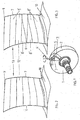
- Fig. 1 shows, in a disc blank 1, starting from the circumferential surface 2, first with the hemispherical cutter head 3 of a - here only schematically illustrated - end mill 4, a channel 5 is cut by roughing. Subsequently, the finishing treatment (finishing) of the side surfaces of the channel 5, that is, the pressure and suction side of a Bliskschaufel 13, by five-axis flank milling with the adjoining a hemispherical cutter head 3 Schheidflanke 11 of the end mill 4. This is a variety of across the Pressure side and the suction side, that is routed between the blade leading edge 6 and the blade trailing edge 7 milling strips 8 of constant strip width milled.
- Fig. 2 shows - with a view to the convex curved suction side 12 - a generated after the milling of two adjacent channels 5, three-dimensionally shaped Bliskschaufel 13 whose running between the blade tip 9 and the annulus 10 and the transition surface to the annulus 10 blade leading edge 6 and blade trailing edge 7 a different Have length.
- the burrs 8 run from the blade leading edge 6 to the blade trailing edge 7 in the prevailing during use of the blisk between the blades flow direction by the burrs 8 are generated during sizing so that they run parallel to the blade tip 9 and the annulus 10 and the Frills 8 are otherwise created to overlap from the longer blade leading edge 6 to the shorter blade trailing edge 7.
- the Fräsersammlung 8 are applied fan-shaped and thereby by the blade tip 9 and the annulus 10 respectively parallel arrangement in the intervening. Range of the inclination at the blade tip the differently oriented inclination at the annulus 10 over.
- the rounded transition from the cutting edge 11 of the end mill 4 to a hemispherical cutter head 3 creates a smooth transition between the adjacent milling cutters 8.
- the milling strips 8 are produced on the printing side, not shown here.
- the Appelrsammlungverlauf thus corresponds to the flow path on both sides of the blade, so that the aerodynamic losses are reduced.
- the aerodynamic losses are further reduced by the fact that the existing between the adjacent Fraser existing heels are overlapped by the overlapping flank milling and thus their size is significantly reduced.
- the effort is reduced in a subsequent polishing the turf areas.
- the milling strips 8 'produced in constant width are applied over a certain part of the blade length without overlapping from the blade leading edge 6 to the blade trailing edge 7 parallel to the course of the blade tip 9 and the further milling strips 8 "in the remaining blade part parallel to the annulus 10
- the intersection of the two areas overlap a blade tip 9 and a ring groove 8 'and 8 "parallel to the annulus 10.
- the milling cutters 8 'parallel to the blade tip 9 can be applied in this form to the highest point on the annulus 10, while the milling cutters 8 "are made only in the remaining small area parallel to the annulus 10.
Landscapes
- Engineering & Computer Science (AREA)
- Mechanical Engineering (AREA)
- Ceramic Engineering (AREA)
- General Engineering & Computer Science (AREA)
- Structures Of Non-Positive Displacement Pumps (AREA)
- Milling Processes (AREA)
Claims (2)
- Procédé de fraisage de disques BLISK (disques aubagés monoblocs) pour moteurs à turbine à gaz, dans lequel une pluralité d'aubes de disque BLISK (13) formée intégralement et tridimensionnelle sont préformées par dégrossissage sur la circonférence d'une ébauche de disque (1), puis terminées par aplanissement du côté refoulement et aspiration ainsi que de la zone de transition annulaire (10), caractérisé en ce que l'aplanissement du côté refoulement et aspiration est réalisé par fraisage sur flanc avec des bandes de fraisage (8, 8', 8") de largeurs égales générées par le flanc de coupe d'un outil de fraisage (4) et dont le tracé correspond au sens d'écoulement entre les aubes de disque BLISK (13) et en ce que les bandes de fraisage (8) entre les bords d'attaque et de fuite de l'aube (6, 7) sont aménagées avec chevauchement en éventail, dans lequel les bandes de fraisage (8) situées sur le bout d'aube (9) et sur la zone de transition annulaire (10) sont parallèles à eux, et l'inclinaison des bandes de fraisage (8) intermédiaires passe progressivement de l'inclinaison de la bande de fraisage sur le bout d'aube à l'inclinaison de la bande de fraisage sur la zone de transition annulaire (10), et dans lequel lorsqu'une bande de fraisage est formée avec chevauchement, l'épaulement formé par la bande de fraisage précédente est finement rectifié.
- Procédé selon une des revendications n° 1,
caractérisé en ce qu'est utilisée comme outil de fraisage une fraise à queue (4) dont le flanc de coupe droit prévu pour découper les bandes de fraisage (8) se raccorde à une tête de fraise hémisphérique.
Applications Claiming Priority (1)
| Application Number | Priority Date | Filing Date | Title |
|---|---|---|---|
| DE102008019332A DE102008019332A1 (de) | 2008-04-16 | 2008-04-16 | Verfahren zum Fräsen von Blisks |
Publications (3)
| Publication Number | Publication Date |
|---|---|
| EP2110193A1 EP2110193A1 (fr) | 2009-10-21 |
| EP2110193B1 EP2110193B1 (fr) | 2011-01-26 |
| EP2110193B2 true EP2110193B2 (fr) | 2018-04-04 |
Family
ID=40601171
Family Applications (1)
| Application Number | Title | Priority Date | Filing Date |
|---|---|---|---|
| EP09156645.5A Ceased EP2110193B2 (fr) | 2008-04-16 | 2009-03-30 | Procédé de fraisage d'un disque aubagé monobloc (Blisk) |
Country Status (4)
| Country | Link |
|---|---|
| US (1) | US20090304473A1 (fr) |
| EP (1) | EP2110193B2 (fr) |
| JP (1) | JP2009262320A (fr) |
| DE (2) | DE102008019332A1 (fr) |
Families Citing this family (31)
| Publication number | Priority date | Publication date | Assignee | Title |
|---|---|---|---|---|
| US11149650B2 (en) | 2007-08-01 | 2021-10-19 | Raytheon Technologies Corporation | Turbine section of high bypass turbofan |
| US11242805B2 (en) | 2007-08-01 | 2022-02-08 | Raytheon Technologies Corporation | Turbine section of high bypass turbofan |
| US11486311B2 (en) | 2007-08-01 | 2022-11-01 | Raytheon Technologies Corporation | Turbine section of high bypass turbofan |
| US11346289B2 (en) | 2007-08-01 | 2022-05-31 | Raytheon Technologies Corporation | Turbine section of high bypass turbofan |
| US8844265B2 (en) | 2007-08-01 | 2014-09-30 | United Technologies Corporation | Turbine section of high bypass turbofan |
| US20150377123A1 (en) | 2007-08-01 | 2015-12-31 | United Technologies Corporation | Turbine section of high bypass turbofan |
| DE102008010252A1 (de) * | 2008-02-20 | 2009-08-27 | Rolls-Royce Deutschland Ltd & Co Kg | Verfahren und Werkzeug zur Annulusbearbeitung eines Gasturbinenrotors mit integral angeformten Schaufeln |
| DE102010033732A1 (de) * | 2010-08-07 | 2012-02-09 | Mtu Aero Engines Gmbh | Verfahren zum Generieren eines Designs eines Bauteils und Verfahren zum Fertigen desselben |
| US8813331B2 (en) | 2011-03-29 | 2014-08-26 | General Electric Company | Process of preparing a turbine rotor wheel, a repair wheel for a turbine rotor wheel, and a turbine rotor wheel |
| CN102785111A (zh) * | 2012-08-23 | 2012-11-21 | 西北工业大学 | 一种整体叶盘数控机床盘铣主轴装置 |
| DE112013005198T5 (de) * | 2012-10-30 | 2015-09-10 | Concepts Eti, Inc. | Verfahren, Systeme und Vorrichtungen zur Gestaltung und Herstellung von flankenfräsbaren Bauteilen |
| US8869504B1 (en) | 2013-11-22 | 2014-10-28 | United Technologies Corporation | Geared turbofan engine gearbox arrangement |
| US9465530B2 (en) * | 2014-04-22 | 2016-10-11 | Concepts Nrec, Llc | Methods, systems, and devices for designing and manufacturing flank millable components |
| EP3012411B1 (fr) * | 2014-10-23 | 2025-05-21 | RTX Corporation | Rotor à aubage intégral ayant un bras axial et une poche |
| GB2542124B (en) * | 2015-09-08 | 2019-06-05 | Technicut Ltd | Method and tools for manufacturing a bladed disk |
| ITUB20161145A1 (it) * | 2016-02-29 | 2017-08-29 | Exergy Spa | Metodo per la costruzione di anelli palettati per turbomacchine radiali e anello palettato ottenuto tramite tale metodo |
| ITUA20162126A1 (it) * | 2016-03-30 | 2017-09-30 | Exergy Spa | Metodo per la costruzione di dischi palettati per turbomacchine radiali e disco palettato ottenuto tramite tale metodo |
| CN108405941B (zh) * | 2018-02-28 | 2020-02-18 | 上海交通大学 | 航空发动机叶片叶身型面高效精密铣削加工方法 |
| CN108762080B (zh) * | 2018-06-04 | 2019-12-20 | 西北工业大学 | 四轴粗加工轴流式整体叶盘中刀具底刃切削评估及进给速度优化方法 |
| CN109093130A (zh) * | 2018-08-08 | 2018-12-28 | 西北工业大学 | 基于分区域加工的薄壁环形零件粗加工工艺优化方法 |
| US11156092B2 (en) * | 2019-02-07 | 2021-10-26 | Honeywell International Inc. | Multistage axial-centrifugal compressor systems and methods for manufacture |
| CN110076379B (zh) * | 2019-04-30 | 2020-05-22 | 沈阳透平机械股份有限公司 | 离心压缩机的叶轮叶片二次精加工方法及叶轮叶片 |
| JP6684977B1 (ja) * | 2019-08-30 | 2020-04-22 | ヤマザキマザック株式会社 | 統合回転翼の製造方法及びそのブレードの切削加工プログラム |
| EP3834974A1 (fr) * | 2019-12-12 | 2021-06-16 | GF Machining Solutions AG | Procédé de fabrication d'une pièce à paroi mince |
| CN111774821B (zh) * | 2020-08-01 | 2024-08-13 | 石家庄长兴基业铁路配件有限公司 | 一种铝型材双面铲翅自动化生产线 |
| CN111958194B (zh) * | 2020-08-18 | 2022-02-25 | 哈尔滨汽轮机厂有限责任公司 | 一种带预扭角叶片叶冠汽封齿加工方法 |
| CN112207524B (zh) * | 2020-08-26 | 2022-07-19 | 成都市新美加机械设备制造有限公司 | 一种小叶片加工工艺 |
| CN112404539A (zh) * | 2020-09-28 | 2021-02-26 | 中国航发沈阳黎明航空发动机有限责任公司 | 一种整体叶盘粗铣加工方法 |
| CN114192857B (zh) * | 2021-12-10 | 2023-03-28 | 台州中驰智谷科技有限公司 | 一种用于加工航空发动机叶轮的刀具 |
| CN115555800B (zh) * | 2022-06-30 | 2025-07-01 | 苏州千机智能软件有限公司 | 一种带分流叶片的离心叶轮的组合铣加工方法 |
| CN119387658B (zh) * | 2024-10-31 | 2025-09-30 | 哈尔滨汽轮机厂有限责任公司 | 一种大锥度压气机导叶片的加工方法 |
Citations (9)
| Publication number | Priority date | Publication date | Assignee | Title |
|---|---|---|---|---|
| US1933798A (en) † | 1930-01-22 | 1933-11-07 | Gebers Friedrich | Manufacture of propellers |
| US2633776A (en) † | 1948-08-14 | 1953-04-07 | Kellogg M W Co | Method of manufacturing turbine blades integral with turbine rotor |
| US3127506A (en) † | 1955-11-07 | 1964-03-31 | Onera (Off Nat Aerospatiale) | Machine control |
| DE2544612B2 (de) † | 1974-10-14 | 1978-11-30 | Leningradskoe Specialnoe Konstruktorskoe Bjuro Tyaschelych I Unikalnych Stankov, Leningrad (Sowjetunion) | Rundfräsverfahren |
| JPS6144521A (ja) † | 1984-08-02 | 1986-03-04 | Mitsubishi Heavy Ind Ltd | 薄肉曲面加工法 |
| US4596501A (en) † | 1984-02-08 | 1986-06-24 | Pratt & Whitney Canada Inc. | Multiple cutter pass flank milling |
| US20030039547A1 (en) † | 2001-08-23 | 2003-02-27 | Snecma-Moteurs | Method of manufacturing an integral rotor blade disk and corresponding disk |
| GB2385815A (en) † | 2002-03-01 | 2003-09-03 | Alstom | Method of manufacturing turbine blades |
| DE10312224B3 (de) † | 2003-03-19 | 2004-10-28 | Mtu Aero Engines Gmbh | Verfahren zum Herstellen von strömungsbeaufschlagten Bauteilen |
Family Cites Families (6)
| Publication number | Priority date | Publication date | Assignee | Title |
|---|---|---|---|---|
| JPS6144522A (ja) * | 1984-08-03 | 1986-03-04 | Mitsubishi Heavy Ind Ltd | プロペラの製造方法 |
| JPH06206112A (ja) * | 1993-01-12 | 1994-07-26 | Fuji Electric Co Ltd | 大形ランナベーン翼面の加工方法 |
| ES2102885T3 (es) * | 1993-09-29 | 1997-08-01 | Siemens Ag | Procedimiento para fresar un perfil de alabe de turbina que se extiende a lo largo de un eje principal. |
| JPH09262713A (ja) * | 1996-03-29 | 1997-10-07 | Toyota Central Res & Dev Lab Inc | ボールエンドミル |
| US6077002A (en) | 1998-10-05 | 2000-06-20 | General Electric Company | Step milling process |
| US7637010B2 (en) * | 2005-12-01 | 2009-12-29 | General Electric Company | Methods for machining turbine engine components |
-
2008
- 2008-04-16 DE DE102008019332A patent/DE102008019332A1/de not_active Withdrawn
-
2009
- 2009-03-30 EP EP09156645.5A patent/EP2110193B2/fr not_active Ceased
- 2009-03-30 DE DE502009000337T patent/DE502009000337D1/de active Active
- 2009-04-09 JP JP2009094651A patent/JP2009262320A/ja active Pending
- 2009-04-16 US US12/385,712 patent/US20090304473A1/en not_active Abandoned
Patent Citations (9)
| Publication number | Priority date | Publication date | Assignee | Title |
|---|---|---|---|---|
| US1933798A (en) † | 1930-01-22 | 1933-11-07 | Gebers Friedrich | Manufacture of propellers |
| US2633776A (en) † | 1948-08-14 | 1953-04-07 | Kellogg M W Co | Method of manufacturing turbine blades integral with turbine rotor |
| US3127506A (en) † | 1955-11-07 | 1964-03-31 | Onera (Off Nat Aerospatiale) | Machine control |
| DE2544612B2 (de) † | 1974-10-14 | 1978-11-30 | Leningradskoe Specialnoe Konstruktorskoe Bjuro Tyaschelych I Unikalnych Stankov, Leningrad (Sowjetunion) | Rundfräsverfahren |
| US4596501A (en) † | 1984-02-08 | 1986-06-24 | Pratt & Whitney Canada Inc. | Multiple cutter pass flank milling |
| JPS6144521A (ja) † | 1984-08-02 | 1986-03-04 | Mitsubishi Heavy Ind Ltd | 薄肉曲面加工法 |
| US20030039547A1 (en) † | 2001-08-23 | 2003-02-27 | Snecma-Moteurs | Method of manufacturing an integral rotor blade disk and corresponding disk |
| GB2385815A (en) † | 2002-03-01 | 2003-09-03 | Alstom | Method of manufacturing turbine blades |
| DE10312224B3 (de) † | 2003-03-19 | 2004-10-28 | Mtu Aero Engines Gmbh | Verfahren zum Herstellen von strömungsbeaufschlagten Bauteilen |
Non-Patent Citations (1)
| Title |
|---|
| URS BLATTER: "Effiziente Bliskfertigung mit Starrag -Software-Modul PSI_F", PSI5D/USERS GUIDE, vol. 20, 1 January 1998 (1998-01-01), CALIFORNIA/USA † |
Also Published As
| Publication number | Publication date |
|---|---|
| US20090304473A1 (en) | 2009-12-10 |
| DE102008019332A1 (de) | 2009-10-22 |
| EP2110193A1 (fr) | 2009-10-21 |
| EP2110193B1 (fr) | 2011-01-26 |
| JP2009262320A (ja) | 2009-11-12 |
| DE502009000337D1 (de) | 2011-03-10 |
Similar Documents
| Publication | Publication Date | Title |
|---|---|---|
| EP2110193B1 (fr) | Procédé de fraisage d'un disque aubagé monobloc (Blisk) | |
| EP3473431B1 (fr) | Pale et rotor pour une turbomachine ainsi que turbomachine | |
| DE69931324T2 (de) | Schrittfräsmethode | |
| EP2106876B1 (fr) | Procédé de mise en forme aérodynamique du bord d'attaque d'une aube d'un disque aubage monobloc | |
| EP2093012B1 (fr) | Méthode pour l'usinage d'un anneau d'un rotor d'une turbine à gaz avec des aubes integrées | |
| EP2106877B1 (fr) | Procédé de fabrication d'un disque aubagé monobloc | |
| EP0972128B1 (fr) | Structure superficielle pour la paroi d'un canal d'ecoulement ou d'une aube de turbine | |
| EP3467261B1 (fr) | Procédé de fabrication d'un élément d'aube en tandem | |
| DE60317522T2 (de) | Maschinelle bearbeitung von turbinenrotoren unter verwendung von becherwerkzeugen | |
| EP1774179B1 (fr) | Aube de compresseur | |
| EP2617945B1 (fr) | Rotor pour une turbomachine et procédé de fabrication | |
| EP3287221B1 (fr) | Procédé de traitement de flancs de dents de pièces d'usinage d'accouplement plan selon un procédé de pièces individuelles semi-complètes | |
| DE102016211223A1 (de) | Spanendes Fertigungsverfahren zur Herstellung von Schaufelfußaufnahmen | |
| EP1967307B1 (fr) | Procédé de fabrication d'un élément de moyeu de rotor pourvu de rainures | |
| WO2009127204A1 (fr) | Étage de stator et/ou de rotor de compresseur axial de turbomachine à éléments de guidage de l'écoulement destinés à augmenter le rendement | |
| EP3093100A1 (fr) | Production de canaux d'aube de rotors de turbomachine | |
| EP4073352B1 (fr) | Roteur pour une turbomachine et turbomachine | |
| EP1393836B1 (fr) | Méthode de fabrication d'ébauches pour éléments aubagés et matrice de forgeage | |
| EP3183430B1 (fr) | Aube mobile de turbine | |
| EP1798376B1 (fr) | Méthode pour la fabrication d'un canal pour un flux secondaire | |
| WO2012019584A1 (fr) | Procédé pour créer une conception d'un élément et procédé pour fabriquer ce dernier | |
| DE102019118072A1 (de) | Rotor und Verfahren zum Herstellen eines Rotors | |
| EP2860352A1 (fr) | Rotor, procédé de manufacture et aube associés | |
| EP2639004B1 (fr) | Segment de couronne d'aubes avec surface de limitation de l'espace annulaire à profil en hauteur ondulé et procédé de fabrication | |
| EP4341532B1 (fr) | Procédé d'équilibrage de roues de turbine des turbines à gaz d'échappement, et roue de turbine équilibrée |
Legal Events
| Date | Code | Title | Description |
|---|---|---|---|
| PUAI | Public reference made under article 153(3) epc to a published international application that has entered the european phase |
Free format text: ORIGINAL CODE: 0009012 |
|
| 17P | Request for examination filed |
Effective date: 20090605 |
|
| AK | Designated contracting states |
Kind code of ref document: A1 Designated state(s): AT BE BG CH CY CZ DE DK EE ES FI FR GB GR HR HU IE IS IT LI LT LU LV MC MK MT NL NO PL PT RO SE SI SK TR |
|
| AX | Request for extension of the european patent |
Extension state: AL BA RS |
|
| GRAP | Despatch of communication of intention to grant a patent |
Free format text: ORIGINAL CODE: EPIDOSNIGR1 |
|
| AKX | Designation fees paid |
Designated state(s): DE FR GB |
|
| GRAS | Grant fee paid |
Free format text: ORIGINAL CODE: EPIDOSNIGR3 |
|
| GRAA | (expected) grant |
Free format text: ORIGINAL CODE: 0009210 |
|
| AK | Designated contracting states |
Kind code of ref document: B1 Designated state(s): DE FR GB |
|
| REG | Reference to a national code |
Ref country code: GB Ref legal event code: FG4D Free format text: NOT ENGLISH |
|
| REF | Corresponds to: |
Ref document number: 502009000337 Country of ref document: DE Date of ref document: 20110310 Kind code of ref document: P |
|
| REG | Reference to a national code |
Ref country code: DE Ref legal event code: R096 Ref document number: 502009000337 Country of ref document: DE Effective date: 20110310 |
|
| PLBI | Opposition filed |
Free format text: ORIGINAL CODE: 0009260 |
|
| PLAX | Notice of opposition and request to file observation + time limit sent |
Free format text: ORIGINAL CODE: EPIDOSNOBS2 |
|
| 26 | Opposition filed |
Opponent name: MTU AERO ENGINES GMBH Effective date: 20111026 Opponent name: STARRAGHECKERT AG Effective date: 20111026 |
|
| REG | Reference to a national code |
Ref country code: DE Ref legal event code: R026 Ref document number: 502009000337 Country of ref document: DE Effective date: 20111026 |
|
| PLBB | Reply of patent proprietor to notice(s) of opposition received |
Free format text: ORIGINAL CODE: EPIDOSNOBS3 |
|
| REG | Reference to a national code |
Ref country code: FR Ref legal event code: PLFP Year of fee payment: 8 |
|
| REG | Reference to a national code |
Ref country code: FR Ref legal event code: PLFP Year of fee payment: 9 |
|
| PUAH | Patent maintained in amended form |
Free format text: ORIGINAL CODE: 0009272 |
|
| STAA | Information on the status of an ep patent application or granted ep patent |
Free format text: STATUS: PATENT MAINTAINED AS AMENDED |
|
| REG | Reference to a national code |
Ref country code: FR Ref legal event code: PLFP Year of fee payment: 10 |
|
| 27A | Patent maintained in amended form |
Effective date: 20180404 |
|
| AK | Designated contracting states |
Kind code of ref document: B2 Designated state(s): DE FR GB |
|
| REG | Reference to a national code |
Ref country code: DE Ref legal event code: R102 Ref document number: 502009000337 Country of ref document: DE |
|
| PGFP | Annual fee paid to national office [announced via postgrant information from national office to epo] |
Ref country code: GB Payment date: 20200327 Year of fee payment: 12 Ref country code: DE Payment date: 20200327 Year of fee payment: 12 |
|
| PGFP | Annual fee paid to national office [announced via postgrant information from national office to epo] |
Ref country code: FR Payment date: 20200325 Year of fee payment: 12 |
|
| REG | Reference to a national code |
Ref country code: DE Ref legal event code: R119 Ref document number: 502009000337 Country of ref document: DE |
|
| GBPC | Gb: european patent ceased through non-payment of renewal fee |
Effective date: 20210330 |
|
| PG25 | Lapsed in a contracting state [announced via postgrant information from national office to epo] |
Ref country code: FR Free format text: LAPSE BECAUSE OF NON-PAYMENT OF DUE FEES Effective date: 20210331 Ref country code: GB Free format text: LAPSE BECAUSE OF NON-PAYMENT OF DUE FEES Effective date: 20210330 Ref country code: DE Free format text: LAPSE BECAUSE OF NON-PAYMENT OF DUE FEES Effective date: 20211001 |