EP2110316B1 - Dispositif pour transférer du matériau en vrac stocké dans un réservoir - Google Patents
Dispositif pour transférer du matériau en vrac stocké dans un réservoir Download PDFInfo
- Publication number
- EP2110316B1 EP2110316B1 EP08007280A EP08007280A EP2110316B1 EP 2110316 B1 EP2110316 B1 EP 2110316B1 EP 08007280 A EP08007280 A EP 08007280A EP 08007280 A EP08007280 A EP 08007280A EP 2110316 B1 EP2110316 B1 EP 2110316B1
- Authority
- EP
- European Patent Office
- Prior art keywords
- perforated plate
- individual products
- product
- width
- bulk material
- Prior art date
- Legal status (The legal status is an assumption and is not a legal conclusion. Google has not performed a legal analysis and makes no representation as to the accuracy of the status listed.)
- Not-in-force
Links
- 239000013590 bulk material Substances 0.000 title claims description 13
- 238000000926 separation method Methods 0.000 description 4
- 239000000428 dust Substances 0.000 description 3
- 238000003856 thermoforming Methods 0.000 description 3
- 230000008878 coupling Effects 0.000 description 2
- 238000010168 coupling process Methods 0.000 description 2
- 238000005859 coupling reaction Methods 0.000 description 2
- 238000001556 precipitation Methods 0.000 description 2
- 230000000284 resting effect Effects 0.000 description 2
- 230000006978 adaptation Effects 0.000 description 1
- 230000015572 biosynthetic process Effects 0.000 description 1
- 238000004140 cleaning Methods 0.000 description 1
- 239000008298 dragée Substances 0.000 description 1
- 230000000694 effects Effects 0.000 description 1
- 230000002349 favourable effect Effects 0.000 description 1
- 230000005484 gravity Effects 0.000 description 1
- 238000010438 heat treatment Methods 0.000 description 1
- 230000003993 interaction Effects 0.000 description 1
- 239000010410 layer Substances 0.000 description 1
- 239000006187 pill Substances 0.000 description 1
- 239000002356 single layer Substances 0.000 description 1
- 239000003826 tablet Substances 0.000 description 1
Images


Classifications
-
- B—PERFORMING OPERATIONS; TRANSPORTING
- B65—CONVEYING; PACKING; STORING; HANDLING THIN OR FILAMENTARY MATERIAL
- B65B—MACHINES, APPARATUS OR DEVICES FOR, OR METHODS OF, PACKAGING ARTICLES OR MATERIALS; UNPACKING
- B65B37/00—Supplying or feeding fluent-solid, plastic, or liquid material, or loose masses of small articles, to be packaged
- B65B37/04—Supplying or feeding fluent-solid, plastic, or liquid material, or loose masses of small articles, to be packaged by vibratory feeders
-
- B—PERFORMING OPERATIONS; TRANSPORTING
- B65—CONVEYING; PACKING; STORING; HANDLING THIN OR FILAMENTARY MATERIAL
- B65B—MACHINES, APPARATUS OR DEVICES FOR, OR METHODS OF, PACKAGING ARTICLES OR MATERIALS; UNPACKING
- B65B35/00—Supplying, feeding, arranging or orientating articles to be packaged
- B65B35/06—Separating single articles from loose masses of articles
- B65B35/08—Separating single articles from loose masses of articles using pocketed conveyors
-
- B—PERFORMING OPERATIONS; TRANSPORTING
- B65—CONVEYING; PACKING; STORING; HANDLING THIN OR FILAMENTARY MATERIAL
- B65B—MACHINES, APPARATUS OR DEVICES FOR, OR METHODS OF, PACKAGING ARTICLES OR MATERIALS; UNPACKING
- B65B5/00—Packaging individual articles in containers or receptacles, e.g. bags, sacks, boxes, cartons, cans, jars
- B65B5/08—Packaging groups of articles, the articles being individually gripped or guided for transfer to the containers or receptacles
Definitions
- the invention relates to a device for transferring in a reservoir, stored, formed from individual products bulk material to a the individual products in the wells of a continuously or cyclically moving film web transfer transfer device, with a product outlet of the reservoir downstream downstream perforated plate.
- Such devices are used, in particular, as part of a workstation in thermoforming machines, which transfer individual products to be packed in blister packs to the transfer device for further processing.
- the individual products are given as bulk material through the outlet opening of the product outlet on the perforated plate, which serves to promote a possible single-layer product carpet in the direction of transfer device and thereby cause a dust and Bruchauschtung through the holes of the perforated plate , Directly below the outlet opening of the product outlet, the perforated plate must have no holes, since the resting on the perforated plate individual products are pressed by the overlying product column on the perforated plate, which is damaged by the edges of the holes could lead to more breakage, which would subsequently have to be eliminated.
- the invention is therefore based on the object, a device of the type mentioned in such a way that the effectiveness of the dust and Bruchausscheidung the perforated plate is increased.
- outlet opening of the product outlet has an oriented on a rectangle basic shape with a 60-95% of the width of the perforated plate corresponding width, and that the perforated plate below the product outlet a product inlet surface free of holes, and that the product inlet surface has 3 to 8 times the size of the outlet opening.
- This set up of the device achieves the advantage that the available length of the perforated plate is better utilized because, in contrast to a round outlet opening of the product outlet, the product inlet area can be smaller, namely shorter.
- Another advantage results from the fact that the shape of the outlet opening is oriented with respect to their width on the width of the perforated plate, so that in the conveying direction only a shorter length of the perforated plate is needed to fan the product carpet to the full width of the perforated plate. It is also favorable that the individual products from the product column can fan out into a product carpet before the holes in the perforated plate are reached, thus reducing the risk of breakage.
- a lower load also results from the fact that in the rectangular design of the outlet opening the volume of the product column over the product inlet surface is smaller and thus results in a smaller volume flowed through by the individual products in the product outlet, so that with an equal number of individual products flowing through the residence time the individual products in the product column are reduced, thereby reducing the risk of damaging the individual products in the product column.
- the outlet opening is rectangular in shape with a 75-85% of the width of the perforated plate corresponding width
- a particularly high surface efficiency of the perforated plate results as the ratio of the areas under the product outlet to the effective perforated plate surface, since the product inlet surface is tuned in the conveying direction to the size of the outlet opening, which in turn is based on the size of the individual products, although quite individual products Size can be processed with the device according to the invention within the above-mentioned intervals.
- a plurality of perforated plate are provided in a direction perpendicular to the conveying direction Reihung.
- the performance of the device according to the invention is thereby significantly increased in a simple manner, that two perforated plates arranged side by side are used, whose overall width determines the effective width at which the dimensioning of the outlet opening is oriented.
- a high utilization efficiency of the product outlet is achieved, which is defined as the ratio of the width of the product outlet to the effective useful width of the perforated plates.
- a utilization efficiency of approximately 0.9 is achieved, which is significantly increased compared to previously known embodiments.
- the perforated plate arranged on a plate holder is assigned at least one vibration drive for conveying the products from the product outlet to the transfer device.
- Thermoforming machines are used in particular in the pharmaceutical industry to package individual products such as tablets, dragees, pills or the like in blister packs, for which initially a thermoforming machine is withdrawn from a supply roll as a film web and fed to a heating station in which the mold film is heated to deformation temperature and a forming station is fed, in which the wells of the blister packs are formed. In the so-trained wells then the individual products must be transferred, which are provided as bulk material.
- the device according to the invention ( Fig. 1 ) as a coupling member between the reservoir 1 and the individual products in the wells of the film web transfer transfer device.
- the device according to the invention comprises in addition to the reservoir 1 with its product outlet 2 on a base frame 24 in a plate holder 3 releasably and replaceably arranged perforated plate 4, which is downstream of the product outlet 2 downstream.
- the perforated plate 4 is multiple, namely twice present in a direction perpendicular to the conveying direction of the individual products Reihung, thereby resulting in a very simple manner, an effective wide useful width.
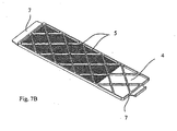
- Each perforated plate 4 has a plurality of holes adapted to the diameter and the shape of the individual products, which retain intact individual products on the surface of the perforated plate 4, but allow the separation of breakage and dust.
- stiffening ribs 5 On the side facing away from the individual products of the perforated plates 4 are stiffening ribs 5 ( Fig.
- the area directly under the product outlet 2 can not be used for fractional precipitation, since the resting on the perforated plate 4 Single products would be pressed from above through the overlying product column on the perforated plate 4 and the edges of the holes and the vibration movements of the perforated plate 4 could damage the individual products.
- the area below the product outlet 2 must therefore remain free of holes and is thus lost for the fractional precipitation, thereby resulting in an extension of the perforated plate 4, in order to achieve a complete product separation. Therefore, the requirements for the smallest possible space requirement with the highest possible performance existed as framework conditions.
- the outlet opening 21 of the product outlet 2 has a rectangular shape oriented to a width of the perforated plate 4 approximate width and aligned to the size of the individual products length, the perforated plate 4 below the product outlet with a Having the length of the outlet opening 21 corresponding product inlet surface 22 free of holes.
- the entire width of the perforated plate 4 is utilized for the product separation in the application of the individual products on the perforated plate 4, so that there is a corresponding adjustment of the outlet opening 21 of the product outlet 2.
- the length of the hole-free area of the perforated plate 4 is limited and minimizes the area that does not contribute to breakage, since initially the individual products extending from the edges of the product outlet 21 to the Have to distribute edges of the perforated plate 4. It has proven to be advantageous if the outlet opening 21 is designed rectangular with a 60 to 95%, in particular 75 to 85% of the width of the perforated plate 4 corresponding width and 2 to 12 times, in particular 5 to 8 times length corresponding to the size of the products, wherein the product inlet surface 22 has 3 to 8 times the size of the outlet opening 21 ( Fig. 8 ).
- a bulk material leveler 9 rotatable about a pivot axis 8 is arranged downstream of the perforated plate 4, which is detachably connected to the base frame 24 in order to enable the change of the perforated plates 4 located underneath the bulk material leveler 9.
- the bulk leveler 9 itself has at its the perforated plate 4 facing the free end of an elastic lip 10 to ensure a gentle treatment of the individual products; the rotational position of the bulk material leveler 9 itself can be fixed by a fixing element 11, namely a clamping screw with a toggle wheel, in order to allow adaptation to the size of the individual products ( Fig. 10 ).
- a fixing element 11 namely a clamping screw with a toggle wheel
- On the clamping screw itself an adjusting lever 12 is arranged.
- the clamping screw is first loosened and twisted with the adjusting lever 12 of the bulk material leveler 9 so that it can be removed from an upwardly open screw holder 13 upwards.
- the simple interchangeability of the perforated plates 4 is given by the use of the plate holder 3 as a slide support 15 arranged terminal strips 14.
- Each terminal block 14 is mounted in a slide carrier 15 with a sloping to the vertical backdrop 16, wherein the gate 16 through an open end cam 17 is formed, in which the terminal block 14 with a guide pin 18 can be used.
- a clamping means On the opposite side of the gate 16 of the terminal strips 14 is a clamping means, namely a clamping screw 19 is arranged, which engages in a downwardly inclined to the vertical guided screw bearing 23, wherein the inclination direction of the link 16 of the inclination direction of the clamping screw 19 corresponds, so that at a rotation of the clamping screws 19 in the clamping direction, the terminal block 14 is pulled downwards in total according to the inclination and clamps the perforated plate 4 against the plate holder 3.
- the clamping screw 19 is releasably attached to the terminal block 14 ( FIGS. 6a to 6c ).
- the FIGS. 1 to 3 show that the terminal block 14 is provided several times in a side edges of the perforated plate 4 associated arrangement.
- the middle clamping bar 14 serves to load the two side edges of the left and right perforated plates 4.
- the presence of the middle clamping bar 14 also forces the formation of a receptacle 20 in the bulk material leveler 9.
Landscapes
- Engineering & Computer Science (AREA)
- Mechanical Engineering (AREA)
- Treatment Of Fiber Materials (AREA)
- Auxiliary Devices For And Details Of Packaging Control (AREA)
- Control And Other Processes For Unpacking Of Materials (AREA)
Claims (3)
- Dispositif destiné au transfert de matière en vrac, stockée dans un réservoir (1) et formée de produits individuels, sur un dispositif de transfert transférant les produits individuels dans les alvéoles d'une bande de feuille déplacée en continue ou en cadence, comprenant une plaque perforée (4) montée en aval de la sortie de produits (2) du réservoir (1), la plaque perforée (4) présentant au-dessous de la sortie de produits (2) une surface d'arrivée de produits (22) exempte de trous,
caractérisé en ce que
l'ouverture de sortie (21) de la sortie de produits (2) présente une forme de base orientée sur un rectangle, d'une largeur correspondante à 60 - 95% de la largeur de la plaque perforée (4), et que la surface d'arrivée de produits (22) présente la dimension 3 à 8 fois l'ouverture de sortie (21). - Dispositif suivant la revendication 1, caractérisé en ce que l'ouverture de sortie (21) a une configuration rectangulaire, avec une largeur correspondant à 75 - 85% de la largeur de la plaque perforée (4).
- Dispositif suivant l'une des revendications 1 et 2, caractérisé en ce qu'au moins un entraînement vibratoire pour le transport des produits de la sortie (2) au dispositif de transfert est associé à la plaque perforée (4), disposée sur une fixation de plaque (3).
Priority Applications (2)
| Application Number | Priority Date | Filing Date | Title |
|---|---|---|---|
| EP08007280A EP2110316B8 (fr) | 2008-04-14 | 2008-04-14 | Dispositif pour transférer du matériau en vrac stocké dans un réservoir |
| US12/422,789 US20090255856A1 (en) | 2008-04-14 | 2009-04-13 | Device for Delivering Bulk Material Stored in a Supply Container |
Applications Claiming Priority (1)
| Application Number | Priority Date | Filing Date | Title |
|---|---|---|---|
| EP08007280A EP2110316B8 (fr) | 2008-04-14 | 2008-04-14 | Dispositif pour transférer du matériau en vrac stocké dans un réservoir |
Publications (3)
| Publication Number | Publication Date |
|---|---|
| EP2110316A1 EP2110316A1 (fr) | 2009-10-21 |
| EP2110316B1 true EP2110316B1 (fr) | 2012-06-20 |
| EP2110316B8 EP2110316B8 (fr) | 2012-09-05 |
Family
ID=39683810
Family Applications (1)
| Application Number | Title | Priority Date | Filing Date |
|---|---|---|---|
| EP08007280A Not-in-force EP2110316B8 (fr) | 2008-04-14 | 2008-04-14 | Dispositif pour transférer du matériau en vrac stocké dans un réservoir |
Country Status (2)
| Country | Link |
|---|---|
| US (1) | US20090255856A1 (fr) |
| EP (1) | EP2110316B8 (fr) |
Families Citing this family (1)
| Publication number | Priority date | Publication date | Assignee | Title |
|---|---|---|---|---|
| WO2020202039A1 (fr) | 2019-04-05 | 2020-10-08 | Blue Sky Ventures (Ontario) Inc. | Transporteur vibrant destiné à transporter des articles, machine et procédés de remplissage associés |
Family Cites Families (7)
| Publication number | Priority date | Publication date | Assignee | Title |
|---|---|---|---|---|
| US5191741A (en) * | 1991-07-25 | 1993-03-09 | Mcneil-Ppc, Inc. | Fluidized bed bottle filling system |
| IT1279731B1 (it) * | 1995-09-27 | 1997-12-16 | Ima Spa | Dispositivo per il riempimento di nastri alveolati con articoli |
| US6568151B2 (en) * | 2001-02-07 | 2003-05-27 | Kalish, Inc. | Conveyor for use in contamination sensitive equipment |
| DE10319348A1 (de) * | 2003-04-30 | 2004-11-18 | Robert Bosch Gmbh | Vorrichtung zum geordneten Zuführen von Produkten |
| DE102006007136A1 (de) * | 2005-06-03 | 2006-12-07 | Wolfgang Zieher | Vorrichtung zur Individual-Verpackung von Tabletten nach enem Multi-Dose-System |
| DE102005049882B3 (de) * | 2005-10-17 | 2007-02-01 | Uhlmann Pac-Systeme Gmbh & Co. Kg. | Vorrichtung zum geordneten Zuführen und Ablegen zu verpackender Kleinteile in die Näpfe einer Folienbahn |
| DE102006022262B3 (de) * | 2006-05-11 | 2007-11-29 | Uhlmann Pac-Systeme Gmbh & Co Kg | Vorrichtung zum geordneten Zuführen und Ablegen zu verpackender Kleinteile in die Näpfe einer Folienbahn |
-
2008
- 2008-04-14 EP EP08007280A patent/EP2110316B8/fr not_active Not-in-force
-
2009
- 2009-04-13 US US12/422,789 patent/US20090255856A1/en not_active Abandoned
Also Published As
| Publication number | Publication date |
|---|---|
| EP2110316A1 (fr) | 2009-10-21 |
| US20090255856A1 (en) | 2009-10-15 |
| EP2110316B8 (fr) | 2012-09-05 |
Similar Documents
| Publication | Publication Date | Title |
|---|---|---|
| EP2110318B1 (fr) | Dispositif pour transférer de matière en vrac stockée dans un réservoir | |
| DE2541914C3 (de) | Vorrichtung zum Einbringen von Zwischenlagen zwischen Fleischbällchen o.dgl | |
| DE69835716T2 (de) | Anlage für das Verpacken von Produkten | |
| DE69704140T2 (de) | Vorrichtung zum Entladen von Verpackungen aus einem Förderer | |
| EP2353149B1 (fr) | Procédé et installation de transport pour le recyclage d'emballages vides en retour, en particulier de bouteilles et de boîtes | |
| DD295326A5 (de) | Verfahren und vorrichtung zum sukzessiven zufuehren flacher produkte | |
| DE2929851C2 (fr) | ||
| DD287460A5 (de) | Verfahren und vorrichtung zum aufeinanderfolgenden foerdern von flachen gegenstaenden | |
| DE60308229T2 (de) | Vorrichtung zur lagerung und zuführung von produkten | |
| CH656858A5 (de) | Einrichtung zum vereinzeln und ggf. zum zufuehren von montageteilen. | |
| DE60202021T2 (de) | Verteilungsvorrichtung | |
| EP2110316B1 (fr) | Dispositif pour transférer du matériau en vrac stocké dans un réservoir | |
| DE60001034T2 (de) | Vorrichtung zum Zuführen von Tabletten in einer Verpackungsmaschine | |
| EP2110317A1 (fr) | Dispositif pour transférer de matière en vrac stockée dans un réservoir | |
| DE2546599A1 (de) | Foerdereinrichtung fuer zigaretten | |
| DE922852C (de) | Tablettenzufuehrungsvorrichtung | |
| EP1775219A2 (fr) | Dispositif pour alimenter et disposer de façon ordonnée des petites produits à emballer dans les alvéoles d'un film | |
| EP1975072A1 (fr) | Dispositif d'alimentation | |
| DE10222760A1 (de) | Mogulmaschine und Verfahren für die Herstellung von in Puder gegossenen Produkten | |
| DE3231464C2 (fr) | ||
| EP2955116A1 (fr) | Dispositif et procédé de guidage de produits dans des jattes de plaquettes thermoformées | |
| DE4338839C1 (de) | Vorrichtung zum Vereinzeln von quaderförmigen Stäbchen aus tiefgefrorenem Lebensmittel | |
| DE1556694C3 (de) | Vorrichtung zum Ausrichten von Ampullen in eine gleichmäßige Reihenfolge | |
| DE69915473T2 (de) | Verfahren und Vorrichtung zur Übertragung von Produkten in eine gewisse Ebene | |
| DE3045365C2 (fr) |
Legal Events
| Date | Code | Title | Description |
|---|---|---|---|
| PUAI | Public reference made under article 153(3) epc to a published international application that has entered the european phase |
Free format text: ORIGINAL CODE: 0009012 |
|
| 17P | Request for examination filed |
Effective date: 20080926 |
|
| AK | Designated contracting states |
Kind code of ref document: A1 Designated state(s): AT BE BG CH CY CZ DE DK EE ES FI FR GB GR HR HU IE IS IT LI LT LU LV MC MT NL NO PL PT RO SE SI SK TR |
|
| AX | Request for extension of the european patent |
Extension state: AL BA MK RS |
|
| AKX | Designation fees paid |
Designated state(s): DE FR GB IE IT SE |
|
| GRAP | Despatch of communication of intention to grant a patent |
Free format text: ORIGINAL CODE: EPIDOSNIGR1 |
|
| GRAS | Grant fee paid |
Free format text: ORIGINAL CODE: EPIDOSNIGR3 |
|
| GRAA | (expected) grant |
Free format text: ORIGINAL CODE: 0009210 |
|
| AK | Designated contracting states |
Kind code of ref document: B1 Designated state(s): DE FR GB IE IT SE |
|
| REG | Reference to a national code |
Ref country code: GB Ref legal event code: FG4D Free format text: NOT ENGLISH |
|
| REG | Reference to a national code |
Ref country code: IE Ref legal event code: FG4D Free format text: LANGUAGE OF EP DOCUMENT: GERMAN |
|
| REG | Reference to a national code |
Ref country code: DE Ref legal event code: R096 Ref document number: 502008007439 Country of ref document: DE Effective date: 20120816 |
|
| RIN2 | Information on inventor provided after grant (corrected) |
Inventor name: MAUZ, HARALD Inventor name: GNANN, KURT |
|
| PG25 | Lapsed in a contracting state [announced via postgrant information from national office to epo] |
Ref country code: SE Free format text: LAPSE BECAUSE OF FAILURE TO SUBMIT A TRANSLATION OF THE DESCRIPTION OR TO PAY THE FEE WITHIN THE PRESCRIBED TIME-LIMIT Effective date: 20120620 |
|
| PLBE | No opposition filed within time limit |
Free format text: ORIGINAL CODE: 0009261 |
|
| STAA | Information on the status of an ep patent application or granted ep patent |
Free format text: STATUS: NO OPPOSITION FILED WITHIN TIME LIMIT |
|
| 26N | No opposition filed |
Effective date: 20130321 |
|
| REG | Reference to a national code |
Ref country code: DE Ref legal event code: R097 Ref document number: 502008007439 Country of ref document: DE Effective date: 20130321 |
|
| PGFP | Annual fee paid to national office [announced via postgrant information from national office to epo] |
Ref country code: DE Payment date: 20130426 Year of fee payment: 6 |
|
| PGFP | Annual fee paid to national office [announced via postgrant information from national office to epo] |
Ref country code: IT Payment date: 20130419 Year of fee payment: 6 |
|
| GBPC | Gb: european patent ceased through non-payment of renewal fee |
Effective date: 20130414 |
|
| REG | Reference to a national code |
Ref country code: IE Ref legal event code: MM4A |
|
| PG25 | Lapsed in a contracting state [announced via postgrant information from national office to epo] |
Ref country code: GB Free format text: LAPSE BECAUSE OF NON-PAYMENT OF DUE FEES Effective date: 20130414 |
|
| REG | Reference to a national code |
Ref country code: FR Ref legal event code: ST Effective date: 20131231 |
|
| PG25 | Lapsed in a contracting state [announced via postgrant information from national office to epo] |
Ref country code: FR Free format text: LAPSE BECAUSE OF NON-PAYMENT OF DUE FEES Effective date: 20130430 |
|
| PG25 | Lapsed in a contracting state [announced via postgrant information from national office to epo] |
Ref country code: IE Free format text: LAPSE BECAUSE OF NON-PAYMENT OF DUE FEES Effective date: 20130414 |
|
| REG | Reference to a national code |
Ref country code: DE Ref legal event code: R119 Ref document number: 502008007439 Country of ref document: DE |
|
| REG | Reference to a national code |
Ref country code: DE Ref legal event code: R119 Ref document number: 502008007439 Country of ref document: DE Effective date: 20141101 |
|
| PG25 | Lapsed in a contracting state [announced via postgrant information from national office to epo] |
Ref country code: DE Free format text: LAPSE BECAUSE OF NON-PAYMENT OF DUE FEES Effective date: 20141101 |
|
| PG25 | Lapsed in a contracting state [announced via postgrant information from national office to epo] |
Ref country code: IT Free format text: LAPSE BECAUSE OF NON-PAYMENT OF DUE FEES Effective date: 20140414 |