EP2110323B1 - Dispositif d'alimentation et de tri pour machines d'emballage - Google Patents
Dispositif d'alimentation et de tri pour machines d'emballage Download PDFInfo
- Publication number
- EP2110323B1 EP2110323B1 EP08007415A EP08007415A EP2110323B1 EP 2110323 B1 EP2110323 B1 EP 2110323B1 EP 08007415 A EP08007415 A EP 08007415A EP 08007415 A EP08007415 A EP 08007415A EP 2110323 B1 EP2110323 B1 EP 2110323B1
- Authority
- EP
- European Patent Office
- Prior art keywords
- unit
- magnets
- base unit
- blocking slide
- sorting device
- Prior art date
- Legal status (The legal status is an assumption and is not a legal conclusion. Google has not performed a legal analysis and makes no representation as to the accuracy of the status listed.)
- Not-in-force
Links
- 238000004806 packaging method and process Methods 0.000 title description 3
- 230000008878 coupling Effects 0.000 claims description 26
- 238000010168 coupling process Methods 0.000 claims description 26
- 238000005859 coupling reaction Methods 0.000 claims description 26
- 230000033001 locomotion Effects 0.000 claims description 13
- 239000002775 capsule Substances 0.000 claims description 9
- 239000008298 dragée Substances 0.000 claims description 9
- 239000003826 tablet Substances 0.000 claims description 9
- 230000005540 biological transmission Effects 0.000 claims description 5
- 238000003856 thermoforming Methods 0.000 claims description 5
- 230000000903 blocking effect Effects 0.000 claims 20
- 239000000725 suspension Substances 0.000 description 6
- 238000004140 cleaning Methods 0.000 description 4
- BGPVFRJUHWVFKM-UHFFFAOYSA-N N1=C2C=CC=CC2=[N+]([O-])C1(CC1)CCC21N=C1C=CC=CC1=[N+]2[O-] Chemical compound N1=C2C=CC=CC2=[N+]([O-])C1(CC1)CCC21N=C1C=CC=CC1=[N+]2[O-] BGPVFRJUHWVFKM-UHFFFAOYSA-N 0.000 description 3
- 238000012423 maintenance Methods 0.000 description 3
- 238000004519 manufacturing process Methods 0.000 description 3
- 238000001514 detection method Methods 0.000 description 1
- 238000006073 displacement reaction Methods 0.000 description 1
- 238000003780 insertion Methods 0.000 description 1
- 230000037431 insertion Effects 0.000 description 1
- 239000007787 solid Substances 0.000 description 1
Images




Classifications
-
- B—PERFORMING OPERATIONS; TRANSPORTING
- B65—CONVEYING; PACKING; STORING; HANDLING THIN OR FILAMENTARY MATERIAL
- B65B—MACHINES, APPARATUS OR DEVICES FOR, OR METHODS OF, PACKAGING ARTICLES OR MATERIALS; UNPACKING
- B65B35/00—Supplying, feeding, arranging or orientating articles to be packaged
- B65B35/06—Separating single articles from loose masses of articles
-
- B—PERFORMING OPERATIONS; TRANSPORTING
- B65—CONVEYING; PACKING; STORING; HANDLING THIN OR FILAMENTARY MATERIAL
- B65B—MACHINES, APPARATUS OR DEVICES FOR, OR METHODS OF, PACKAGING ARTICLES OR MATERIALS; UNPACKING
- B65B5/00—Packaging individual articles in containers or receptacles, e.g. bags, sacks, boxes, cartons, cans, jars
- B65B5/10—Filling containers or receptacles progressively or in stages by introducing successive articles, or layers of articles
- B65B5/101—Filling containers or receptacles progressively or in stages by introducing successive articles, or layers of articles by gravity
- B65B5/103—Filling containers or receptacles progressively or in stages by introducing successive articles, or layers of articles by gravity for packaging pills or tablets
Definitions
- the present invention relates to feeding and sorting devices for tablets, capsules, dragees or the like to packaging machines, in particular to thermoforming machines.
- shut-off slide unit is detachably connected to the base unit for maintenance or cleaning purposes.
- this is effected by means attached to the base unit ram, wherein the gate valves are pressed by spring elements on the plunger.
- the feed takes place with the aid of a single-acting pneumatic cylinder, which works against the spring elements and thereby clamps them.
- the return stroke takes place exclusively by means of the spring elements.
- the spring elements mounted on both sides of the gate valve unit to ensure a smooth stroke.
- the gate valve unit When dismantling the conventional feeding and sorting devices for cleaning and / or maintenance purposes, the gate valve unit must be removed with the gate valves. To prevent them from being pushed unintentionally by the spring force from the lateral guides, a lock is required. If this lock is released, the gate valves can be removed, it should be noted that during disassembly thereby loosely arranged spring elements are not lost.
- the conventional feeding and sorting devices have the disadvantage that due to the many mechanical small parts that are required for releasably connecting the gate valve unit with the base unit and for transmitting motion from the base unit to the gate valve unit, the production of conventional feeding and sorting devices is complicated ,
- a format unit comprises the gate valve unit, filling tubes and filling shoes, which can be selected according to the goods to be supplied and sorted.
- the format unit is suspended by means of a suspension device on the base unit for securing against displacements, wherein the detection conventionally takes place manually by means of cross handles and a clamping strip.
- the invention is therefore an object of the invention to provide a feeding and sorting device for tablets, capsules, dragees or the like, in particular to provide thermoforming machines, both faster and cheaper to manufacture and can be better disassembled.
- this object is achieved in that the base unit and the Absperrschieberussi are designed with magnets on magnetic receptacles and couplings for the magnets such that the gate valve unit is releasably connected to the base unit on the magnets and the couplings , so that a movement transmission from the base unit to the gate valve unit with its gate valve plate on the magnets and the couplings for the magnets is feasible. Due to the smaller number of components thus faster assembly and disassembly of the feeding and sorting device is possible.
- Another advantage is that in the feeding and sorting device according to the invention, a simple insertion from the front is possible, whereas in the conventional feeding and sorting device, a threading from above is required, whereby a larger space is required in the conventional device.
- An additional advantage is that it avoids small mechanical components that can easily be lost during disassembly and assembly for maintenance and / or cleaning purposes.
- lighter components can be used and that due the simpler design slide gate unit and frame can be mounted separately on the base unit.
- the magnets are arranged on the base unit and the couplings on the shut-off slide unit.
- the magnets are arranged on the shut-off slide unit and the couplings on the base unit.
- the magnets are arranged both on the base unit and on the shut-off unit and the clutches are arranged both on the gate valve unit and on the base unit.
- shut-off slide unit has two shut-off slide plates arranged one above the other, wherein the magnets and the clutches are arranged offset in such a way that the shut-off slide plates are movable in opposite directions.
- the feeding and sorting device comprises a format unit and the base unit comprises a suspension device, wherein the format unit comprises the shut-off slide unit, filling tubes and filling shoes, and wherein the Suspension device and the format unit are designed such that the format unit is tool-free separable from the base unit.
- the format unit comprises the shut-off slide unit, filling tubes and filling shoes
- the Suspension device and the format unit are designed such that the format unit is tool-free separable from the base unit.
- the format unit has an adapted recess and the format unit can be clamped on the suspension device via a pneumatic cylinder. In this way, the format unit is secured against accidental slipping and the basic unit is designed to be more cleaning-friendly, since the front of the feeder receives a smooth surface.
- the object underlying the invention in a basic unit of the type mentioned for feeding and sorting the object underlying the invention is achieved in that the base unit for a detachable connection of the base unit with a gate valve unit and for a motion transmission from the base unit to the Shut-off slide unit is designed by means of magnetic coupling via magnets on magnetic mounts and couplings.
- a further aspect of the present invention is in a gate valve unit of the type mentioned for feeding and sorting the object underlying the invention, characterized solved that the gate valve unit is designed for a detachable connection of the base unit with a gate valve unit and for a movement transmission from the base unit to the gate valve unit by means of magnetic coupling via magnets on magnetic receptacles and couplings for the magnets.
- the above-mentioned advantages of the feeding and sorting device according to the invention can be realized in a gate valve unit for feeding and sorting devices. This is of particular interest to the gate valve units, since various gate valve units are required for the various tablets, capsules, dragées or the like to be sorted, which can be replaced faster and safer.
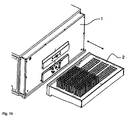
- the Fig. 1 a shows a schematic representation of a feeding and sorting device and the Fig. 1b shows a first schematic representation of a base unit 1 and a gate valve unit 2 of the feeding and sorting device Fig. 1 a in disassembled state.
- the base unit 1 is stationary and the gate valve unit 2 can be selected and changed product-specific according to the requirements of the supplied and sorted tablets, capsules, dragees or the like.
- the Fig. 2 shows a second schematic representation of the base unit 1 and a format unit 9, which includes the Absperrschieberussi 2, filling tube 10 and Guzzo 8, wherein the format unit 8 according to the requirements of the supplied and sorting tablets, capsules, dragees or the like selected product-specific and changed can be.
- the base unit 1 has a suspension device 11, so that the format unit 9 can be separated from the base unit 1 without tools.
- the tablets to be sorted and to be supplied and the like are passed on a hopper via a vibration unit in a sorting plate 12, where they are sorted by up and down movements in the filling tube 10.
- the tablets are aligned and then separated via the gate valve unit 2.
- the tablets are placed in a mold sheet under the feed.
- the gate valve unit 2 has slide guides 3 and, for example, two gate valves 4a and 4b arranged one above the other.
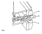
- the Fig. 4 shows in an enlarged view for the embodiment of Fig. 3 in that a means 5 for generating a magnetic field (hereinafter referred to as magnet 5), in particular a permanent magnet or an electromagnet, is mounted on a magnetic receptacle 6 on the base unit 1 and the coupling 7 for the magnet 5 on the gate valve plate 4a of the gate valve unit 2.
- magnet 5 a means 5 for generating a magnetic field
- the tablets or the like are passed from a hopper via a vibration unit in the sorting device, where they are sorted by up and down movements in the filling tube.
- the tablets are aligned and then separated via the Absperrschieberussi 2 so that they can be fed to the blister packs ordered.
- the gate valves 4a and 4b are moved back and forth in opposite directions, this movement being transmitted directly from the base unit 1 to gate valves 4a and 4b.
- the gate valves 4a and 4b are guided in the slide guides 3 and thus perform a linear movement.
- the gate valve unit 2 When switching the feeding and sorting device to a new format of the tablets, the gate valve unit 2 must be disconnected from the basic unit 1 or coupled to it. Like in the Fig. 4 is shown, the magnetic coupling and thus the connection between the base unit 1 and gate valve unit 2 via a magnet 5 on a magnet holder 6 and the clutch 7 is effected. Because of the solid Magnetic coupling can thus be transferred to the movements for the gate valves on the magnet.
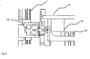
- the format unit 9 can be secured in operation against unwanted movements relative to the base unit 1 by the format unit 9 is stretched onto the suspension device 11 of the base unit 1 with a pneumatic cylinder 13.
- a recess 14 is provided, in which the pneumatic cylinder 13 can engage.
Landscapes
- Engineering & Computer Science (AREA)
- Mechanical Engineering (AREA)
- Basic Packing Technique (AREA)
Claims (9)
- Dispositif d'alimentation et de tri pour des comprimés, gélules, dragées ou analogues, en particulier sur des machines de thermoformage, comprenant une unité de base (1) et une unité de tiroir d'arrêt (2), qui présente au moins une glissière de tiroir (3) et une plaque de tiroir d'arrêt (4a, 4b) mobile dans la glissière (3), caractérisé en ce que l'unité de base (1) et l'unité de tiroir d'arrêt (2) sont configurées avec des aimants (5), en particulier des aimants permanents ou des électroaimants, sur des logements d'aimants (6) et des accouplements (7) pour les aimants (5) de telle sorte que l'unité de tiroir d'arrêt (2) est assemblée de façon amovible avec l'unité de base (1) par l'intermédiaire des aimants (5) et des accouplements (7), de sorte qu'une transmission du mouvement de l'unité de base (1) à l'unité de tiroir d'arrêt (2), avec sa plaque de tiroir (4a, 4b), est réalisable par l'intermédiaire des aimants (5) et des accouplements (7).
- Dispositif d'alimentation et de tri suivant la revendication 1, caractérisé en ce que les aimants (5) sont disposés sur l'unité de base (1) et les accouplements (7) sont disposés sur l'unité de tiroir d'arrêt (2).
- Dispositif d'alimentation et de tri suivant la revendication 1, caractérisé en ce que les aimants (5) sont disposés sur l'unité de tiroir d'arrêt (2) et les accouplements (7) sont disposés sur l'unité de base (1).
- Dispositif d'alimentation et de tri suivant la revendication 1, caractérisé en ce que les aimants (5) sont disposés aussi bien sur l'unité de base (1) que sur l'unité de tiroir d'arrêt (2) et les accouplements (7) sont disposés aussi bien sur l'unité de tiroir d'arrêt (2) que sur l'unité de base (1).
- Dispositif d'alimentation et de tri suivant l'une des revendications précédentes, caractérisé en ce que l'unité de tiroir d'arrêt (2) présente deux plaques de tiroir d'arrêt (4a, 4b) superposées, les logements d'aimants (6) et les accouplements (7) pour les aimants (5) étant disposés en déport de telle sorte que les plaques de tiroir d'arrêt (4a, 4b) sont mobiles en sens contraire.
- Dispositif d'alimentation et de tri suivant l'une des revendications précédentes, caractérisé par une unité de formatage (9) et par le fait que l'unité de base (1) présente un dispositif d'accrochage (11), l'unité de formatage (9) comprenant l'unité de tiroir d'arrêt (2), des tubes de remplissage (10) et des sabots de remplissage (8), et le dispositif d'accrochage (11) et l'unité de formatage (9) étant configurés de telle sorte que l'unité de formatage (9) est séparable sans outils de l'unité de base (1).
- Dispositif d'alimentation et de tri suivant la revendication 6, caractérisé en ce que l'unité de formatage (9) présente un évidement (14), et que l'unité de formatage (9) peut être fixée par l'intermédiaire d'un cylindre pneumatique (13) sur le dispositif d'accrochage (11).
- Unité de base (1) destinée à un dispositif d'alimentation et de tri pour des comprimés, gélules, dragées ou analogues, en particulier sur des machines de thermoformage, caractérisée en ce que l'unité de base (1) est configurée pour un assemblage amovible avec une unité de tiroir d'arrêt (2) et pour une transmission de mouvement de l'unité de base (1) à l'unité de tiroir d'arrêt (2) par couplage magnétique par l'intermédiaire d'aimants (5) sur des logements d'aimants (6) et accouplements (7) pour les aimants (5).
- Unité de tiroir d'arrêt (2) pour un dispositif d'alimentation et de tri destiné à des comprimés, gélules, dragées ou analogues, en particulier sur des machines de thermoformage, caractérisée en ce que l'unité de tiroir d'arrêt (2) est configurée pour un assemblage amovible de l'unité de base (1) avec une unité de tiroir d'arrêt (2) et pour une transmission de mouvement de l'unité de base (1) à l'unité de tiroir d'arrêt (2) par couplage magnétique par l'intermédiaire d'aimants (5) sur des logements d'aimants (6) et accouplements (7) pour les aimants (5).
Priority Applications (3)
| Application Number | Priority Date | Filing Date | Title |
|---|---|---|---|
| EP08007415A EP2110323B1 (fr) | 2008-04-16 | 2008-04-16 | Dispositif d'alimentation et de tri pour machines d'emballage |
| DE502008002130T DE502008002130D1 (de) | 2008-04-16 | 2008-04-16 | Zuführ- und Sortiervorrichtung für Verpackungsmaschinen |
| US12/424,283 US20090261025A1 (en) | 2008-04-16 | 2009-04-15 | Feed and sorting device for packaging machines |
Applications Claiming Priority (1)
| Application Number | Priority Date | Filing Date | Title |
|---|---|---|---|
| EP08007415A EP2110323B1 (fr) | 2008-04-16 | 2008-04-16 | Dispositif d'alimentation et de tri pour machines d'emballage |
Publications (2)
| Publication Number | Publication Date |
|---|---|
| EP2110323A1 EP2110323A1 (fr) | 2009-10-21 |
| EP2110323B1 true EP2110323B1 (fr) | 2010-12-29 |
Family
ID=39768661
Family Applications (1)
| Application Number | Title | Priority Date | Filing Date |
|---|---|---|---|
| EP08007415A Not-in-force EP2110323B1 (fr) | 2008-04-16 | 2008-04-16 | Dispositif d'alimentation et de tri pour machines d'emballage |
Country Status (3)
| Country | Link |
|---|---|
| US (1) | US20090261025A1 (fr) |
| EP (1) | EP2110323B1 (fr) |
| DE (1) | DE502008002130D1 (fr) |
Cited By (1)
| Publication number | Priority date | Publication date | Assignee | Title |
|---|---|---|---|---|
| CN110785357A (zh) * | 2017-06-22 | 2020-02-11 | 伊丽莎白欧洲公司 | 用于将片剂分配/分派在泡罩包装式包装类型的机器的包装带的泡罩袋中的可重构设备 |
Families Citing this family (1)
| Publication number | Priority date | Publication date | Assignee | Title |
|---|---|---|---|---|
| EP4705190A1 (fr) * | 2023-05-03 | 2026-03-11 | Daniel Hiddink | Dispositif pour l'emballage sous blister de pilules, comprimés, capsules et analogues et procédé correspondant |
Family Cites Families (11)
| Publication number | Priority date | Publication date | Assignee | Title |
|---|---|---|---|---|
| US3545164A (en) * | 1968-08-22 | 1970-12-08 | Warnaco Inc | Apparatus and method for filling packaging receptacles |
| DE2411300C2 (de) * | 1974-03-09 | 1976-04-29 | G. Siempelkamp & Co, 4150Krefeld | Einrichtung zum Zusammenlegen einer unteren Decklage, einer Mittellage und einer oberen Decklage zu einem Stapel im Zuge der Herstellung von vergüteten Trägerplatten und dgl |
| DE3541672A1 (de) * | 1985-11-26 | 1987-05-27 | Uhlmann Maschf Josef | Vorrichtung an verpackungsmaschinen zum geordneten zufuehren und ablegen zu verpackender kleinteile, wie tabletten, kapseln, dragees oder dergl. |
| JP2544052B2 (ja) * | 1991-12-18 | 1996-10-16 | 日本エランコ株式会社 | 硬質ゼラチンカプセルへの錠剤充填装置 |
| DE29919756U1 (de) * | 1999-11-10 | 2001-03-22 | Electro-Mec (Reading) Ltd., Reading | Verpackungsvorrichtung |
| IT1311419B1 (it) * | 1999-12-07 | 2002-03-12 | Ima Spa | Dispositivo per l'alimentazione di articoli ad un sottostante nastroalveolato. |
| US6581356B2 (en) * | 2001-09-24 | 2003-06-24 | Jun H. Kim | Tablet dispensing and packaging system |
| US6935828B2 (en) * | 2002-07-17 | 2005-08-30 | Transfer Engineering And Manufacturing, Inc. | Wafer load lock and magnetically coupled linear delivery system |
| DE10236626A1 (de) * | 2002-08-09 | 2004-02-19 | Siemens Ag | Vorrichtung zum selektiven Bewegen von Haltevorrichtungen und Bestückkopf zum Transportieren von Bauelementen |
| DE102005049882B3 (de) * | 2005-10-17 | 2007-02-01 | Uhlmann Pac-Systeme Gmbh & Co. Kg. | Vorrichtung zum geordneten Zuführen und Ablegen zu verpackender Kleinteile in die Näpfe einer Folienbahn |
| US7389632B2 (en) * | 2006-06-10 | 2008-06-24 | Uhlmann Pac-Systeme Gmbh & Co. Kg | Apparatus for distributing small objects in a fill station |
-
2008
- 2008-04-16 EP EP08007415A patent/EP2110323B1/fr not_active Not-in-force
- 2008-04-16 DE DE502008002130T patent/DE502008002130D1/de active Active
-
2009
- 2009-04-15 US US12/424,283 patent/US20090261025A1/en not_active Abandoned
Cited By (2)
| Publication number | Priority date | Publication date | Assignee | Title |
|---|---|---|---|---|
| CN110785357A (zh) * | 2017-06-22 | 2020-02-11 | 伊丽莎白欧洲公司 | 用于将片剂分配/分派在泡罩包装式包装类型的机器的包装带的泡罩袋中的可重构设备 |
| CN110785357B (zh) * | 2017-06-22 | 2021-07-13 | 伊丽莎白欧洲公司 | 用于将片剂分配/分派在泡罩包装式包装类型的机器的包装带的泡罩袋中的可重构设备 |
Also Published As
| Publication number | Publication date |
|---|---|
| US20090261025A1 (en) | 2009-10-22 |
| DE502008002130D1 (de) | 2011-02-10 |
| EP2110323A1 (fr) | 2009-10-21 |
Similar Documents
| Publication | Publication Date | Title |
|---|---|---|
| EP2508259B1 (fr) | Dispositif de pipetage | |
| EP2845714A1 (fr) | Dispositif et procédé destinés au chauffage d'ébauches en plastique avec montage ou démontage simultané d'éléments de chauffage et d'éléments de blindage | |
| DE102014114091B3 (de) | Dosierstation für eine Kapselfüllmaschine und Kapselfüllmaschine | |
| EP2207656B1 (fr) | Dispositif de formation de manchons sur des tubes en matiere synthetique | |
| DE4310953A1 (de) | Einpresseinrichtung zum Einpressen von Fügeteilen | |
| DE102010051239A1 (de) | Bearbeitungsstation für eine Stanzmaschine und Verfahren zur Probebogenauslage | |
| EP2110323B1 (fr) | Dispositif d'alimentation et de tri pour machines d'emballage | |
| EP3650213B1 (fr) | Presse à comprimés et procédé de fabrication d'un comprimé | |
| EP2925613A1 (fr) | Machine d'emballage comprenant un système de changement d'outil | |
| WO2010072411A1 (fr) | Unité de chargement et de déchargement de tôles avec un porte-outil pour machines d'usinage de la tôle | |
| DE19731344B4 (de) | System zum Zuführen von Verbindungselementen an einen Stanzkopf | |
| EP2110324B1 (fr) | Unité de verrouillage d'un dispositif d'alimentation et de tri pour machines d'emballage | |
| WO2020053187A1 (fr) | Dispositif comprenant un premier et un deuxième robot et son procédé de fonctionnement | |
| WO2001038070A1 (fr) | Dispositif et procede permettant de realiser un mouvement lineaire en deux temps | |
| DE102011077308A1 (de) | Biegemaschine und Biegewerkzeug | |
| DE202009010128U1 (de) | Stanzvorrichtung | |
| DE102005044759B4 (de) | Vorrichtung zum Herstellen eines Formteils | |
| EP1878558B1 (fr) | Machine de thermoformage | |
| DE19749633B4 (de) | Fertigungs- und/oder Montagevorrichtung | |
| EP4031210B1 (fr) | Dispositif et procédé de fermeture de corps de seringue | |
| DE3703700C2 (de) | Stanzpresse mit einer automatischen Werkzeugwechselvorrichtung | |
| DE10062445C1 (de) | Verfahren und Vorrichtung zum Lochen von Blättern | |
| DE202009008413U1 (de) | Werkzeugsystem für eine Umformpresse | |
| AT522269B1 (de) | Formgebungsmaschine und/oder Baugruppe für eine Formgebungsmaschine | |
| DE202024101855U1 (de) | Verpackungseinrichtung |
Legal Events
| Date | Code | Title | Description |
|---|---|---|---|
| PUAI | Public reference made under article 153(3) epc to a published international application that has entered the european phase |
Free format text: ORIGINAL CODE: 0009012 |
|
| 17P | Request for examination filed |
Effective date: 20081107 |
|
| AK | Designated contracting states |
Kind code of ref document: A1 Designated state(s): AT BE BG CH CY CZ DE DK EE ES FI FR GB GR HR HU IE IS IT LI LT LU LV MC MT NL NO PL PT RO SE SI SK TR |
|
| AX | Request for extension of the european patent |
Extension state: AL BA MK RS |
|
| AKX | Designation fees paid |
Designated state(s): DE FR GB IE IT SE |
|
| GRAP | Despatch of communication of intention to grant a patent |
Free format text: ORIGINAL CODE: EPIDOSNIGR1 |
|
| GRAS | Grant fee paid |
Free format text: ORIGINAL CODE: EPIDOSNIGR3 |
|
| GRAA | (expected) grant |
Free format text: ORIGINAL CODE: 0009210 |
|
| AK | Designated contracting states |
Kind code of ref document: B1 Designated state(s): DE FR GB IE IT SE |
|
| REG | Reference to a national code |
Ref country code: GB Ref legal event code: FG4D Free format text: NOT ENGLISH |
|
| REG | Reference to a national code |
Ref country code: IE Ref legal event code: FG4D Free format text: LANGUAGE OF EP DOCUMENT: GERMAN |
|
| REF | Corresponds to: |
Ref document number: 502008002130 Country of ref document: DE Date of ref document: 20110210 Kind code of ref document: P |
|
| REG | Reference to a national code |
Ref country code: DE Ref legal event code: R096 Ref document number: 502008002130 Country of ref document: DE Effective date: 20110210 |
|
| PG25 | Lapsed in a contracting state [announced via postgrant information from national office to epo] |
Ref country code: SE Free format text: LAPSE BECAUSE OF FAILURE TO SUBMIT A TRANSLATION OF THE DESCRIPTION OR TO PAY THE FEE WITHIN THE PRESCRIBED TIME-LIMIT Effective date: 20101229 |
|
| PLBE | No opposition filed within time limit |
Free format text: ORIGINAL CODE: 0009261 |
|
| STAA | Information on the status of an ep patent application or granted ep patent |
Free format text: STATUS: NO OPPOSITION FILED WITHIN TIME LIMIT |
|
| 26N | No opposition filed |
Effective date: 20110930 |
|
| REG | Reference to a national code |
Ref country code: FR Ref legal event code: ST Effective date: 20111230 |
|
| REG | Reference to a national code |
Ref country code: DE Ref legal event code: R097 Ref document number: 502008002130 Country of ref document: DE Effective date: 20110930 |
|
| PG25 | Lapsed in a contracting state [announced via postgrant information from national office to epo] |
Ref country code: FR Free format text: LAPSE BECAUSE OF NON-PAYMENT OF DUE FEES Effective date: 20110502 |
|
| REG | Reference to a national code |
Ref country code: DE Ref legal event code: R082 Ref document number: 502008002130 Country of ref document: DE Representative=s name: KROHER . STROBEL RECHTS- UND PATENTANWAELTE PA, DE Ref country code: DE Ref legal event code: R081 Ref document number: 502008002130 Country of ref document: DE Owner name: UHLMANN PAC-SYSTEME GMBH & CO. KG, DE Free format text: FORMER OWNER: UHLMANN PAC-SYSTEME GMBH & CO KG, 88471 LAUPHEIM, DE Ref country code: DE Ref legal event code: R082 Ref document number: 502008002130 Country of ref document: DE Representative=s name: KROHER STROBEL RECHTS- UND PATENTANWAELTE PART, DE |
|
| REG | Reference to a national code |
Ref country code: DE Ref legal event code: R082 Ref document number: 502008002130 Country of ref document: DE Representative=s name: KROHER STROBEL RECHTS- UND PATENTANWAELTE PART, DE |
|
| PGFP | Annual fee paid to national office [announced via postgrant information from national office to epo] |
Ref country code: IT Payment date: 20230428 Year of fee payment: 16 Ref country code: IE Payment date: 20230420 Year of fee payment: 16 Ref country code: DE Payment date: 20230427 Year of fee payment: 16 |
|
| PGFP | Annual fee paid to national office [announced via postgrant information from national office to epo] |
Ref country code: GB Payment date: 20230420 Year of fee payment: 16 |
|
| REG | Reference to a national code |
Ref country code: DE Ref legal event code: R119 Ref document number: 502008002130 Country of ref document: DE |
|
| GBPC | Gb: european patent ceased through non-payment of renewal fee |
Effective date: 20240416 |
|
| PG25 | Lapsed in a contracting state [announced via postgrant information from national office to epo] |
Ref country code: DE Free format text: LAPSE BECAUSE OF NON-PAYMENT OF DUE FEES Effective date: 20241105 |
|
| PG25 | Lapsed in a contracting state [announced via postgrant information from national office to epo] |
Ref country code: GB Free format text: LAPSE BECAUSE OF NON-PAYMENT OF DUE FEES Effective date: 20240416 |
|
| PG25 | Lapsed in a contracting state [announced via postgrant information from national office to epo] |
Ref country code: GB Free format text: LAPSE BECAUSE OF NON-PAYMENT OF DUE FEES Effective date: 20240416 Ref country code: DE Free format text: LAPSE BECAUSE OF NON-PAYMENT OF DUE FEES Effective date: 20241105 |
|
| PG25 | Lapsed in a contracting state [announced via postgrant information from national office to epo] |
Ref country code: IE Free format text: LAPSE BECAUSE OF NON-PAYMENT OF DUE FEES Effective date: 20240416 |
|
| PG25 | Lapsed in a contracting state [announced via postgrant information from national office to epo] |
Ref country code: IT Free format text: LAPSE BECAUSE OF NON-PAYMENT OF DUE FEES Effective date: 20240416 |