EP1878558B1 - Machine de thermoformage - Google Patents
Machine de thermoformage Download PDFInfo
- Publication number
- EP1878558B1 EP1878558B1 EP07112191A EP07112191A EP1878558B1 EP 1878558 B1 EP1878558 B1 EP 1878558B1 EP 07112191 A EP07112191 A EP 07112191A EP 07112191 A EP07112191 A EP 07112191A EP 1878558 B1 EP1878558 B1 EP 1878558B1
- Authority
- EP
- European Patent Office
- Prior art keywords
- clamping
- plate
- thermoforming machine
- upper plate
- frame
- Prior art date
- Legal status (The legal status is an assumption and is not a legal conclusion. Google has not performed a legal analysis and makes no representation as to the accuracy of the status listed.)
- Not-in-force
Links
Images

Classifications
-
- B—PERFORMING OPERATIONS; TRANSPORTING
- B29—WORKING OF PLASTICS; WORKING OF SUBSTANCES IN A PLASTIC STATE IN GENERAL
- B29C—SHAPING OR JOINING OF PLASTICS; SHAPING OF MATERIAL IN A PLASTIC STATE, NOT OTHERWISE PROVIDED FOR; AFTER-TREATMENT OF THE SHAPED PRODUCTS, e.g. REPAIRING
- B29C51/00—Shaping by thermoforming, i.e. shaping sheets or sheet like preforms after heating, e.g. shaping sheets in matched moulds or by deep-drawing; Apparatus therefor
- B29C51/26—Component parts, details or accessories; Auxiliary operations
- B29C51/30—Moulds
- B29C51/38—Opening, closing or clamping means
Definitions
- the present invention relates to a thermoforming machine.
- Thermoforming machines generally serve to deform a flat product from a material which, in the heated state, is deformable by means of mold sections with cavities arranged therein, wherein an internal shaping of each cavity corresponds to an external shaping of an article to be formed in the cavity.
- Thermoforming machines are well known and include, for example, material loaders, heaters, shapers, discharge devices, etc.
- the technology of thermoforming thermoplastic or thermosetting materials of relatively large dimensions has evolved in response to increasing needs in various industries.
- thermoforming machine which as a “twin sheet thermoformer”, that is, as a thermoforming machine, in which two parts are manufactured simultaneously, is formed.
- the thermoforming machine in this case has an upper and a lower plate, which are height adjustable relative to a frame by means of motors.
- hydraulic pistons On the upper plate hydraulic pistons are mounted, which can be connected via connecting elements by means of a positive connection firmly with the lower plate.
- the piston rods are introduced into associated counter-elements and locked with these form-fitting.
- the publication EP 0919356 A2 describes a vacuum forming machine for forming moldings.
- the vacuum forming machine has a lower die mounted in a lower frame-shaped machine structure and an upper die mounted in an upper frame-shaped machine structure.
- the vacuum forming machine further has at least one core pull locking cylinder which is secured to the lower and upper frame-shaped machine structure and is lockable with an associated locking device which is attached to the other frame-shaped machine structure.
- thermoforming machine which ensures a more appropriate coupling of the lower and the upper plate for a contraction of the same to each other.
- thermoforming machine with the features of claim 1.
- thermoforming machine comprises a frame; a first plate and a second plate for receiving mold sections, at least one of the plates being adjustable relative to the frame; Drive means for adjusting the plates relative to each other; and a pulling mechanism for pulling one of the plates towards the other plate, the pulling mechanism having at least one pulling means attached to one of the plates with a drawbar which, when the two plates are adjusted relative to each other, has an associated clamping means attached to the other of the plates can be clamped for a non-positive coupling.
- the present invention over the above approach has the advantage that when exceeding a predetermined maximum value for the tensile force acting on the corresponding plate damage to the tension mechanism or the connecting elements for a coupling of the two plates does not occur because due to inventive non-positive clamping connection, the two mutually frictionally jammed elements relative movements to each other Run, that is, when exceeding a predetermined maximum value for the tensile force acting on the corresponding plate slipping of the drawbar, such as a piston rod, is ensured by the associated clamping device without the corresponding elements of the pulling mechanism are destroyed or damaged.
- the thermoforming machine has an upper plate, which is uniformly adjustable vertically by a drive motor and associated spindles, in particular ball screws, vertically to the frame.
- the thermoforming machine also has a lower plate arranged below the upper plate, which is preferably also vertically adjustable relative to the frame by means of a further drive motor with associated spindles, in particular ball screw spindles.
- the upper and lower plate can be adjusted in height depending on the mold sections used in each case and brought to a suitable height to each other.
- the upper plate and / or the lower plate are preferably also adjustable horizontally to the frame by means of associated adjusting elements, so that the respectively used mold sections of the upper and lower plates can be adjusted to one another.
- the piston devices or the respective piston rods are associated with the respective ones Aligned clamping devices that when an adjustment of the upper and lower plate to each other to the piston rod of a piston device of the upper plate enters an associated clamping device of the lower plate and each frictionally clamped with such a clamping force that when exceeding a predetermined tensile force, the piston rod from the associated Slip out clamping cylinders.
- the lower plate pulled in the direction of the upper plate with a predetermined tensile force and a deformation of the material provided by ensures the coupled with the plates mold sections.
- the clamping devices are each designed as hydraulic or pneumatic clamping cylinder, which each have a clamping bush with an outer cone and a clamping sleeve with an inner cone, wherein the clamping bush is axially fixed in a housing of the clamping device and radially movable and the clamping sleeve is axially guided in the housing and for clamping a recorded in the clamping device piston rod in the axial direction on the clamping axis by means of pneumatic or hydraulic force is pushed.
- thermoforming machine preferably has an upper heater provided below the upper plate and a lower heater provided above the lower plate, at least one of the heaters being vertically adjustable to the frame by means of an associated adjusting device and a plurality of independent heating sections , preferably two juxtaposed heating sections comprises.
- a thermoforming machine 1 has a frame 2 for supporting the individual components of the thermoforming machine 1.
- the thermoforming machine 1 comprises an upper plate 3, to which predetermined mold sections are attached for shaping the material to be thermoformed.
- the upper plate 3 is height adjustable by means of an associated drive motor and associated ball screws 4, preferably vertically to the frame 2.
- the top plate 3 if necessary also be horizontally mounted to the frame 2 by means of suitable drives and adjusting adjustable on the frame 2.
- ball screws 4 are provided, which are arranged rectangular with respect to the upper plate 3 and ensure a uniform height adjustment of the upper plate 3.
- thermoforming machine 1 also preferably has a plurality of hydraulic cylinders 5, which are fixedly coupled to the upper plate 3.
- hydraulic cylinders 4 for example, predetermined and well-known displacement measuring systems can be integrated for detecting the adjustment.
- the respective piston rods 6 of the individual hydraulic cylinders 5 protrude in a state in which the thermoforming machine 1 has moved apart Fig. 1 is exemplified, below the upper plate 3 directed downward.
- thermoforming machine 1 includes referring to FIG Fig. 1 a lower plate 7, on which analogous to the upper plate 3 predetermined mold sections are attached, which correspond to the mold sections of the upper plate 3 for shaping the thermo-forming material.
- the lower plate 7 is according to the present embodiment via an associated drive and associated ball screws 8 also preferably vertically adjustable relative to the frame 2, so that the upper plate 3 and the lower plate 3 relative to each other and directed towards each other depending on the mold sections used or are adjustable depending on the shaped workpiece to be produced.
- a plurality of clamping cylinders 9 are preferably fixedly mounted so that each piston rod 6 and each hydraulic cylinder 5 of the upper plate an opposite Clamping cylinder 9 is assigned suitable.
- the lower plate 7 can preferably also be moved horizontally by means of associated drives and adjusting elements relative to the frame 2 in order to carry out a desired thermoforming process in connection with the correspondingly aligned upper plate 3. It is also conceivable that only one of the plates 3, 7 is mounted horizontally adjustable.
- the thermoforming machine 1 has a heating mechanism, which has, for example, two upper heaters 10, 11, which are also adjustable in height relative to the frame 2 by means of suitable drives and adjusting elements according to the respective thermoforming process to be performed.
- a heating mechanism which has, for example, two upper heaters 10, 11, which are also adjustable in height relative to the frame 2 by means of suitable drives and adjusting elements according to the respective thermoforming process to be performed.
- Below the upper heating device 10, 11 preferably two lower heating devices 12, 13 are provided, which are also adjustable in height relative to the frame 2 by means of suitable drives and adjusting elements.
- the upper heaters 10, 11 and the lower heaters 12, 13 are provided for heating the thermoforming material prior to the thermoforming process.
- thermoforming machine 1 by means of the exemplary thermoforming machine 1 of the present embodiment explained in more detail.
- the in Fig. 1 illustrated state of the thermoforming machine 1 represents the machine state before the thermoforming process.
- the upper plate 3 and the lower plate 7 is moved toward each other by means of the above-described drives and adjusting elements, for example the upper plate 3 is moved downwards in the direction of the lower plate 7 and / or the lower plate 7 upwards in the direction of the upper plate 3.
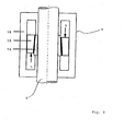
- FIG. 2 Due to this relative movement of the upper plate 3 and the lower plate 7, the individual piston rods 6 of the hydraulic cylinder 5 of the upper plate 3 are inserted into the respectively associated and correspondingly below the hydraulic cylinder 5 arranged clamping cylinder 9 of the lower plate 7, as in Fig. 2 is schematically illustrated in a partial view.
- the left half of the Fig. 2 illustrates the clamping cylinder 9 while in a released state L and the right half of Fig. 2 the clamping cylinder 9 in a clamped state K.
- Each clamping cylinder 9 can steplessly clamp an associated piston rod 6 without changing its position, and furthermore each clamping cylinder 9 can absorb axial forces in both directions.
- the clamping cylinder 9 are activated or deactivated by applying force, in particular by hydraulic application of force. It is obvious to a person skilled in the art that pneumatic application of force is also possible.
- the clamping cylinders 9 preferably each consist of a clamping bush 14 with an outer cone and a clamping sleeve 15 with an inner cone, as in Fig. 2 is illustrated.
- the clamping bush 14 is advantageously guided in a housing 16 of the clamping cylinder 9 and is pressed for clamping the associated piston rod 6 in the axial direction via the clamping bush 14.
- the necessary clamping force is accomplished for example by the above-mentioned hydraulic pressurization.
- reference numeral K denotes a clamping force for pressing the collet 15 via the clamp bushing 14 for jamming the inserted piston rod 6.
- reference L in Fi. 2 a force for releasing the jamming, so that the inserted piston rod 6 can slide smoothly in the clamping cylinder 9.
- the hydraulic cylinders 5 of the upper plate 3 are driven so that a tensile force is applied to the lower plate 7 having the clamping cylinders 9 with a predetermined size.
- the lower plate 7 is pulled against the upper plate 3 to provide the necessary deforming force for thermoforming the heated material by means of the provided mold sections of the upper plate 3 and the lower plate 7 with a predetermined tensile force.
- Due to the above-described frictional connection between the piston rods 6 and the associated clamping cylinders 9 takes place when exceeding a predetermined maximum value of the tensile force, a sliding movement of the inserted piston rods 6 relative to the associated clamping cylinders 9.
- the force exerted on the lower plate 7 tensile force is released by corresponding drives the hydraulic cylinder 5, the upper plate 3 and the lower plate 7 by means of the corresponding drives and actuators moved away from each other and removed the thermoformed workpiece.
Landscapes
- Engineering & Computer Science (AREA)
- Mechanical Engineering (AREA)
- Blow-Moulding Or Thermoforming Of Plastics Or The Like (AREA)
- Moulds For Moulding Plastics Or The Like (AREA)
- Heating, Cooling, Or Curing Plastics Or The Like In General (AREA)
Claims (10)
- Presse de thermoformage (1) comprenant :- un bâti (2) ;- une première plaque (3) et une seconde plaque (7) permettant de recevoir des sections de moule, au moins une des plaques (3 ; 7) pouvant être déplacée par rapport au bâti (2),- et des moyens d'entraînement (4 ; 8) permettant de déplacer les plaques (3 ; 7) l'une par rapport à l'autre, un mécanisme de traction (5, 6 ; 9) permettant de tirer une des plaques (7) en direction de l'autre plaque (3) étant prévu, le mécanisme de traction (5, 6 ; 9) présentant au moins un dispositif de traction (5) fixé à une des plaques (3) et doté d'une tige de traction (6) laquelle peut, lors du déplacement des deux plaques (3 ; 7) l'une par rapport à l'autre, être serrée dans un dispositif de serrage (9) associé, fixé à l'autre des plaques (7), pour former un accouplement,caractérisée en ce que
l'accouplement est à force et en ce que la première plaque (3) est conçue comme une plaque supérieure (3) qui peut être déplacée verticalement par rapport au bâti (2) à l'aide d'un moteur d'entraînement et de plusieurs broches pour assurer un déplacement uniforme de la plaque supérieure (3) verticalement par rapport au bâti (2). - Presse de thermoformage selon la revendication 1, caractérisée en ce que les broches (4) sont des broches filetées à billes.
- Presse de thermoformage selon au moins une des revendications précédentes, caractérisée en ce que la seconde plaque (7) est conçue comme une plaque inférieure (7) disposée au-dessous de la plaque supérieure (3) et qui peut être déplacée verticalement par rapport au bâti (2) à l'aide de seconds moyens d'entraînement (8).
- Presse de thermoformage selon la revendication 3, caractérisée en ce que les seconds moyens d'entraînement présentent un moteur d'entraînement et plusieurs broches (8), en particulier des broches filetées à billes, pour assurer un déplacement uniforme de la plaque inférieure (7) verticalement par rapport au bâti (2).
- Presse de thermoformage selon la revendication 3 ou 4, caractérisée en ce que la plaque supérieure (3) et/ou la plaque inférieure (7) peuvent être déplacées horizontalement par rapport au bâti (2) à l'aide de moyens de déplacement associés.
- Presse de thermoformage selon au moins une des revendications 3 à 5, caractérisée en ce que plusieurs vérins hydrauliques (5), de préférence quatre, sont fixés à la plaque supérieure (3) en tant que dispositifs de traction et des dispositifs de serrage respectivement associés, ayant la forme de vérins de serrage (9), sont fixés à la plaque inférieure (7).
- Presse de thermoformage selon la revendication 6, caractérisée en ce que chaque tige de piston (6) d'un vérin hydraulique (5) de la plaque supérieure (3) peut, lors du déplacement des plaques (3, 7) l'une envers l'autre, être introduite dans un vérin de serrage (9) respectivement associé de la plaque inférieure (7) et peut dans chaque cas être serrée par adhérence avec une force de serrage telle qu'en cas de dépassement d'une force de traction prédéfinie, les tiges de piston (6) glissent hors des vérins de serrage (9) associés.
- Presse de thermoformage selon au moins une des revendications 3 à 7, caractérisée en ce qu'en cas d'actionnement des dispositifs de traction (5) de la plaque supérieure (3), la plaque inférieure (7) accouplée par adhérence via les dispositifs de serrage (9) peut être tirée en direction de la plaque supérieure (3) à une force de traction prédéfinie.
- Presse de thermoformage selon au moins une des revendications précédentes, caractérisée en ce que les dispositifs de serrage (9) sont chacun conçus sous forme de vérins de serrage hydrauliques ou pneumatiques (9), qui présentent chacun une douille de serrage (14) dotée d'un cône extérieur et une douille de serrage (15) dotée d'un cône intérieur, la douille de serrage (14) étant à chaque fois fixée axialement et à mobilité radiale dans un carter (16) du dispositif de serrage associé (9), et la douille de serrage respective (15) étant guidée axialement dans le carter (16) et, pour le serrage d'une tige de piston (6) associée, logée dans le dispositif de serrage respectif (9), pouvant être poussée dans le sens axial par la douille de serrage (14) respectivement associée avec une sollicitation en force prédéfinie.
- Presse de thermoformage selon au moins une des revendications 3 à 9, caractérisée en ce que la presse de thermoformage (1) présente au moins un dispositif de chauffage supérieur (10, 11), qui est prévu au-dessous de la plaque supérieure (3), et au moins un dispositif de chauffage inférieur (12, 13), qui est prévu au-dessus de la plaque inférieure (7), au moins un des deux dispositifs de chauffage (10, 11 ; 12, 13) pouvant être déplacé verticalement par rapport au bâti (2) à l'aide d'un dispositif de déplacement associé et possédant plusieurs sections indépendantes, de préférence deux sections de chauffage (10, 11 ; 12, 13) disposées l'une à côté de l'autre.
Priority Applications (1)
| Application Number | Priority Date | Filing Date | Title |
|---|---|---|---|
| PL07112191T PL1878558T3 (pl) | 2006-07-14 | 2007-07-10 | Termoformierka |
Applications Claiming Priority (1)
| Application Number | Priority Date | Filing Date | Title |
|---|---|---|---|
| DE102006032862A DE102006032862A1 (de) | 2006-07-14 | 2006-07-14 | Thermoformmaschine |
Publications (3)
| Publication Number | Publication Date |
|---|---|
| EP1878558A2 EP1878558A2 (fr) | 2008-01-16 |
| EP1878558A3 EP1878558A3 (fr) | 2008-05-28 |
| EP1878558B1 true EP1878558B1 (fr) | 2011-04-20 |
Family
ID=38537649
Family Applications (1)
| Application Number | Title | Priority Date | Filing Date |
|---|---|---|---|
| EP07112191A Not-in-force EP1878558B1 (fr) | 2006-07-14 | 2007-07-10 | Machine de thermoformage |
Country Status (6)
| Country | Link |
|---|---|
| US (1) | US7540739B2 (fr) |
| EP (1) | EP1878558B1 (fr) |
| JP (1) | JP4975537B2 (fr) |
| AT (1) | ATE506170T1 (fr) |
| DE (2) | DE102006032862A1 (fr) |
| PL (1) | PL1878558T3 (fr) |
Families Citing this family (4)
| Publication number | Priority date | Publication date | Assignee | Title |
|---|---|---|---|---|
| GB201016930D0 (en) * | 2010-10-07 | 2010-11-24 | Ishida Europ Ltd | Lifting apparatus |
| ITMO20130291A1 (it) | 2013-10-16 | 2015-04-17 | Cms Spa | Apparato di formatura |
| US9963291B2 (en) | 2016-04-06 | 2018-05-08 | Altria Client Services Llc | Multicompartment capsules of a beverage forming apparatus and methods of making thereof |
| CN106493886A (zh) * | 2016-12-06 | 2017-03-15 | 青岛双星橡塑机械有限公司 | 轮胎下调模加力装置 |
Family Cites Families (23)
| Publication number | Priority date | Publication date | Assignee | Title |
|---|---|---|---|---|
| DE352466C (de) | 1922-04-27 | Frida Peters Geb Ney | Wandbrett, Platte oder Staender zum Aufhaengen oder Aufstellen von Gebrauchsgegenstaenden, wie Schluessel u. dgl. | |
| DE1306180U (fr) | ||||
| DE919356C (de) | 1952-06-29 | 1954-10-21 | Deutsche Bundesbahn | Erdschlussanzeiger |
| US3822579A (en) * | 1972-10-24 | 1974-07-09 | V Kononenko | High-speed counterstroke hammer |
| US3868209A (en) * | 1973-02-22 | 1975-02-25 | Koehring Co | Twin sheet thermoformer |
| US4435244A (en) * | 1981-10-28 | 1984-03-06 | The Continental Group, Inc. | Reciprocating clamp apparatus for thermoforming plastic containers |
| CH675096A5 (fr) * | 1987-04-09 | 1990-08-31 | Uniport Theodor Hirzel | |
| DE3825061A1 (de) * | 1988-07-23 | 1990-01-25 | Geiss Georg Maschf | Vakuumformmaschine |
| DE4033534C2 (de) | 1990-10-22 | 1999-06-10 | Illig Maschinenbau Adolf | Vorrichtung zum Formen, Stanzen und Stapeln von tiefgezogenen Teilen aus thermoplastischem Kunststoff |
| US5133655A (en) * | 1991-01-07 | 1992-07-28 | Husky Injection Molding Systems Ltd. | Friction clamp for injection molding machine |
| US5129817A (en) * | 1991-03-11 | 1992-07-14 | Husky Injection Molding Systems Ltd. | Gripper bushing assembly for an apparatus for making plastic articles |
| JPH05220749A (ja) * | 1992-02-07 | 1993-08-31 | Komatsu Ltd | 成形機の係止装置 |
| JPH0825067B2 (ja) * | 1992-08-27 | 1996-03-13 | 月島機械株式会社 | 型締め装置 |
| JP2860235B2 (ja) * | 1993-09-20 | 1999-02-24 | 株式会社ケンウッド | フィルム成形品の成形方法及びその装置 |
| JPH08243717A (ja) * | 1995-03-07 | 1996-09-24 | Ube Ind Ltd | 成形装置の型締装置 |
| DE29720910U1 (de) * | 1997-11-25 | 1998-02-12 | Georg Geiß Maschinenfabrik, 96145 Seßlach | Vakuumformmaschine zum Umformen von Formteilen |
| US6142763A (en) * | 1998-12-30 | 2000-11-07 | International Thermoforming Systems, Inc. | Thermal presses for forming articles from a web of thermoplastic material |
| DE19955519B4 (de) * | 1999-11-18 | 2005-03-17 | Siempelkamp Pressen Systeme Gmbh & Co | Umformpresse für die druckmedienbasierte Umformung von ebenen oder hohlen Werkstücken, insbes. für die Innenhochdruckumformung von hohlen Rohlingen, vorzugsweise Rohrabschnitten |
| DE10009405A1 (de) * | 2000-02-28 | 2001-08-30 | Kiefel Gmbh Paul | Vorrichtung zum Verformen von thermoplastischen Materialien |
| DE10152392C1 (de) * | 2001-10-24 | 2003-04-24 | Krauss Maffei Kunststofftech | Schließeinheit für eine Kunststoffformmaschine |
| US7150617B1 (en) * | 2003-11-17 | 2006-12-19 | The United States Of America As Represented By The Secretary Of The Navy | Multiple position press |
| DE102005039691A1 (de) * | 2005-04-19 | 2006-10-26 | Gerhard Schubert Gmbh | Pressantrieb |
| CN100488754C (zh) * | 2005-10-14 | 2009-05-20 | 鸿富锦精密工业(深圳)有限公司 | 热压成型机 |
-
2006
- 2006-07-14 DE DE102006032862A patent/DE102006032862A1/de not_active Ceased
-
2007
- 2007-06-27 US US11/823,347 patent/US7540739B2/en active Active
- 2007-07-06 JP JP2007178460A patent/JP4975537B2/ja not_active Expired - Fee Related
- 2007-07-10 AT AT07112191T patent/ATE506170T1/de active
- 2007-07-10 PL PL07112191T patent/PL1878558T3/pl unknown
- 2007-07-10 EP EP07112191A patent/EP1878558B1/fr not_active Not-in-force
- 2007-07-10 DE DE502007006976T patent/DE502007006976D1/de active Active
Also Published As
| Publication number | Publication date |
|---|---|
| JP4975537B2 (ja) | 2012-07-11 |
| EP1878558A2 (fr) | 2008-01-16 |
| US20080014298A1 (en) | 2008-01-17 |
| DE502007006976D1 (de) | 2011-06-01 |
| EP1878558A3 (fr) | 2008-05-28 |
| US7540739B2 (en) | 2009-06-02 |
| ATE506170T1 (de) | 2011-05-15 |
| PL1878558T3 (pl) | 2011-09-30 |
| JP2008018722A (ja) | 2008-01-31 |
| DE102006032862A1 (de) | 2008-01-17 |
Similar Documents
| Publication | Publication Date | Title |
|---|---|---|
| EP1878558B1 (fr) | Machine de thermoformage | |
| EP3710222B1 (fr) | Unité de fermeture de moule destinée à une machine de moulage par injection ainsi que procédé de blocage d'un élément de transmission de force | |
| EP3804959B1 (fr) | Dispositif d'emboutissage profond des corps d'emballage, par exemple des barquettes d'emballage, en feuille à emboutir | |
| EP1068060B1 (fr) | Unite de fermeture de moule pour une presse d'injection | |
| EP1237704A1 (fr) | Dispositif et procede permettant de realiser un mouvement lineaire en deux temps | |
| EP1802441B1 (fr) | Unite de fermeture destinee a une machine de moulage par injection comportant un moule a etages | |
| DE19925029B4 (de) | Verfahren zum Umformen und Vorrichtung zur Durchführung des Verfahrens | |
| EP1389161B1 (fr) | Dispositif d'entrainement servant notamment a entrainer une partie mobile de l'unite de fermeture ou de l'unite d'injection d'une presse d'injection de matieres plastiques | |
| EP1487626B1 (fr) | Dispositif de fermeture d'un moule a reglage en hauteur du moule, et procede permettant sa mise en action | |
| EP1764173A2 (fr) | Dispositif pour mouler de la poudre par pression | |
| AT522274B1 (de) | Gusswerkzeug-Spannvorrichtung | |
| DE10101837B4 (de) | Auswerfvorrichtung für eine Formmaschine | |
| EP1848577B1 (fr) | Machine de moulage par injection pour l'usinage de matieres plastiques | |
| AT412624B (de) | Spritzgiesseinrichtung | |
| AT522269B1 (de) | Formgebungsmaschine und/oder Baugruppe für eine Formgebungsmaschine | |
| AT526511B1 (de) | Schließeinheit sowie eine Formgebungsmaschine mit einer solchen Schließeinheit | |
| DE19925325C2 (de) | Schließeinheit für eine Maschine für die Verarbeitung von spritzgießfähigem Material | |
| DE3920690A1 (de) | Saeulenzieheinrichtung fuer spritzgiessmaschinen | |
| AT526987B1 (de) | Anordnung aus einer Formaufspannplatte für eine Formgebungsmaschine und zumindest einer Verriegelungsvorrichtung | |
| EP3584049B1 (fr) | Machine de moulage en plusieurs pièces | |
| EP4284623B1 (fr) | Moule pour former de manière flexible une surface de moule | |
| DE202009008413U1 (de) | Werkzeugsystem für eine Umformpresse | |
| EP2032328A1 (fr) | Dispositif à matrice d'injection | |
| DE102017106521A1 (de) | Formwerkzeug | |
| DE102024105264A1 (de) | Schließeinheit sowie Formgebungsmaschine mit einer solchen Schließeinheit |
Legal Events
| Date | Code | Title | Description |
|---|---|---|---|
| PUAI | Public reference made under article 153(3) epc to a published international application that has entered the european phase |
Free format text: ORIGINAL CODE: 0009012 |
|
| AK | Designated contracting states |
Kind code of ref document: A2 Designated state(s): AT BE BG CH CY CZ DE DK EE ES FI FR GB GR HU IE IS IT LI LT LU LV MC MT NL PL PT RO SE SI SK TR |
|
| AX | Request for extension of the european patent |
Extension state: AL BA HR MK YU |
|
| PUAL | Search report despatched |
Free format text: ORIGINAL CODE: 0009013 |
|
| AK | Designated contracting states |
Kind code of ref document: A3 Designated state(s): AT BE BG CH CY CZ DE DK EE ES FI FR GB GR HU IE IS IT LI LT LU LV MC MT NL PL PT RO SE SI SK TR |
|
| AX | Request for extension of the european patent |
Extension state: AL BA HR MK RS |
|
| 17P | Request for examination filed |
Effective date: 20081128 |
|
| AKX | Designation fees paid |
Designated state(s): AT BE BG CH CY CZ DE DK EE ES FI FR GB GR HU IE IS IT LI LT LU LV MC MT NL PL PT RO SE SI SK TR |
|
| 17Q | First examination report despatched |
Effective date: 20090126 |
|
| GRAP | Despatch of communication of intention to grant a patent |
Free format text: ORIGINAL CODE: EPIDOSNIGR1 |
|
| GRAS | Grant fee paid |
Free format text: ORIGINAL CODE: EPIDOSNIGR3 |
|
| GRAA | (expected) grant |
Free format text: ORIGINAL CODE: 0009210 |
|
| AK | Designated contracting states |
Kind code of ref document: B1 Designated state(s): AT BE BG CH CY CZ DE DK EE ES FI FR GB GR HU IE IS IT LI LT LU LV MC MT NL PL PT RO SE SI SK TR |
|
| REG | Reference to a national code |
Ref country code: GB Ref legal event code: FG4D Free format text: NOT ENGLISH |
|
| REG | Reference to a national code |
Ref country code: CH Ref legal event code: EP |
|
| REG | Reference to a national code |
Ref country code: IE Ref legal event code: FG4D Free format text: LANGUAGE OF EP DOCUMENT: GERMAN |
|
| REF | Corresponds to: |
Ref document number: 502007006976 Country of ref document: DE Date of ref document: 20110601 Kind code of ref document: P |
|
| REG | Reference to a national code |
Ref country code: DE Ref legal event code: R096 Ref document number: 502007006976 Country of ref document: DE Effective date: 20110601 |
|
| REG | Reference to a national code |
Ref country code: NL Ref legal event code: T3 |
|
| REG | Reference to a national code |
Ref country code: CH Ref legal event code: NV Representative=s name: HEPP WENGER RYFFEL AG |
|
| LTIE | Lt: invalidation of european patent or patent extension |
Effective date: 20110420 |
|
| REG | Reference to a national code |
Ref country code: PL Ref legal event code: T3 |
|
| PG25 | Lapsed in a contracting state [announced via postgrant information from national office to epo] |
Ref country code: SE Free format text: LAPSE BECAUSE OF FAILURE TO SUBMIT A TRANSLATION OF THE DESCRIPTION OR TO PAY THE FEE WITHIN THE PRESCRIBED TIME-LIMIT Effective date: 20110420 Ref country code: PT Free format text: LAPSE BECAUSE OF FAILURE TO SUBMIT A TRANSLATION OF THE DESCRIPTION OR TO PAY THE FEE WITHIN THE PRESCRIBED TIME-LIMIT Effective date: 20110822 Ref country code: LT Free format text: LAPSE BECAUSE OF FAILURE TO SUBMIT A TRANSLATION OF THE DESCRIPTION OR TO PAY THE FEE WITHIN THE PRESCRIBED TIME-LIMIT Effective date: 20110420 |
|
| REG | Reference to a national code |
Ref country code: IE Ref legal event code: FD4D |
|
| PG25 | Lapsed in a contracting state [announced via postgrant information from national office to epo] |
Ref country code: FI Free format text: LAPSE BECAUSE OF FAILURE TO SUBMIT A TRANSLATION OF THE DESCRIPTION OR TO PAY THE FEE WITHIN THE PRESCRIBED TIME-LIMIT Effective date: 20110420 Ref country code: ES Free format text: LAPSE BECAUSE OF FAILURE TO SUBMIT A TRANSLATION OF THE DESCRIPTION OR TO PAY THE FEE WITHIN THE PRESCRIBED TIME-LIMIT Effective date: 20110731 Ref country code: IS Free format text: LAPSE BECAUSE OF FAILURE TO SUBMIT A TRANSLATION OF THE DESCRIPTION OR TO PAY THE FEE WITHIN THE PRESCRIBED TIME-LIMIT Effective date: 20110820 Ref country code: LV Free format text: LAPSE BECAUSE OF FAILURE TO SUBMIT A TRANSLATION OF THE DESCRIPTION OR TO PAY THE FEE WITHIN THE PRESCRIBED TIME-LIMIT Effective date: 20110420 Ref country code: SI Free format text: LAPSE BECAUSE OF FAILURE TO SUBMIT A TRANSLATION OF THE DESCRIPTION OR TO PAY THE FEE WITHIN THE PRESCRIBED TIME-LIMIT Effective date: 20110420 Ref country code: GR Free format text: LAPSE BECAUSE OF FAILURE TO SUBMIT A TRANSLATION OF THE DESCRIPTION OR TO PAY THE FEE WITHIN THE PRESCRIBED TIME-LIMIT Effective date: 20110721 Ref country code: CY Free format text: LAPSE BECAUSE OF FAILURE TO SUBMIT A TRANSLATION OF THE DESCRIPTION OR TO PAY THE FEE WITHIN THE PRESCRIBED TIME-LIMIT Effective date: 20110420 |
|
| PG25 | Lapsed in a contracting state [announced via postgrant information from national office to epo] |
Ref country code: MT Free format text: LAPSE BECAUSE OF FAILURE TO SUBMIT A TRANSLATION OF THE DESCRIPTION OR TO PAY THE FEE WITHIN THE PRESCRIBED TIME-LIMIT Effective date: 20110420 |
|
| PG25 | Lapsed in a contracting state [announced via postgrant information from national office to epo] |
Ref country code: EE Free format text: LAPSE BECAUSE OF FAILURE TO SUBMIT A TRANSLATION OF THE DESCRIPTION OR TO PAY THE FEE WITHIN THE PRESCRIBED TIME-LIMIT Effective date: 20110420 Ref country code: IE Free format text: LAPSE BECAUSE OF FAILURE TO SUBMIT A TRANSLATION OF THE DESCRIPTION OR TO PAY THE FEE WITHIN THE PRESCRIBED TIME-LIMIT Effective date: 20110420 |
|
| PLBE | No opposition filed within time limit |
Free format text: ORIGINAL CODE: 0009261 |
|
| STAA | Information on the status of an ep patent application or granted ep patent |
Free format text: STATUS: NO OPPOSITION FILED WITHIN TIME LIMIT |
|
| PG25 | Lapsed in a contracting state [announced via postgrant information from national office to epo] |
Ref country code: MC Free format text: LAPSE BECAUSE OF NON-PAYMENT OF DUE FEES Effective date: 20110731 Ref country code: RO Free format text: LAPSE BECAUSE OF FAILURE TO SUBMIT A TRANSLATION OF THE DESCRIPTION OR TO PAY THE FEE WITHIN THE PRESCRIBED TIME-LIMIT Effective date: 20110420 Ref country code: DK Free format text: LAPSE BECAUSE OF FAILURE TO SUBMIT A TRANSLATION OF THE DESCRIPTION OR TO PAY THE FEE WITHIN THE PRESCRIBED TIME-LIMIT Effective date: 20110420 Ref country code: SK Free format text: LAPSE BECAUSE OF FAILURE TO SUBMIT A TRANSLATION OF THE DESCRIPTION OR TO PAY THE FEE WITHIN THE PRESCRIBED TIME-LIMIT Effective date: 20110420 |
|
| 26N | No opposition filed |
Effective date: 20120123 |
|
| REG | Reference to a national code |
Ref country code: DE Ref legal event code: R097 Ref document number: 502007006976 Country of ref document: DE Effective date: 20120123 |
|
| PG25 | Lapsed in a contracting state [announced via postgrant information from national office to epo] |
Ref country code: LU Free format text: LAPSE BECAUSE OF NON-PAYMENT OF DUE FEES Effective date: 20110710 |
|
| PG25 | Lapsed in a contracting state [announced via postgrant information from national office to epo] |
Ref country code: BG Free format text: LAPSE BECAUSE OF FAILURE TO SUBMIT A TRANSLATION OF THE DESCRIPTION OR TO PAY THE FEE WITHIN THE PRESCRIBED TIME-LIMIT Effective date: 20110720 |
|
| PG25 | Lapsed in a contracting state [announced via postgrant information from national office to epo] |
Ref country code: TR Free format text: LAPSE BECAUSE OF FAILURE TO SUBMIT A TRANSLATION OF THE DESCRIPTION OR TO PAY THE FEE WITHIN THE PRESCRIBED TIME-LIMIT Effective date: 20110420 |
|
| PG25 | Lapsed in a contracting state [announced via postgrant information from national office to epo] |
Ref country code: HU Free format text: LAPSE BECAUSE OF FAILURE TO SUBMIT A TRANSLATION OF THE DESCRIPTION OR TO PAY THE FEE WITHIN THE PRESCRIBED TIME-LIMIT Effective date: 20110420 |
|
| REG | Reference to a national code |
Ref country code: FR Ref legal event code: PLFP Year of fee payment: 10 |
|
| REG | Reference to a national code |
Ref country code: FR Ref legal event code: PLFP Year of fee payment: 11 |
|
| REG | Reference to a national code |
Ref country code: FR Ref legal event code: PLFP Year of fee payment: 12 |
|
| PGFP | Annual fee paid to national office [announced via postgrant information from national office to epo] |
Ref country code: PL Payment date: 20210622 Year of fee payment: 15 |
|
| PGFP | Annual fee paid to national office [announced via postgrant information from national office to epo] |
Ref country code: NL Payment date: 20210721 Year of fee payment: 15 |
|
| PGFP | Annual fee paid to national office [announced via postgrant information from national office to epo] |
Ref country code: CZ Payment date: 20210709 Year of fee payment: 15 Ref country code: AT Payment date: 20210722 Year of fee payment: 15 Ref country code: FR Payment date: 20210728 Year of fee payment: 15 Ref country code: IT Payment date: 20210727 Year of fee payment: 15 |
|
| PGFP | Annual fee paid to national office [announced via postgrant information from national office to epo] |
Ref country code: GB Payment date: 20210722 Year of fee payment: 15 Ref country code: CH Payment date: 20210721 Year of fee payment: 15 Ref country code: BE Payment date: 20210721 Year of fee payment: 15 Ref country code: DE Payment date: 20210730 Year of fee payment: 15 |
|
| PG25 | Lapsed in a contracting state [announced via postgrant information from national office to epo] |
Ref country code: CZ Free format text: LAPSE BECAUSE OF NON-PAYMENT OF DUE FEES Effective date: 20220710 |
|
| REG | Reference to a national code |
Ref country code: DE Ref legal event code: R119 Ref document number: 502007006976 Country of ref document: DE |
|
| REG | Reference to a national code |
Ref country code: CH Ref legal event code: PL |
|
| REG | Reference to a national code |
Ref country code: NL Ref legal event code: MM Effective date: 20220801 |
|
| REG | Reference to a national code |
Ref country code: AT Ref legal event code: MM01 Ref document number: 506170 Country of ref document: AT Kind code of ref document: T Effective date: 20220710 |
|
| GBPC | Gb: european patent ceased through non-payment of renewal fee |
Effective date: 20220710 |
|
| REG | Reference to a national code |
Ref country code: BE Ref legal event code: MM Effective date: 20220731 |
|
| PG25 | Lapsed in a contracting state [announced via postgrant information from national office to epo] |
Ref country code: LI Free format text: LAPSE BECAUSE OF NON-PAYMENT OF DUE FEES Effective date: 20220731 Ref country code: FR Free format text: LAPSE BECAUSE OF NON-PAYMENT OF DUE FEES Effective date: 20220731 Ref country code: CH Free format text: LAPSE BECAUSE OF NON-PAYMENT OF DUE FEES Effective date: 20220731 Ref country code: AT Free format text: LAPSE BECAUSE OF NON-PAYMENT OF DUE FEES Effective date: 20220710 |
|
| PG25 | Lapsed in a contracting state [announced via postgrant information from national office to epo] |
Ref country code: GB Free format text: LAPSE BECAUSE OF NON-PAYMENT OF DUE FEES Effective date: 20220710 Ref country code: DE Free format text: LAPSE BECAUSE OF NON-PAYMENT OF DUE FEES Effective date: 20230201 Ref country code: BE Free format text: LAPSE BECAUSE OF NON-PAYMENT OF DUE FEES Effective date: 20220731 |
|
| PG25 | Lapsed in a contracting state [announced via postgrant information from national office to epo] |
Ref country code: NL Free format text: LAPSE BECAUSE OF NON-PAYMENT OF DUE FEES Effective date: 20220801 |
|
| PG25 | Lapsed in a contracting state [announced via postgrant information from national office to epo] |
Ref country code: IT Free format text: LAPSE BECAUSE OF NON-PAYMENT OF DUE FEES Effective date: 20220710 |
|
| PG25 | Lapsed in a contracting state [announced via postgrant information from national office to epo] |
Ref country code: PL Free format text: LAPSE BECAUSE OF NON-PAYMENT OF DUE FEES Effective date: 20220710 |