EP2110476A2 - Vorrichtung und Verfahren zur Entfernung von Schottermaterial eines Schotterbetts - Google Patents
Vorrichtung und Verfahren zur Entfernung von Schottermaterial eines Schotterbetts Download PDFInfo
- Publication number
- EP2110476A2 EP2110476A2 EP09157871A EP09157871A EP2110476A2 EP 2110476 A2 EP2110476 A2 EP 2110476A2 EP 09157871 A EP09157871 A EP 09157871A EP 09157871 A EP09157871 A EP 09157871A EP 2110476 A2 EP2110476 A2 EP 2110476A2
- Authority
- EP
- European Patent Office
- Prior art keywords
- uptake
- drum
- ballasting material
- conveyor belt
- sections
- Prior art date
- Legal status (The legal status is an assumption and is not a legal conclusion. Google has not performed a legal analysis and makes no representation as to the accuracy of the status listed.)
- Withdrawn
Links
- 238000000034 method Methods 0.000 title claims description 19
- 230000000694 effects Effects 0.000 claims description 10
- 238000009412 basement excavation Methods 0.000 claims description 3
- 230000000750 progressive effect Effects 0.000 claims 1
- 238000010276 construction Methods 0.000 description 2
- 206010042618 Surgical procedure repeated Diseases 0.000 description 1
- 108010066278 cabin-4 Proteins 0.000 description 1
- 230000009977 dual effect Effects 0.000 description 1
- 230000005611 electricity Effects 0.000 description 1
- 230000007246 mechanism Effects 0.000 description 1
Images




Classifications
-
- E—FIXED CONSTRUCTIONS
- E01—CONSTRUCTION OF ROADS, RAILWAYS, OR BRIDGES
- E01B—PERMANENT WAY; PERMANENT-WAY TOOLS; MACHINES FOR MAKING RAILWAYS OF ALL KINDS
- E01B27/00—Placing, renewing, working, cleaning, or taking-up the ballast, with or without concurrent work on the track; Devices therefor; Packing sleepers
- E01B27/04—Removing the ballast; Machines therefor, whether or not additionally adapted for taking-up ballast
Definitions
- the invention relates to a device for the removal of ballasting material from a ballast bed, comprising a mobile bogie, an uptake body incorporated onto the bogie with a pick-up surface, as well as an excavating element provided on the bogie.
- Such a device is known in the prior art from the French patent specification 1.387.729 .
- a bucket elevator is mounted on the bogie, which, as viewed in the direction of travel, is mounted at the rear end of the bogie.
- the part of the bucket elevator that is located directly over the ballast bed exerts a digging and excavating action. This action loosens the ballasting material, which can sometimes be firmly compacted, so that it becomes suitable for excavation.
- the ballasting material can subsequently be transported upwards behind the bogie by means of the bucket elevator and be discharged onto a conveyor belt.
- the ballasting material excavated and discharged by the conveyor belt can subsequently be carried away, for example, to a wagon on an adjacent track.
- This known device has various drawbacks. Firstly, it is large in size, particularly in height. Therefore, it is difficult to use this known device to perform work on electrified track sections. This is because the structural height of the known device poses the risk of coming into contact with the electric cables, resulting in problems occurring with regard to electricity and damage.
- a further disadvantage is that the conveyor belt on which the excavated ballasting material is discharged is also located at a fairly considerable distance above the ballast bed. Therefore, it is difficult and labour-intensive for the ballasting material to be carried away.
- the bucket elevator as viewed in the direction of travel, is located on the rear end of the bogie. This makes it difficult for the driver to manoeuvre, because on the one hand he has to keep observing in the forward direction in order to drive the device on the correct course, whilst on the other hand he needs to keep observing towards the rear in order to ensure that the bucket elevator performs the desired activities.
- the object of the invention is to provide a device of the type mentioned in the preamble, that is suitable for use within a narrowly defined limited of a section of railway track, in particular beneath the electric cables of an electrified section, and which is also simple to drive and to operate. That object is achieved in that the excavating element is rotationally symmetrical and can be rotated about a centerline that extends parallel to the uptake surface of the uptake body.
- a relatively simple excavating element is used for the device according to the invention, which only performs a rotating action about a fixed centerline.
- Such an excavating element can rotate constantly in the same direction in connection with digging loose and moving the ballasting material in the desired direction.
- the advantage of such a simple excavating element is its fairly small dimensions, at least as regards height.
- the operation of a rotating excavating element is highly reliable, because of the small number of moving parts, particularly in comparison to a bucket elevator.
- a further advantage is that the excavating element as applied in the device according to the invention does not have to lift the ballasting material that is loosened very far in height, because the uptake body is located in the direct vicinity and to the rear of the excavating element, as viewed in the direction of travel.
- the forward edge of the uptake surface at least is located underneath the excavating element, so for that reason also, it is not necessary to transport the loosened ballasting material very high. It can be transported directly backwards onto the uptake body. This ensures that the ballasting material thus loosened and moved can be taken up from the ballast bed onto the uptake body in a reliable manner. Because all of these actions are performed directly above the ballast bed, the overall height of the device according to the invention can remain more limited than that in the aforementioned prior art. Therefore, the device can be used universally for all track sections, also those with electric cables.
- the excavating element used for the device according to the invention can be constructed in numerous ways.
- An example is a shaft with radially protruding digging or excavating elements.
- the excavating element comprises a drum along with digging elements extending radially outwards in relation to the surface of the drum.
- a roller element embodied in the form of a drum has the advantage of relatively high rigidity along with relatively low weight. Therefore, the entire device can remain relatively light-weight, whereby a relatively low-powered drive can be used, even if only due to the fact that this device is used to loosen and not to cut away the ballasting material.
- the light-weight construction of the drum-shaped excavating element has the further advantage that the tendency for the device to pitch downwards is thus restricted.
- the digging or excavating elements may have various different forms; preference is given to digging elements comprising teeth, provided with a toothed surface which is oriented obliquely in respect of the centerline of the drum. Under the influence of said oblique orientation of the flat toothed surfaces in conjunction with the direction of rotation of the drum, an effect can be created of transporting towards the centre of the drum, as viewed in the direction of the centerline of the same. Such a transporting effect is particularly desirable with a relatively broad excavating element, because the ballasting material loosened needs to be transported centrally onto a conveyor belt, for example, which is used for the further disposal.
- digging elements can be used, such as digging elements in the form of pin-shaped projections.
- various types of digging elements can be used simultaneously, such as the aforementioned tooth-shaped and pin-shaped digging elements.
- the arrangement of the digging elements on the drum can also be achieved in different ways.
- the construction preferably provides digging elements arranged in circles on the surface of the drum, but other arrangement of the digging elements are also conceivable, for example, a helical arrangement.
- the width of a ballast bed may vary; however this is mostly within certain limits.
- various obstacles may arise adjacent to the ballast bed, such as masts for electric cables, signal posts and the like. It is of great importance that the device according to the invention can pass by such obstacles without hindrance, which generally result in a restriction of the available width of the ballast bed.
- the device can pass by such obstacles by steering past them in a suitable manner. Equally though, situations may occur whereby such a procedure is problematic. This may be the case when obstacles are located directly opposite each other. The only remaining option would then be to remove one or more of the obstacles. However, this is highly undesirable because then specialists need to be deployed and, moreover, this also requires permission from the authorities who operate the section of track. Such a procedure therefore leads to high costs, because the obstacles removed also have to be replaced.
- a further improvement can be achieved in that the dimension of the excavating element, or of the drum, can be varied, as viewed in the direction of the centerline thereof.
- the drum in particular may comprise two sections that can be moved towards each other or away from each other, as viewed in the direction of the centerline of the drum.
- the drum which is wide enough to cover the ballast bed entirely, can therefore be adjusted to suit the local circumstances. If there are obstacles in the track section to be travelled by the device, the drum can be made temporarily narrower. After the obstacle has been passed by, the drum can be returned to its previous, desired width in order to handle the further track section in the appropriate manner.
- Varying the drum's width can be achieved in many different ways, for example by using telescopic drum sections.
- an actuator such as a hydraulic piston/cylinder device, may be included on the interior of the drum sections in order to move the drum sections towards each other or away from each other.
- the uptake body can also have a fairly large width.
- the uptake body may comprise two uptake body sections that can be moved towards each other or away from each other respectively, as viewed in the direction of the drum's centerline.
- the excavating element can be rotatably suspended on the uptake body.
- the uptake body may comprise opposing side walls, wherein the excavating element is mounted pivotally to the end walls.
- the uptake body may also be combined with a conveyor belt.
- the mid-section of the uptake body is in that case open.
- the conveyor belt fulfils a dual function, notably, as part of the uptake body, but also as a means of carrying away the ballasting material taken up by the uptake body.
- the uptake body sections may extend outwardly to both sides of the conveyor belt.
- the uptake body may be either fixed or variable in width.
- fixed base sections (29) can be arranged on both sides of the conveyor belt (12); also, the uptake body sections (17, 18) may each comprise an uptake surface section (19, 20) that can slide over a corresponding base section (29).
- the ballasting material that is loosened and transferred onto an uptake surface section can then be pushed sideways by the fixed base sections and onto the conveyor belt.
- the fixed base sections in particular can each overlap at the top a side edge of the conveyor belt, thus ensuring that the ballasting material is not deposited next to the conveyor belt, causing possible damage.
- the ballasting material loosened is moved from the uptake surface sections by the fixed base sections and onto the conveyor belt, for example by means of rotors of which the centre of rotation is in a transverse direction in respect to, and in particular can be oriented perpendicular to, the uptake surface sections.
- the rotors can be suspended on the uptake body, and also be transversely movable in order to follow the variations in width of the uptake body in the desired manner.
- the uptake body may comprise a base-plate on its leading edge, from which base-plate a protecting plate extends obliquely upwards and to the rear, such that the reversing roller of the conveyor belt is located within the cavity formed between the base-plate and the protecting plate.
- the invention relates further to a method for the removal of ballasting material from a ballast bed by means of the device as described in the foregoing, comprising the steps of:
- the advantage is achieved that the ballasting material is first loosened and is only then taken up by the uptake body. Therefore, the loosening of the ballasting material and the transport of the loosened ballasting material are in fact performed in direct succession.
- the method according to the invention is highly efficient in that the step-by-step operations of the loosening, uptake and the removal and disposal of the ballasting materials are performed continuously and progressively as the device moves along.
- the uptake body itself is barely loaded because it fulfils no function in loosening the ballasting material.
- the uptake body performs no excavating or cutting action on the ballasting material.
- a further advantage is that all activities are performed at the front end of the device, thus enabling the operating personnel to steer the device along the correct path and, at the same time, monitor the removal of the ballasting material.
- the method according to the invention provides for varying the dimension of the uptake body and the rotating excavating element, as viewed in the direction transversely in relation to the ballast bed.
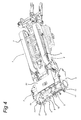
- the device according to the invention shown in figures 1- 5 comprises a complete bogie 1, provided with caterpillar tracks 2 by means of which the device can be moved over an uncompacted surface.
- a driver's cabin 3 is also provided on the bogie in the usual manner, in order to accommodate the operating personnel and is able, whilst viewing in a forward direction, to observe the steering and the removal of a ballasting material.
- the device is further provided with the customary drive mechanisms, not shown here.
- drum-shaped excavating element 5 mounted on the front end of the bogie by means of a sub-frame 4 that can be slewed upwards and downwards.
- this excavating element is rotatable in respect of the lateral walls 6 of the uptake body assembly 7.
- the drum-shaped excavating element 5 comprises a drum 8 and the tooth-shaped digging or excavating elements 9 and the pin-shaped digging or excavating elements 10 in a regularly distributed crosswise arrangement.
- these digging elements 9, 10 may be arranged according to a helical position, although it is also possible to opt for an annular arrangement thereof (not shown) or any other desired arrangement.
- the uptake body 7 comprises a fixed uptake surface 11.
- the uptake body 7 further comprises two uptake body sections 17, 18, each with an uptake surface section 19, 20 on the side, to which each of the walls 6 is attached.
- These uptake body sections 17, 18, and in particular the uptake surface sections 19, 20, are angled obliquely in and directed upwardly and towards the rear.
- the uptake body sections 17, 18 can be moved away from each other or towards each other by means of the hydraulic piston/cylinder device 23. Accordingly, the uptake surface sections 19, 20 slide across the fixed base sections 29, as shown in figures 6 and 7 .
- These base sections 29 are fixed with respect to the fixed frame 33 of the uptake body 7.
- the hydraulic piston/cylinder devices 23 are attached on the one hand to the fixed extensors 24 of the frame 33 and, on the other hand, to the supports 25 of the uptake surface sections 17, 18.
- the uptake surface sections 19, 20 each slide across a corresponding fixed base section 29, such that the ballasting material collected can be reliably fed towards the centre to the conveyor belt 12.
- the fixed base sections 29 are constructed with an oblique portion, such that a trough-like shape is created that promotes the collection and disposal of the ballasting material by means of the conveyor belt 12. This central feed is further promoted by means of the rotors 26.
- the drum 8 comprises two drum sections 13, 14, each provided with lugs 15 and slots 22 enclosed between them.
- the lugs 15 of the one drum section 13 fit into the slots 22 of the other drum section 14, and vice versa. It is thereby possible to vary the width of the drum 8 along with the uptake body 7, notably between the narrow position shown in figure 1 and the wide position shown in figure 2 .
- the device according to the invention travels in a forward direction, whilst the drum-shaped excavating element 5 rotates such that the pin-shaped digging elements 9, 10 dig into, loosen and transport the ballasting material in a backwards direction to the uptake body 7.
- the ballasting material that may initially be tightly compacted, is thus loosened by means of the digging elements 9, 10 and at the same time, or immediately thereafter, transported to the uptake body.
- the conveyor belt 12 is provided, mounted obliquely on the bogie, and connected to the uptake body 7 for carrying away the ballasting material thus obtained obliquely in an upward direction and to the rear.
- a conveyor belt 13 provided on the bogie that can be slewed to the right and to the left, onto which the ballasting material is collected which is taken up by the obliquely mounted conveyor belt 12. With the aid of the pivotal conveyor belt 13, this ballasting material can then be carried away in the desired direction, for example to a wagon on an adjacent track (not shown).
- the drum 8 comprises the drum sections 13, 14, that can be moved toward each other and away from each under the effect of the hydraulic piston/cylinder device 23.
- the drum sections 13, 14 are each provided with lugs 15 and slots 22 enclosed between them.
- the lugs 15 of the one drum section 13 fit into the slots 22 of the other drum section 14, and vice versa. It is thereby possible to vary the width of the drum 8, notably between the narrow position shown in figure 1 and the wide position shown in figure 2 .
- the ballasting material is transported under the effect of the digging elements 9, 10 onto the uptake surface sections 19, 20 and henceforth onto the conveyor belt 12.
- the motors 28, for driving the related rotors 26, are arranged within the housings 27.
- the tooth-shaped digging elements 9 have a particular orientation.
- the flat tooth surfaces 21 thereof are positioned obliquely so that such a centering effect is achieved, in conjunction with the direction of rotation of the excavating element 5, as indicated by the curved arrow.
Landscapes
- Engineering & Computer Science (AREA)
- Architecture (AREA)
- Civil Engineering (AREA)
- Structural Engineering (AREA)
- Machines For Laying And Maintaining Railways (AREA)
- Excavating Of Shafts Or Tunnels (AREA)
Applications Claiming Priority (1)
| Application Number | Priority Date | Filing Date | Title |
|---|---|---|---|
| NL2001478A NL2001478C2 (nl) | 2008-04-14 | 2008-04-14 | Inrichting en werkwijze voor het verwijderen van ballastmateriaal van een ballastbed. |
Publications (2)
| Publication Number | Publication Date |
|---|---|
| EP2110476A2 true EP2110476A2 (de) | 2009-10-21 |
| EP2110476A3 EP2110476A3 (de) | 2011-04-13 |
Family
ID=40010467
Family Applications (1)
| Application Number | Title | Priority Date | Filing Date |
|---|---|---|---|
| EP09157871A Withdrawn EP2110476A3 (de) | 2008-04-14 | 2009-04-14 | Vorrichtung und Verfahren zur Entfernung von Schottermaterial eines Schotterbetts |
Country Status (2)
| Country | Link |
|---|---|
| EP (1) | EP2110476A3 (de) |
| NL (1) | NL2001478C2 (de) |
Families Citing this family (1)
| Publication number | Priority date | Publication date | Assignee | Title |
|---|---|---|---|---|
| CN111172824B (zh) * | 2020-01-30 | 2025-03-04 | 华东交通大学 | 一种铁道道床石渣回收装置 |
Citations (2)
| Publication number | Priority date | Publication date | Assignee | Title |
|---|---|---|---|---|
| FR1387729A (fr) | 1964-04-07 | 1965-01-29 | Machine mobile pour le nettoyage du ballast de voies ferrées | |
| EP1348057A1 (de) | 2000-12-22 | 2003-10-01 | DBT GB Limited | Vorrichtung und verfahren zur entfernung von schotterbettung |
Family Cites Families (6)
| Publication number | Priority date | Publication date | Assignee | Title |
|---|---|---|---|---|
| GB964044A (en) * | 1961-02-23 | 1964-07-15 | Mannix Co Ltd | Railroad ballast removing device |
| CH394266A (de) * | 1961-12-30 | 1965-06-30 | Reichsbahn Der Generaldirektor | Maschine zur Reinigung des Schotters bei gleislosen Bettungen |
| AU450848B2 (en) * | 1969-10-27 | 1974-07-04 | George Moss Pty. Ltd | Tie bed scarifier |
| US3693512A (en) * | 1971-01-21 | 1972-09-26 | Barber Greene Co | Apparatus for handling particulate material |
| DE3911947A1 (de) * | 1989-04-12 | 1990-02-15 | Jgs Ingenieurbuero Gmbh | Fraeswalze |
| US5579553A (en) * | 1995-07-17 | 1996-12-03 | Holley Engineering Company, Inc. | Ballast broom with auger and method |
-
2008
- 2008-04-14 NL NL2001478A patent/NL2001478C2/nl not_active IP Right Cessation
-
2009
- 2009-04-14 EP EP09157871A patent/EP2110476A3/de not_active Withdrawn
Patent Citations (2)
| Publication number | Priority date | Publication date | Assignee | Title |
|---|---|---|---|---|
| FR1387729A (fr) | 1964-04-07 | 1965-01-29 | Machine mobile pour le nettoyage du ballast de voies ferrées | |
| EP1348057A1 (de) | 2000-12-22 | 2003-10-01 | DBT GB Limited | Vorrichtung und verfahren zur entfernung von schotterbettung |
Also Published As
| Publication number | Publication date |
|---|---|
| EP2110476A3 (de) | 2011-04-13 |
| NL2001478C2 (nl) | 2009-10-19 |
Similar Documents
| Publication | Publication Date | Title |
|---|---|---|
| AU2015330130B2 (en) | Cutting apparatus using a clearing arrangement | |
| RU2749518C2 (ru) | Горная машина с множеством врубовых головок | |
| JP6055972B2 (ja) | 表層土壌の剥ぎ取り収集車両及びバケット | |
| EP3070206A1 (de) | Grabenfräse mit weitem ausleger | |
| US4616880A (en) | Continuous excavating machine | |
| US11421398B2 (en) | Padding machine | |
| EP2110476A2 (de) | Vorrichtung und Verfahren zur Entfernung von Schottermaterial eines Schotterbetts | |
| US4731941A (en) | Dragline hoe, method and apparatus | |
| JP2018053586A (ja) | トンネル掘進機 | |
| JP5528049B2 (ja) | トンネル掘削装置 | |
| JP5185797B2 (ja) | 地盤の掘削装置および掘削方法 | |
| JPS61502827A (ja) | 岩石掘削機 | |
| US2709312A (en) | Side collector for mobile loader | |
| JP5116993B2 (ja) | 異形断面掘削用トンネル掘削機 | |
| CN86106946A (zh) | 改进的拉铲挖掘设备 | |
| JP2001280078A (ja) | 掘進機の掘進方法 | |
| JP4997793B2 (ja) | 掘削装置及び掘削方法 | |
| US3757439A (en) | Method of excavating trenches of considerable width | |
| EP2751345A1 (de) | Aufhängungssystem für vorderseitige arbeitswerkzeuge bei einem meliorationsgerät | |
| KR20110029577A (ko) | 이물질 침투 방지수단이 구비된 건설장비의 하부 프레임 | |
| JP2597348B2 (ja) | 掘り取り機類の土砂搬出装置 | |
| JP5797604B2 (ja) | 表土剥ぎ取り機 | |
| US20090288319A1 (en) | Earth Moving Apparatus and Method | |
| JP2001349184A (ja) | 矩形断面トンネル掘削機 | |
| JP2006052595A (ja) | 作業機械の表土剥ぎ装置及び作業機械 |
Legal Events
| Date | Code | Title | Description |
|---|---|---|---|
| PUAI | Public reference made under article 153(3) epc to a published international application that has entered the european phase |
Free format text: ORIGINAL CODE: 0009012 |
|
| AK | Designated contracting states |
Kind code of ref document: A2 Designated state(s): AT BE BG CH CY CZ DE DK EE ES FI FR GB GR HR HU IE IS IT LI LT LU LV MC MK MT NL NO PL PT RO SE SI SK TR |
|
| PUAL | Search report despatched |
Free format text: ORIGINAL CODE: 0009013 |
|
| AK | Designated contracting states |
Kind code of ref document: A3 Designated state(s): AT BE BG CH CY CZ DE DK EE ES FI FR GB GR HR HU IE IS IT LI LT LU LV MC MK MT NL NO PL PT RO SE SI SK TR |
|
| STAA | Information on the status of an ep patent application or granted ep patent |
Free format text: STATUS: THE APPLICATION IS DEEMED TO BE WITHDRAWN |
|
| 18D | Application deemed to be withdrawn |
Effective date: 20111014 |