EP2110527A2 - Véhicule utilitaire doté d'un moteur à combustion interne et système de récupération de chaleur utilisant sa source de chaleur - Google Patents
Véhicule utilitaire doté d'un moteur à combustion interne et système de récupération de chaleur utilisant sa source de chaleur Download PDFInfo
- Publication number
- EP2110527A2 EP2110527A2 EP09002006A EP09002006A EP2110527A2 EP 2110527 A2 EP2110527 A2 EP 2110527A2 EP 09002006 A EP09002006 A EP 09002006A EP 09002006 A EP09002006 A EP 09002006A EP 2110527 A2 EP2110527 A2 EP 2110527A2
- Authority
- EP
- European Patent Office
- Prior art keywords
- muffler
- evaporator
- commercial vehicle
- wall
- exhaust
- Prior art date
- Legal status (The legal status is an assumption and is not a legal conclusion. Google has not performed a legal analysis and makes no representation as to the accuracy of the status listed.)
- Granted
Links
Images





Classifications
-
- F—MECHANICAL ENGINEERING; LIGHTING; HEATING; WEAPONS; BLASTING
- F02—COMBUSTION ENGINES; HOT-GAS OR COMBUSTION-PRODUCT ENGINE PLANTS
- F02G—HOT GAS OR COMBUSTION-PRODUCT POSITIVE-DISPLACEMENT ENGINE PLANTS; USE OF WASTE HEAT OF COMBUSTION ENGINES; NOT OTHERWISE PROVIDED FOR
- F02G5/00—Profiting from waste heat of combustion engines, not otherwise provided for
- F02G5/02—Profiting from waste heat of exhaust gases
-
- F—MECHANICAL ENGINEERING; LIGHTING; HEATING; WEAPONS; BLASTING
- F01—MACHINES OR ENGINES IN GENERAL; ENGINE PLANTS IN GENERAL; STEAM ENGINES
- F01N—GAS-FLOW SILENCERS OR EXHAUST APPARATUS FOR MACHINES OR ENGINES IN GENERAL; GAS-FLOW SILENCERS OR EXHAUST APPARATUS FOR INTERNAL-COMBUSTION ENGINES
- F01N1/00—Silencing apparatus characterised by method of silencing
- F01N1/08—Silencing apparatus characterised by method of silencing by reducing exhaust energy by throttling or whirling
-
- F—MECHANICAL ENGINEERING; LIGHTING; HEATING; WEAPONS; BLASTING
- F01—MACHINES OR ENGINES IN GENERAL; ENGINE PLANTS IN GENERAL; STEAM ENGINES
- F01N—GAS-FLOW SILENCERS OR EXHAUST APPARATUS FOR MACHINES OR ENGINES IN GENERAL; GAS-FLOW SILENCERS OR EXHAUST APPARATUS FOR INTERNAL-COMBUSTION ENGINES
- F01N5/00—Exhaust or silencing apparatus combined or associated with devices profiting by exhaust energy
- F01N5/02—Exhaust or silencing apparatus combined or associated with devices profiting by exhaust energy the devices using heat
-
- F—MECHANICAL ENGINEERING; LIGHTING; HEATING; WEAPONS; BLASTING
- F01—MACHINES OR ENGINES IN GENERAL; ENGINE PLANTS IN GENERAL; STEAM ENGINES
- F01N—GAS-FLOW SILENCERS OR EXHAUST APPARATUS FOR MACHINES OR ENGINES IN GENERAL; GAS-FLOW SILENCERS OR EXHAUST APPARATUS FOR INTERNAL-COMBUSTION ENGINES
- F01N2240/00—Combination or association of two or more different exhaust treating devices, or of at least one such device with an auxiliary device, not covered by indexing codes F01N2230/00 or F01N2250/00, one of the devices being
- F01N2240/02—Combination or association of two or more different exhaust treating devices, or of at least one such device with an auxiliary device, not covered by indexing codes F01N2230/00 or F01N2250/00, one of the devices being a heat exchanger
-
- F—MECHANICAL ENGINEERING; LIGHTING; HEATING; WEAPONS; BLASTING
- F01—MACHINES OR ENGINES IN GENERAL; ENGINE PLANTS IN GENERAL; STEAM ENGINES
- F01N—GAS-FLOW SILENCERS OR EXHAUST APPARATUS FOR MACHINES OR ENGINES IN GENERAL; GAS-FLOW SILENCERS OR EXHAUST APPARATUS FOR INTERNAL-COMBUSTION ENGINES
- F01N2590/00—Exhaust or silencing apparatus adapted to particular use, e.g. for military applications, airplanes, submarines
- F01N2590/08—Exhaust or silencing apparatus adapted to particular use, e.g. for military applications, airplanes, submarines for heavy duty applications, e.g. trucks, buses, tractors, locomotives
-
- Y—GENERAL TAGGING OF NEW TECHNOLOGICAL DEVELOPMENTS; GENERAL TAGGING OF CROSS-SECTIONAL TECHNOLOGIES SPANNING OVER SEVERAL SECTIONS OF THE IPC; TECHNICAL SUBJECTS COVERED BY FORMER USPC CROSS-REFERENCE ART COLLECTIONS [XRACs] AND DIGESTS
- Y02—TECHNOLOGIES OR APPLICATIONS FOR MITIGATION OR ADAPTATION AGAINST CLIMATE CHANGE
- Y02T—CLIMATE CHANGE MITIGATION TECHNOLOGIES RELATED TO TRANSPORTATION
- Y02T10/00—Road transport of goods or passengers
- Y02T10/10—Internal combustion engine [ICE] based vehicles
- Y02T10/12—Improving ICE efficiencies
Definitions
- the invention relates according to the preamble of claim 1, a commercial vehicle, in particular trucks, with an internal combustion engine and a heat recovery system and other features, as indicated in detail.
- the object of the invention is to find space-saving accommodation for the evaporator, despite the limited space available in the commercial vehicle.
- the inventive placement of the evaporator in or on a muffler or exhaust pipe ensures that the placement of other vehicle parts is not hindered.
- optimum utilization of the residual heat of the exhaust gas for a transfer of a liquid circulation medium in its vaporous state is possible, which vapor medium in turn fed to an expander and by means of this in the engine performance-increasing deliverable mechanical energy is convertible.
- Such a heat recovery system also has the further advantage that, after other heat sources of the internal combustion engine such as the cooling water and / or recirculated exhaust are also used, the heat development of powerful combustion engines can be limited and thus the necessary cooling capacity of the radiator and thus their size can be limited ,
- FIGS. 1 . 4 . 7 . 9 and 11 is shown as an example of a commercial vehicle 1 each a tractor.
- the commercial vehicle 1 has a chassis 2 and a driver's cab 3 mounted thereon.
- an internal combustion engine 4 is arranged, which acts on the driven wheels 6 of the commercial vehicle 1 via a drive train 5 having a clutch and a manual transmission or an automatic transmission.
- the internal combustion engine 4 is associated with a heat recovery system utilizing its heat sources, which is discussed in detail only in those parts, as far as these parts have connections to the inventive solution.
- the internal combustion engine 4 preferably has a cooled exhaust gas recirculation and a single or multi-stage exhaust gas turbocharger.
- a muffler 8 is arranged in the exhaust line 7 of the engine 4, a muffler 8 is arranged.
- the internal combustion engine 4 is assigned as part of the heat recovery system, a medium cycle in which the waste heat of the engine 4 and / or hot engine power units such as exhaust gas recirculation line (s), turbochargers, etc., as well as operating fluids such as cooling water, charge air, exhaust, etc. by suitable devices in power increasing useful energy is convertible.
- the medium circuit at least one pump, an evaporator 9, an expander and a capacitor is provided.
- the invention relates to location and type of housing and design of the receiving organs for the evaporator 9. There are various possibilities. In a first version - see the embodiment according to Fig.
- the evaporator 9 is integrated into the muffler 8. He is either installed in the exhaust pipe 10 or replaced the exhaust pipe 10 partially.
- a second version - see the embodiment according to 4 to 6 - Is the evaporator 9 outside of the muffler 8, grown there laterally below and the exhaust pipe 10 continues after the evaporator 9 with its end portion 10b.
- a third version - see the embodiment according to Fig. 7 . 8th -
- the evaporator 9 is also outside the silencer 8, but here at the top of this grown. Again, the exhaust tail pipe 10 continues after the evaporator 9 with its vertically upwardly directed end portion 10b.
- a fourth version - see the embodiment according to Fig.
- evaporator 9 and 10 - Is the evaporator 9 in the outgoing from the muffler 8 and behind the cab 3 raised tailpipe 10 either installed or replaced the exhaust pipe 10 partially.
- a fifth version - see the embodiment according to Fig. 11 and 12 -
- the evaporator 9 is integrated into a muffler 8, which is installed in a raised behind the cab 3 exhaust pipe 28.
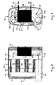
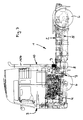
- the in the commercial vehicle 1 according to Fig. 1 installed adjacent to the engine 4 and attached to the frame of the chassis 2 muffler 8 can as in FIGS. 2 and 3 realized realized.
- This muffler 8 is barrel-shaped and has a front floor 11 and a rear floor 12, a hollow cylindrical peripheral outer wall 13 connecting the two floors 11, 12, inside an inlet space 16, separated by an intermediate wall 14 from an outlet space 15, into the inlet space 16 ausmündendes inlet pipe 17 and a tailpipe 10 on.
- the tailpipe 10 is arranged with its inlet portion 10a in the outlet space 15 and led out after the evaporator 9 with its output portion 10b in the region of the outlet space 15 limiting bottom 12 either through this or through the peripheral outer wall 13 of the muffler 8.
- the evaporator 9 is either installed in the input section 10a of the exhaust tailpipe 10 or replaces a part of the tailpipe 10 between its inlet section 10a and outlet section 10b. In the latter case, the evaporator 9 is fixed to the bottom 12 of the muffler 8.
- the muffler 8 shown also more exhaust aftertreatment modules 18 are arranged and held there by the gas-tight intermediate wall 14 and a gas-permeable support wall 19 spaced therefrom.
- Each of these exhaust aftertreatment modules 18 includes incorporated in a housing, for example, a particle separator or filter and / or at least one catalyst. How out FIGS. 2 and 3 it can be seen, in this embodiment, the evaporator 9 is fixed to the inside of the outlet space 15 limiting bottom 12 of the muffler 8.
- a connecting piece 20 is provided for the introduction of liquid circulating medium and at the top a connecting piece 21 for the discharge of the circulating medium transferred in the vaporous state of aggregation.
- Both connecting pieces 20, 21 are led out of the evaporator 9, starting through the adjacent bottom 12 or adjacent region of the peripheral outer wall 13 of the muffler 8 therethrough and there connected externally with a symbolized by an arrow 22 supply line for the liquid circulation medium or with a symbolized by an arrow 23 derivative of the vaporous circulation medium.
- Fig. 1 the position of the evaporator 9 on the commercial vehicle 1 is made visible by a black-colored field in the region of the muffler 8.
- a silencer 8 is used, which, as shown FIGS. 5 and 6 to a large extent, those of FIGS. 2 and 3 corresponds, but has the evaporator 9 elsewhere, namely outside grown laterally down. It will therefore be in FIGS. 5 and 6 for the same or corresponding parts, the same reference numerals as in FIGS. 2 and 3 used.
- FIGS. 5 and 6 for the same or corresponding parts, the same reference numerals as in FIGS. 2 and 3 used.
- FIGS. 5 and 6 for the same or corresponding parts, the same reference numerals as in FIGS. 2 and 3 used.
- Fig. 5 In this example is - how good Fig. 5 can be seen - the evaporator 9 in a housing 9 'integrated, which is fixed laterally outside at the bottom outer circumferential wall 13 of the muffler 8 in the region of the outlet space 15 limiting bottom 12. In this area, the peripheral outer wall 13 of the muffler 8 on a breakthrough.
- the tailpipe 10 is led with its internally of the outlet chamber 15 arranged input section 10a to the evaporator 9 and continues outside the muffler 8 exit of the evaporator 9 in the region of an outlet opening 9 "of the housing 9 'with its output section 10b
- the evaporator 9 has a lower connecting piece 20, which is connected to a supply line 22 for liquid circulating medium, and an upper connecting piece 21, which is connected to a discharge line 23 for the vaporous medium Fig. 4 the arrangement of this evaporator 9 in the commercial vehicle 1 is also made visible by a black-colored field on the muffler 8.
- a silencer 8 is also used which corresponds to those of Fig. 5, 6 corresponds, but has the evaporator 9 elsewhere, namely grown on the outside. It is therefore also in Fig. 7 . 8th the same or corresponding parts with the same reference number attracted.
- the evaporator 9 - as well Fig. 8 seen - grown with its housing on top of the peripheral outer wall 13 of the muffler 8. In this area, the peripheral outer wall 13 of the muffler 8 on a breakthrough.
- the tailpipe 10 is with its input portion 10a within the outlet space 15 in the region of this limiting Bottom 12 led to the evaporator 9 and continues outside the muffler 8 output of the evaporator 9 with its arranged substantially vertically behind the cab 3 output section 10 b on. This is stabilized by several holders and struts 10c positionally with respect to the muffler 8.
- the evaporator 9 is not here attached to the muffler 8, but integrated into an end portion 10 b of the rear of the cab 3 exhaust tailpipe 10, which end portion 10 b - as out Fig. 10 apparent - the output of the muffler 8 connects.
- the evaporator 9 is either installed in this exhaust tailpipe section 10b, preferably adjacent to the muffler 8 or not far from it, or partially replaces the tailpipe section 10b.
- the tailpipe 10 is here also stabilized in position with respect to the muffler 8 by special holders / struts 10c.
- the evaporator 9 has a lower connecting piece 20, to which a feed line 22 for the liquid circulating medium is connected, and an upper connecting piece 21, to which a discharge line 23 for the vaporous circulating medium is connected is.
- the location of this evaporator 9 on the commercial vehicle according to Fig. 9 is there also made visible by a black-colored field.
- the muffler 8 is formed by a behind the cab 3 substantially vertically arranged hollow cylinder 25 which is closed at the top and bottom by a respective bottom 26 and 27 respectively.
- This silencer 8 is - as well Fig. 12 can be seen - connected via its bottom 26 at the inflow-side section 28/1 and via its bottom 27 at the downstream section 28/2 of the rear of the cab 3 pulled-up exhaust pipe 28.
- this silencer 8 of the exhaust aftertreatment serving catalysts and / or filters (not shown) and the evaporator 9 are integrated.
- This evaporator 9 also has a lower connecting piece 20 and an upper connecting piece 21, which through the hollow cylindrical wall 25th of the muffler 8 passes out of this and there outside (20) to the supply line 22 for the liquid circulation medium or (21) are connected to the discharge 23 for the vapor circulation medium.
- the exhaust pipe 28 is fixed in position with the muffler 8 by holders and struts 29 with respect to the inflow-side part of the exhaust line 7 and with respect to the chassis 2.
- Fig. 11 is the location of the evaporator 9 on the local commercial vehicle 1 also indicated by a black silencer on the muffler 8 field.
- the evaporator 9 has such a construction and construction which is suitable for converting the liquid circulation medium supplied via the supply line 22 into its vaporous state of matter as it flows through it with the aid of the thermal residual heat utilization of the exhaust gas flowing past.
- the supplied liquid circulation medium may, but need not, be preheated due to a previous heat exchange in the heat recovery circuit.
- the converted by means of the evaporator 9 in its vaporous state of aggregation circulation medium is fed via the discharge line 23 in the heat recovery circuit an expander, which converts the steam energy into mechanical energy, which is drivingly effective on the crankshaft of the engine 4 as an additional drive power.
Landscapes
- Engineering & Computer Science (AREA)
- Chemical & Material Sciences (AREA)
- Combustion & Propulsion (AREA)
- Mechanical Engineering (AREA)
- General Engineering & Computer Science (AREA)
- Air-Conditioning For Vehicles (AREA)
- Exhaust Silencers (AREA)
- Exhaust Gas After Treatment (AREA)
- Supercharger (AREA)
- Cooling, Air Intake And Gas Exhaust, And Fuel Tank Arrangements In Propulsion Units (AREA)
Priority Applications (1)
| Application Number | Priority Date | Filing Date | Title |
|---|---|---|---|
| PL09002006T PL2110527T3 (pl) | 2008-04-14 | 2009-02-13 | Pojazd użytkowy z silnikiem spalinowym i wykorzystującym jego źródła ciepła systemem odzyskiwania ciepła |
Applications Claiming Priority (1)
| Application Number | Priority Date | Filing Date | Title |
|---|---|---|---|
| AT0057608A AT505547B1 (de) | 2008-04-14 | 2008-04-14 | Nutzfahrzeug mit einem verbrennungsmotor und einem dessen wärmequellen ausnutzenden wärmerückgewinnungssystem |
Publications (3)
| Publication Number | Publication Date |
|---|---|
| EP2110527A2 true EP2110527A2 (fr) | 2009-10-21 |
| EP2110527A3 EP2110527A3 (fr) | 2010-02-24 |
| EP2110527B1 EP2110527B1 (fr) | 2012-01-04 |
Family
ID=40373461
Family Applications (1)
| Application Number | Title | Priority Date | Filing Date |
|---|---|---|---|
| EP09002006A Not-in-force EP2110527B1 (fr) | 2008-04-14 | 2009-02-13 | Véhicule utilitaire doté d'un moteur à combustion interne et système de récupération de chaleur utilisant sa source de chaleur |
Country Status (7)
| Country | Link |
|---|---|
| US (1) | US8707688B2 (fr) |
| EP (1) | EP2110527B1 (fr) |
| CN (1) | CN101607524B (fr) |
| AT (2) | AT505547B1 (fr) |
| BR (1) | BRPI0901355B1 (fr) |
| PL (1) | PL2110527T3 (fr) |
| RU (1) | RU2412851C2 (fr) |
Cited By (1)
| Publication number | Priority date | Publication date | Assignee | Title |
|---|---|---|---|---|
| US10240488B2 (en) | 2014-04-30 | 2019-03-26 | MAHLE Behr GmbH & Co. KG | Exhaust gas system for a motor vehicle |
Families Citing this family (9)
| Publication number | Priority date | Publication date | Assignee | Title |
|---|---|---|---|---|
| US8230678B2 (en) * | 2007-06-21 | 2012-07-31 | Daimler Trucks North America Llc | Treatment of diesel engine exhaust |
| US8397504B2 (en) * | 2010-02-08 | 2013-03-19 | Global Alternative Fuels, Llc | Method and apparatus to recover and convert waste heat to mechanical energy |
| SE535680C2 (sv) * | 2011-03-17 | 2012-11-06 | Scania Cv Ab | Arrangemang för att omvandla värmeenergi till mekanisk energi i ett fordon |
| EP2662545B1 (fr) | 2012-05-11 | 2016-12-28 | Caterpillar Motoren GmbH & Co. KG | Dispositif d'évacuation de chauffage par rayonnement |
| DE102013012852A1 (de) | 2013-08-02 | 2015-02-05 | Daimler Ag | Vorrichtung zur Energierückgewinnung aus einem Abgasstrom einer Verbrennungskraftmaschine |
| AT517965B1 (de) * | 2016-03-22 | 2017-06-15 | MAN Truck & Bus Österreich AG | Anordnung von Nebenaggregaten bei einer Brennkraftmaschine |
| US11136905B2 (en) * | 2017-09-22 | 2021-10-05 | Tenneco Gmbh | Rankine power system with working fluid tank and control system |
| CN113339326B (zh) * | 2021-06-08 | 2023-11-14 | 江苏悦达专用车有限公司 | 一种水泵加热系统 |
| CN118596825A (zh) * | 2024-06-20 | 2024-09-06 | 东风商用车有限公司 | 一种车辆排气系统及汽车 |
Citations (3)
| Publication number | Priority date | Publication date | Assignee | Title |
|---|---|---|---|---|
| DE4141061A1 (de) | 1991-12-13 | 1993-06-17 | Schaeffler Waelzlager Kg | Verfahren und vorrichtung zur herstellung eines mit waelzkoerpern gefuellten waelzlagerkaefigs |
| WO2000031400A2 (fr) | 1998-11-24 | 2000-06-02 | Claudio Filippone | Moteur miniature d'energie residuelle |
| EP1249585A1 (fr) | 2000-01-21 | 2002-10-16 | Honda Giken Kogyo Kabushiki Kaisha | Echangeurs de chaleur d'un moteur a combustion interne a plusieurs cylindres |
Family Cites Families (16)
| Publication number | Priority date | Publication date | Assignee | Title |
|---|---|---|---|---|
| US3280903A (en) * | 1964-12-21 | 1966-10-25 | Universal Silencer Corp | Exhaust silencer and heat recovery unit |
| US3501095A (en) * | 1968-03-13 | 1970-03-17 | Randall A Peterson | Hot air heating apparatus for tractor |
| IT1003514B (it) * | 1971-04-05 | 1976-06-10 | Shuffman O | Apparato per la purifi cazione di gas di combustione |
| US3748830A (en) * | 1972-05-19 | 1973-07-31 | Ross S | Method and apparatus for purifying combustion gases |
| JPS6131131Y2 (fr) * | 1981-03-26 | 1986-09-10 | ||
| SU1671921A1 (ru) * | 1989-05-23 | 1991-08-23 | Белорусский технологический институт им.С.М.Кирова | Двигатель внутреннего сгорани |
| DE4141051A1 (de) * | 1991-12-13 | 1993-06-17 | Wojciech Slomkowski | Brennkraftmaschine mit einer dampfturbinenanlage als leistungsgekoppelter zusatzeinrichtung |
| DE60113646T2 (de) * | 2000-01-21 | 2006-03-16 | Honda Giken Kogyo K.K. | Abgasreinigungsvorrichtung und brennkraftmaschine |
| CN2481853Y (zh) * | 2001-06-18 | 2002-03-13 | 戴中华 | 发动机热能、废气能量回收再利用装置 |
| US6951697B2 (en) * | 2001-09-11 | 2005-10-04 | Donaldson Company, Inc. | Integrated systems for use with fuel cells, and methods |
| US6871489B2 (en) * | 2003-04-16 | 2005-03-29 | Arvin Technologies, Inc. | Thermal management of exhaust systems |
| DE10340105A1 (de) * | 2003-08-30 | 2005-03-24 | Man Nutzfahrzeuge Ag | Abgasstrang einer Brennkraftmaschine mit eingebautem Vor- und Hauptschalldämpfer |
| BRPI0511051A (pt) * | 2004-05-11 | 2007-11-27 | Modine Mfg Co | unidade integrada de trocador de calor e silencioso |
| US7063134B2 (en) * | 2004-06-24 | 2006-06-20 | Tenneco Automotive Operating Company Inc. | Combined muffler/heat exchanger |
| GB0618867D0 (en) * | 2006-09-25 | 2006-11-01 | Univ Sussex The | Vehicle power supply system |
| CN101059108A (zh) * | 2007-06-06 | 2007-10-24 | 上海毅知实业有限公司 | 车用内燃机余热回收利用机构及方法 |
-
2008
- 2008-04-14 AT AT0057608A patent/AT505547B1/de not_active IP Right Cessation
-
2009
- 2009-02-13 EP EP09002006A patent/EP2110527B1/fr not_active Not-in-force
- 2009-02-13 AT AT09002006T patent/ATE540207T1/de active
- 2009-02-13 PL PL09002006T patent/PL2110527T3/pl unknown
- 2009-04-13 RU RU2009113833/11A patent/RU2412851C2/ru active
- 2009-04-14 BR BRPI0901355A patent/BRPI0901355B1/pt not_active IP Right Cessation
- 2009-04-14 US US12/423,149 patent/US8707688B2/en not_active Expired - Fee Related
- 2009-04-14 CN CN200910132727.4A patent/CN101607524B/zh not_active Expired - Fee Related
Patent Citations (3)
| Publication number | Priority date | Publication date | Assignee | Title |
|---|---|---|---|---|
| DE4141061A1 (de) | 1991-12-13 | 1993-06-17 | Schaeffler Waelzlager Kg | Verfahren und vorrichtung zur herstellung eines mit waelzkoerpern gefuellten waelzlagerkaefigs |
| WO2000031400A2 (fr) | 1998-11-24 | 2000-06-02 | Claudio Filippone | Moteur miniature d'energie residuelle |
| EP1249585A1 (fr) | 2000-01-21 | 2002-10-16 | Honda Giken Kogyo Kabushiki Kaisha | Echangeurs de chaleur d'un moteur a combustion interne a plusieurs cylindres |
Cited By (1)
| Publication number | Priority date | Publication date | Assignee | Title |
|---|---|---|---|---|
| US10240488B2 (en) | 2014-04-30 | 2019-03-26 | MAHLE Behr GmbH & Co. KG | Exhaust gas system for a motor vehicle |
Also Published As
| Publication number | Publication date |
|---|---|
| ATE540207T1 (de) | 2012-01-15 |
| RU2412851C2 (ru) | 2011-02-27 |
| EP2110527B1 (fr) | 2012-01-04 |
| BRPI0901355B1 (pt) | 2020-05-05 |
| US20090255243A1 (en) | 2009-10-15 |
| PL2110527T3 (pl) | 2012-06-29 |
| CN101607524B (zh) | 2014-03-05 |
| US8707688B2 (en) | 2014-04-29 |
| BRPI0901355A2 (pt) | 2009-12-01 |
| AT505547B1 (de) | 2009-02-15 |
| CN101607524A (zh) | 2009-12-23 |
| RU2009113833A (ru) | 2010-10-20 |
| EP2110527A3 (fr) | 2010-02-24 |
| AT505547A4 (de) | 2009-02-15 |
Similar Documents
| Publication | Publication Date | Title |
|---|---|---|
| EP2110527B1 (fr) | Véhicule utilitaire doté d'un moteur à combustion interne et système de récupération de chaleur utilisant sa source de chaleur | |
| EP2156041B1 (fr) | Chaîne cinématique, notamment pour des camions et des véhicules sur rails | |
| DE102017213004A1 (de) | Brennkraftmaschine | |
| DE102011105041B4 (de) | Schmiervorrichtung für einen Turbolader eines Motors für ein Fahrzeug | |
| DE102011104450A1 (de) | Turboladevorrichtung für einen Fahrzeugmotor | |
| EP2625415A1 (fr) | Filtre de recirculation de gaz d'échappement, moteur à combustion interne | |
| DE102014117007A1 (de) | Kühlmodul einer Fahrzeugklimaanlage sowie Baugruppe zur Kühlung eines Kraftfahrzeugmotors mit einem solchen Kühlmodul | |
| DE102007025173A1 (de) | Anordnung von Aufladebaueinheiten zum Aufladen einer Verbrennungskraftmaschine | |
| WO2008101978A1 (fr) | Module de gaz frais conçu pour une installation de gaz frais | |
| EP1203142A1 (fr) | Moteur a combustion interne pourvu d'un systeme d'insufflation d'air secondaire | |
| EP2157309B1 (fr) | Moteur à combustion interne | |
| DE102023000093A1 (de) | Drucklufterzeugungseinheit zum Erzeugen von Druckluft für ein pneumatisches System eines Fahrzeugs sowie batterieelektrisch betriebenes Fahrzeug mit zumindest einem pneumatischen System mit zumindest einer solchen Drucklufterzeugungseinheit | |
| EP3225811B1 (fr) | Système de modules auxiliaires pour un moteur à combustion interne | |
| EP3225810B1 (fr) | Entraînement auxiliaire pour un moteur à combustion interne | |
| DE102010063265A1 (de) | Ladeluftkühler | |
| DE19849619B4 (de) | Kühlsystem für einen Verbrennungsmotor eines Kraftfahrzeuges | |
| DE102016013926A1 (de) | Kühlvorrichtung zum Kühlen von Ladeluft für eine Verbrennungskraftmaschine | |
| DE102014005251A1 (de) | Vorrichtung zum Betreiben eines Verbrennungsmotors | |
| DE102013211701A1 (de) | Fahrzeugheizsystem sowie Verfahren zum Heizen des Innenraums eines Fahrzeugs mit einem Fahrzeugheizsystem | |
| DE102019004384A1 (de) | Vorrichtung und Verfahren zur Reinigung von Abgasen | |
| DE102009057802B4 (de) | Kühlkreislauf für eine Brennkraftmaschine | |
| DE102014201937A1 (de) | Ladeluftkühler | |
| DE102016012355A1 (de) | Verbrennungskraftmaschine für ein Kraftfahrzeug, insbesondere für einen Kraftwagen | |
| DE102016213590A1 (de) | Brennkraftmaschine mit Ladeluftkühlung durch Klimaanlagensystem | |
| DE202013102685U1 (de) | Fahrzeugheizsystem zum Heizen des Innenraums eines Fahrzeugs |
Legal Events
| Date | Code | Title | Description |
|---|---|---|---|
| PUAI | Public reference made under article 153(3) epc to a published international application that has entered the european phase |
Free format text: ORIGINAL CODE: 0009012 |
|
| AK | Designated contracting states |
Kind code of ref document: A2 Designated state(s): AT BE BG CH CY CZ DE DK EE ES FI FR GB GR HR HU IE IS IT LI LT LU LV MC MK MT NL NO PL PT RO SE SI SK TR |
|
| AX | Request for extension of the european patent |
Extension state: AL BA RS |
|
| PUAL | Search report despatched |
Free format text: ORIGINAL CODE: 0009013 |
|
| AK | Designated contracting states |
Kind code of ref document: A3 Designated state(s): AT BE BG CH CY CZ DE DK EE ES FI FR GB GR HR HU IE IS IT LI LT LU LV MC MK MT NL NO PL PT RO SE SI SK TR |
|
| AX | Request for extension of the european patent |
Extension state: AL BA RS |
|
| 17P | Request for examination filed |
Effective date: 20100315 |
|
| 17Q | First examination report despatched |
Effective date: 20100422 |
|
| AKX | Designation fees paid |
Designated state(s): AT BE BG CH CY CZ DE DK EE ES FI FR GB GR HR HU IE IS IT LI LT LU LV MC MK MT NL NO PL PT RO SE SI SK TR |
|
| RIC1 | Information provided on ipc code assigned before grant |
Ipc: F01N 1/08 20060101ALI20110715BHEP Ipc: F01N 5/02 20060101AFI20110715BHEP Ipc: F02G 5/02 20060101ALI20110715BHEP |
|
| GRAP | Despatch of communication of intention to grant a patent |
Free format text: ORIGINAL CODE: EPIDOSNIGR1 |
|
| GRAS | Grant fee paid |
Free format text: ORIGINAL CODE: EPIDOSNIGR3 |
|
| GRAA | (expected) grant |
Free format text: ORIGINAL CODE: 0009210 |
|
| AK | Designated contracting states |
Kind code of ref document: B1 Designated state(s): AT BE BG CH CY CZ DE DK EE ES FI FR GB GR HR HU IE IS IT LI LT LU LV MC MK MT NL NO PL PT RO SE SI SK TR |
|
| REG | Reference to a national code |
Ref country code: GB Ref legal event code: FG4D Free format text: NOT ENGLISH |
|
| REG | Reference to a national code |
Ref country code: CH Ref legal event code: EP |
|
| REG | Reference to a national code |
Ref country code: AT Ref legal event code: REF Ref document number: 540207 Country of ref document: AT Kind code of ref document: T Effective date: 20120115 |
|
| REG | Reference to a national code |
Ref country code: IE Ref legal event code: FG4D |
|
| RAP2 | Party data changed (patent owner data changed or rights of a patent transferred) |
Owner name: MAN TRUCK & BUS OESTERREICH AG |
|
| REG | Reference to a national code |
Ref country code: NL Ref legal event code: TD Effective date: 20120223 |
|
| REG | Reference to a national code |
Ref country code: DE Ref legal event code: R096 Ref document number: 502009002345 Country of ref document: DE Effective date: 20120308 |
|
| REG | Reference to a national code |
Ref country code: NL Ref legal event code: T3 |
|
| REG | Reference to a national code |
Ref country code: DE Ref legal event code: R081 Ref document number: 502009002345 Country of ref document: DE Owner name: MAN TRUCK & BUS OESTERREICH AG, AT Free format text: FORMER OWNER: MAN NUTZFAHRZEUGE OESTERREICH AG, STEYR, AT Effective date: 20120125 |
|
| REG | Reference to a national code |
Ref country code: SE Ref legal event code: TRGR |
|
| PG25 | Lapsed in a contracting state [announced via postgrant information from national office to epo] |
Ref country code: SI Free format text: LAPSE BECAUSE OF FAILURE TO SUBMIT A TRANSLATION OF THE DESCRIPTION OR TO PAY THE FEE WITHIN THE PRESCRIBED TIME-LIMIT Effective date: 20120104 |
|
| LTIE | Lt: invalidation of european patent or patent extension |
Effective date: 20120104 |
|
| REG | Reference to a national code |
Ref country code: PL Ref legal event code: T3 |
|
| PG25 | Lapsed in a contracting state [announced via postgrant information from national office to epo] |
Ref country code: BG Free format text: LAPSE BECAUSE OF FAILURE TO SUBMIT A TRANSLATION OF THE DESCRIPTION OR TO PAY THE FEE WITHIN THE PRESCRIBED TIME-LIMIT Effective date: 20120404 Ref country code: IS Free format text: LAPSE BECAUSE OF FAILURE TO SUBMIT A TRANSLATION OF THE DESCRIPTION OR TO PAY THE FEE WITHIN THE PRESCRIBED TIME-LIMIT Effective date: 20120504 Ref country code: HR Free format text: LAPSE BECAUSE OF FAILURE TO SUBMIT A TRANSLATION OF THE DESCRIPTION OR TO PAY THE FEE WITHIN THE PRESCRIBED TIME-LIMIT Effective date: 20120104 Ref country code: LT Free format text: LAPSE BECAUSE OF FAILURE TO SUBMIT A TRANSLATION OF THE DESCRIPTION OR TO PAY THE FEE WITHIN THE PRESCRIBED TIME-LIMIT Effective date: 20120104 Ref country code: NO Free format text: LAPSE BECAUSE OF FAILURE TO SUBMIT A TRANSLATION OF THE DESCRIPTION OR TO PAY THE FEE WITHIN THE PRESCRIBED TIME-LIMIT Effective date: 20120404 |
|
| REG | Reference to a national code |
Ref country code: IE Ref legal event code: FD4D |
|
| BERE | Be: lapsed |
Owner name: MAN NUTZFAHRZEUGE OSTERREICH AG Effective date: 20120228 |
|
| PG25 | Lapsed in a contracting state [announced via postgrant information from national office to epo] |
Ref country code: LV Free format text: LAPSE BECAUSE OF FAILURE TO SUBMIT A TRANSLATION OF THE DESCRIPTION OR TO PAY THE FEE WITHIN THE PRESCRIBED TIME-LIMIT Effective date: 20120104 Ref country code: PT Free format text: LAPSE BECAUSE OF FAILURE TO SUBMIT A TRANSLATION OF THE DESCRIPTION OR TO PAY THE FEE WITHIN THE PRESCRIBED TIME-LIMIT Effective date: 20120504 Ref country code: GR Free format text: LAPSE BECAUSE OF FAILURE TO SUBMIT A TRANSLATION OF THE DESCRIPTION OR TO PAY THE FEE WITHIN THE PRESCRIBED TIME-LIMIT Effective date: 20120405 Ref country code: FI Free format text: LAPSE BECAUSE OF FAILURE TO SUBMIT A TRANSLATION OF THE DESCRIPTION OR TO PAY THE FEE WITHIN THE PRESCRIBED TIME-LIMIT Effective date: 20120104 |
|
| PG25 | Lapsed in a contracting state [announced via postgrant information from national office to epo] |
Ref country code: MC Free format text: LAPSE BECAUSE OF NON-PAYMENT OF DUE FEES Effective date: 20120229 Ref country code: CY Free format text: LAPSE BECAUSE OF FAILURE TO SUBMIT A TRANSLATION OF THE DESCRIPTION OR TO PAY THE FEE WITHIN THE PRESCRIBED TIME-LIMIT Effective date: 20120104 |
|
| PG25 | Lapsed in a contracting state [announced via postgrant information from national office to epo] |
Ref country code: RO Free format text: LAPSE BECAUSE OF FAILURE TO SUBMIT A TRANSLATION OF THE DESCRIPTION OR TO PAY THE FEE WITHIN THE PRESCRIBED TIME-LIMIT Effective date: 20120104 Ref country code: IE Free format text: LAPSE BECAUSE OF FAILURE TO SUBMIT A TRANSLATION OF THE DESCRIPTION OR TO PAY THE FEE WITHIN THE PRESCRIBED TIME-LIMIT Effective date: 20120104 Ref country code: DK Free format text: LAPSE BECAUSE OF FAILURE TO SUBMIT A TRANSLATION OF THE DESCRIPTION OR TO PAY THE FEE WITHIN THE PRESCRIBED TIME-LIMIT Effective date: 20120104 Ref country code: EE Free format text: LAPSE BECAUSE OF FAILURE TO SUBMIT A TRANSLATION OF THE DESCRIPTION OR TO PAY THE FEE WITHIN THE PRESCRIBED TIME-LIMIT Effective date: 20120104 Ref country code: CZ Free format text: LAPSE BECAUSE OF FAILURE TO SUBMIT A TRANSLATION OF THE DESCRIPTION OR TO PAY THE FEE WITHIN THE PRESCRIBED TIME-LIMIT Effective date: 20120104 |
|
| PLBE | No opposition filed within time limit |
Free format text: ORIGINAL CODE: 0009261 |
|
| STAA | Information on the status of an ep patent application or granted ep patent |
Free format text: STATUS: NO OPPOSITION FILED WITHIN TIME LIMIT |
|
| PG25 | Lapsed in a contracting state [announced via postgrant information from national office to epo] |
Ref country code: SK Free format text: LAPSE BECAUSE OF FAILURE TO SUBMIT A TRANSLATION OF THE DESCRIPTION OR TO PAY THE FEE WITHIN THE PRESCRIBED TIME-LIMIT Effective date: 20120104 |
|
| 26N | No opposition filed |
Effective date: 20121005 |
|
| PG25 | Lapsed in a contracting state [announced via postgrant information from national office to epo] |
Ref country code: BE Free format text: LAPSE BECAUSE OF NON-PAYMENT OF DUE FEES Effective date: 20120228 |
|
| REG | Reference to a national code |
Ref country code: DE Ref legal event code: R097 Ref document number: 502009002345 Country of ref document: DE Effective date: 20121005 |
|
| PG25 | Lapsed in a contracting state [announced via postgrant information from national office to epo] |
Ref country code: MK Free format text: LAPSE BECAUSE OF FAILURE TO SUBMIT A TRANSLATION OF THE DESCRIPTION OR TO PAY THE FEE WITHIN THE PRESCRIBED TIME-LIMIT Effective date: 20120104 |
|
| PG25 | Lapsed in a contracting state [announced via postgrant information from national office to epo] |
Ref country code: ES Free format text: LAPSE BECAUSE OF FAILURE TO SUBMIT A TRANSLATION OF THE DESCRIPTION OR TO PAY THE FEE WITHIN THE PRESCRIBED TIME-LIMIT Effective date: 20120415 |
|
| PG25 | Lapsed in a contracting state [announced via postgrant information from national office to epo] |
Ref country code: MT Free format text: LAPSE BECAUSE OF FAILURE TO SUBMIT A TRANSLATION OF THE DESCRIPTION OR TO PAY THE FEE WITHIN THE PRESCRIBED TIME-LIMIT Effective date: 20120104 |
|
| REG | Reference to a national code |
Ref country code: CH Ref legal event code: PL |
|
| GBPC | Gb: european patent ceased through non-payment of renewal fee |
Effective date: 20130213 |
|
| PG25 | Lapsed in a contracting state [announced via postgrant information from national office to epo] |
Ref country code: LI Free format text: LAPSE BECAUSE OF NON-PAYMENT OF DUE FEES Effective date: 20130228 Ref country code: CH Free format text: LAPSE BECAUSE OF NON-PAYMENT OF DUE FEES Effective date: 20130228 |
|
| PG25 | Lapsed in a contracting state [announced via postgrant information from national office to epo] |
Ref country code: GB Free format text: LAPSE BECAUSE OF NON-PAYMENT OF DUE FEES Effective date: 20130213 |
|
| PG25 | Lapsed in a contracting state [announced via postgrant information from national office to epo] |
Ref country code: LU Free format text: LAPSE BECAUSE OF NON-PAYMENT OF DUE FEES Effective date: 20120213 |
|
| PG25 | Lapsed in a contracting state [announced via postgrant information from national office to epo] |
Ref country code: HU Free format text: LAPSE BECAUSE OF FAILURE TO SUBMIT A TRANSLATION OF THE DESCRIPTION OR TO PAY THE FEE WITHIN THE PRESCRIBED TIME-LIMIT Effective date: 20090213 |
|
| REG | Reference to a national code |
Ref country code: AT Ref legal event code: MM01 Ref document number: 540207 Country of ref document: AT Kind code of ref document: T Effective date: 20140213 |
|
| PG25 | Lapsed in a contracting state [announced via postgrant information from national office to epo] |
Ref country code: AT Free format text: LAPSE BECAUSE OF NON-PAYMENT OF DUE FEES Effective date: 20140213 |
|
| REG | Reference to a national code |
Ref country code: FR Ref legal event code: PLFP Year of fee payment: 8 |
|
| REG | Reference to a national code |
Ref country code: FR Ref legal event code: PLFP Year of fee payment: 9 |
|
| REG | Reference to a national code |
Ref country code: FR Ref legal event code: PLFP Year of fee payment: 10 |
|
| REG | Reference to a national code |
Ref country code: DE Ref legal event code: R081 Ref document number: 502009002345 Country of ref document: DE Owner name: MAN TRUCK & BUS SE, DE Free format text: FORMER OWNER: MAN TRUCK & BUS OESTERREICH AG, STEYR, AT |
|
| PGFP | Annual fee paid to national office [announced via postgrant information from national office to epo] |
Ref country code: NL Payment date: 20230222 Year of fee payment: 15 |
|
| PGFP | Annual fee paid to national office [announced via postgrant information from national office to epo] |
Ref country code: FR Payment date: 20230223 Year of fee payment: 15 |
|
| PGFP | Annual fee paid to national office [announced via postgrant information from national office to epo] |
Ref country code: TR Payment date: 20230201 Year of fee payment: 15 Ref country code: SE Payment date: 20230222 Year of fee payment: 15 Ref country code: PL Payment date: 20230203 Year of fee payment: 15 Ref country code: IT Payment date: 20230220 Year of fee payment: 15 Ref country code: DE Payment date: 20230227 Year of fee payment: 15 |
|
| REG | Reference to a national code |
Ref country code: NL Ref legal event code: PD Owner name: MAN TRUCK & BUS OESTERREICH GESMBH; AT Free format text: DETAILS ASSIGNMENT: CHANGE OF OWNER(S), ASSIGNMENT; FORMER OWNER NAME: MAN TRUCK & BUS OESTERREICH GESMBH Effective date: 20231031 |
|
| REG | Reference to a national code |
Ref country code: DE Ref legal event code: R119 Ref document number: 502009002345 Country of ref document: DE |
|
| REG | Reference to a national code |
Ref country code: SE Ref legal event code: EUG |
|
| REG | Reference to a national code |
Ref country code: NL Ref legal event code: MM Effective date: 20240301 |
|
| PG25 | Lapsed in a contracting state [announced via postgrant information from national office to epo] |
Ref country code: NL Free format text: LAPSE BECAUSE OF NON-PAYMENT OF DUE FEES Effective date: 20240301 |
|
| PG25 | Lapsed in a contracting state [announced via postgrant information from national office to epo] |
Ref country code: NL Free format text: LAPSE BECAUSE OF NON-PAYMENT OF DUE FEES Effective date: 20240301 |
|
| PG25 | Lapsed in a contracting state [announced via postgrant information from national office to epo] |
Ref country code: DE Free format text: LAPSE BECAUSE OF NON-PAYMENT OF DUE FEES Effective date: 20240903 |
|
| PG25 | Lapsed in a contracting state [announced via postgrant information from national office to epo] |
Ref country code: FR Free format text: LAPSE BECAUSE OF NON-PAYMENT OF DUE FEES Effective date: 20240229 |
|
| PG25 | Lapsed in a contracting state [announced via postgrant information from national office to epo] |
Ref country code: FR Free format text: LAPSE BECAUSE OF NON-PAYMENT OF DUE FEES Effective date: 20240229 Ref country code: DE Free format text: LAPSE BECAUSE OF NON-PAYMENT OF DUE FEES Effective date: 20240903 |
|
| PG25 | Lapsed in a contracting state [announced via postgrant information from national office to epo] |
Ref country code: IT Free format text: LAPSE BECAUSE OF NON-PAYMENT OF DUE FEES Effective date: 20240213 |
|
| PG25 | Lapsed in a contracting state [announced via postgrant information from national office to epo] |
Ref country code: PL Free format text: LAPSE BECAUSE OF NON-PAYMENT OF DUE FEES Effective date: 20240213 |
|
| PG25 | Lapsed in a contracting state [announced via postgrant information from national office to epo] |
Ref country code: SE Free format text: LAPSE BECAUSE OF NON-PAYMENT OF DUE FEES Effective date: 20240214 |
|
| PG25 | Lapsed in a contracting state [announced via postgrant information from national office to epo] |
Ref country code: TR Free format text: LAPSE BECAUSE OF NON-PAYMENT OF DUE FEES Effective date: 20240213 |