EP2110559B1 - Turbomachine avec réinjection de fluide pour influencer la couche limite - Google Patents
Turbomachine avec réinjection de fluide pour influencer la couche limite Download PDFInfo
- Publication number
- EP2110559B1 EP2110559B1 EP09003693.0A EP09003693A EP2110559B1 EP 2110559 B1 EP2110559 B1 EP 2110559B1 EP 09003693 A EP09003693 A EP 09003693A EP 2110559 B1 EP2110559 B1 EP 2110559B1
- Authority
- EP
- European Patent Office
- Prior art keywords
- fluid
- point
- blade
- profile
- meridional
- Prior art date
- Legal status (The legal status is an assumption and is not a legal conclusion. Google has not performed a legal analysis and makes no representation as to the accuracy of the status listed.)
- Ceased
Links
- 239000012530 fluid Substances 0.000 title claims description 145
- 238000002347 injection Methods 0.000 title 1
- 239000007924 injection Substances 0.000 title 1
- 238000011144 upstream manufacturing Methods 0.000 claims description 14
- 230000008602 contraction Effects 0.000 claims description 2
- 238000004064 recycling Methods 0.000 description 18
- 230000002093 peripheral effect Effects 0.000 description 6
- 238000000605 extraction Methods 0.000 description 4
- 238000009825 accumulation Methods 0.000 description 3
- 150000001875 compounds Chemical class 0.000 description 2
- 230000002349 favourable effect Effects 0.000 description 2
- 238000000926 separation method Methods 0.000 description 2
- 238000010276 construction Methods 0.000 description 1
- 238000001816 cooling Methods 0.000 description 1
- 230000005484 gravity Effects 0.000 description 1
- 239000007788 liquid Substances 0.000 description 1
- 238000005457 optimization Methods 0.000 description 1
Images


Classifications
-
- F—MECHANICAL ENGINEERING; LIGHTING; HEATING; WEAPONS; BLASTING
- F04—POSITIVE - DISPLACEMENT MACHINES FOR LIQUIDS; PUMPS FOR LIQUIDS OR ELASTIC FLUIDS
- F04D—NON-POSITIVE-DISPLACEMENT PUMPS
- F04D29/00—Details, component parts, or accessories
- F04D29/66—Combating cavitation, whirls, noise, vibration or the like; Balancing
- F04D29/68—Combating cavitation, whirls, noise, vibration or the like; Balancing by influencing boundary layers
- F04D29/681—Combating cavitation, whirls, noise, vibration or the like; Balancing by influencing boundary layers especially adapted for elastic fluid pumps
-
- F—MECHANICAL ENGINEERING; LIGHTING; HEATING; WEAPONS; BLASTING
- F04—POSITIVE - DISPLACEMENT MACHINES FOR LIQUIDS; PUMPS FOR LIQUIDS OR ELASTIC FLUIDS
- F04D—NON-POSITIVE-DISPLACEMENT PUMPS
- F04D29/00—Details, component parts, or accessories
- F04D29/26—Rotors specially for elastic fluids
- F04D29/32—Rotors specially for elastic fluids for axial flow pumps
- F04D29/321—Rotors specially for elastic fluids for axial flow pumps for axial flow compressors
-
- F—MECHANICAL ENGINEERING; LIGHTING; HEATING; WEAPONS; BLASTING
- F04—POSITIVE - DISPLACEMENT MACHINES FOR LIQUIDS; PUMPS FOR LIQUIDS OR ELASTIC FLUIDS
- F04D—NON-POSITIVE-DISPLACEMENT PUMPS
- F04D29/00—Details, component parts, or accessories
- F04D29/40—Casings; Connections of working fluid
- F04D29/52—Casings; Connections of working fluid for axial pumps
- F04D29/54—Fluid-guiding means, e.g. diffusers
- F04D29/541—Specially adapted for elastic fluid pumps
- F04D29/542—Bladed diffusers
-
- F—MECHANICAL ENGINEERING; LIGHTING; HEATING; WEAPONS; BLASTING
- F04—POSITIVE - DISPLACEMENT MACHINES FOR LIQUIDS; PUMPS FOR LIQUIDS OR ELASTIC FLUIDS
- F04D—NON-POSITIVE-DISPLACEMENT PUMPS
- F04D29/00—Details, component parts, or accessories
- F04D29/40—Casings; Connections of working fluid
- F04D29/52—Casings; Connections of working fluid for axial pumps
- F04D29/54—Fluid-guiding means, e.g. diffusers
- F04D29/56—Fluid-guiding means, e.g. diffusers adjustable
- F04D29/563—Fluid-guiding means, e.g. diffusers adjustable specially adapted for elastic fluid pumps
-
- F—MECHANICAL ENGINEERING; LIGHTING; HEATING; WEAPONS; BLASTING
- F04—POSITIVE - DISPLACEMENT MACHINES FOR LIQUIDS; PUMPS FOR LIQUIDS OR ELASTIC FLUIDS
- F04D—NON-POSITIVE-DISPLACEMENT PUMPS
- F04D29/00—Details, component parts, or accessories
- F04D29/66—Combating cavitation, whirls, noise, vibration or the like; Balancing
- F04D29/68—Combating cavitation, whirls, noise, vibration or the like; Balancing by influencing boundary layers
- F04D29/681—Combating cavitation, whirls, noise, vibration or the like; Balancing by influencing boundary layers especially adapted for elastic fluid pumps
- F04D29/682—Combating cavitation, whirls, noise, vibration or the like; Balancing by influencing boundary layers especially adapted for elastic fluid pumps by fluid extraction
-
- F—MECHANICAL ENGINEERING; LIGHTING; HEATING; WEAPONS; BLASTING
- F04—POSITIVE - DISPLACEMENT MACHINES FOR LIQUIDS; PUMPS FOR LIQUIDS OR ELASTIC FLUIDS
- F04D—NON-POSITIVE-DISPLACEMENT PUMPS
- F04D29/00—Details, component parts, or accessories
- F04D29/66—Combating cavitation, whirls, noise, vibration or the like; Balancing
- F04D29/68—Combating cavitation, whirls, noise, vibration or the like; Balancing by influencing boundary layers
- F04D29/681—Combating cavitation, whirls, noise, vibration or the like; Balancing by influencing boundary layers especially adapted for elastic fluid pumps
- F04D29/684—Combating cavitation, whirls, noise, vibration or the like; Balancing by influencing boundary layers especially adapted for elastic fluid pumps by fluid injection
-
- F—MECHANICAL ENGINEERING; LIGHTING; HEATING; WEAPONS; BLASTING
- F01—MACHINES OR ENGINES IN GENERAL; ENGINE PLANTS IN GENERAL; STEAM ENGINES
- F01D—NON-POSITIVE DISPLACEMENT MACHINES OR ENGINES, e.g. STEAM TURBINES
- F01D17/00—Regulating or controlling by varying flow
- F01D17/10—Final actuators
- F01D17/12—Final actuators arranged in stator parts
- F01D17/14—Final actuators arranged in stator parts varying effective cross-sectional area of nozzles or guide conduits
- F01D17/16—Final actuators arranged in stator parts varying effective cross-sectional area of nozzles or guide conduits by means of nozzle vanes
- F01D17/162—Final actuators arranged in stator parts varying effective cross-sectional area of nozzles or guide conduits by means of nozzle vanes for axial flow, i.e. the vanes turning around axes which are essentially perpendicular to the rotor centre line
Definitions
- the invention relates to a fluid flow machine according to the features of the preamble of claim 1.
- the invention relates to a fluid flow machine having a flow path delimited by at least one wall on which at least one row of blades (rotor blades or stator blades) are arranged, with no relative movement between the wall and the blades.
- the aerodynamic load capacity and the efficiency of fluid flow machines is limited in particular by the growth and separation of boundary layers close to the housing wall.
- boundary layer control by fluid recycling is thus included in the prior art,
- the known solutions are only partially effective and very limited in their practicality. This is in part due to the fact that the boundary layer flow phenomena occurring in the sidewall region of fluid flow machines are very complex.
- the present invention thus relates to blades of fluid flow machines such as fans, compressors, pumps and fans of axial, semi-axial and radial design with gaseous or liquid working medium.
- the turbomachine may include one or more stages, each having a rotor and a stator, in some cases the stage is merely formed by a rotor.
- the rotor consists of a number of blades, which are connected to the rotating shaft of the machine and deliver energy to the working fluid.
- the rotor can be designed with or without shroud on the outer blade end.
- the stator consists of a number of stationary blades, which can be designed on the hub side as the housing side with a fixed or free blade end.
- the rotor drum and the blading are usually surrounded by a housing, in other cases, for. As in propellers or propellers, no housing exists.
- the machine may also have a stator in front of the first rotor, a so-called leading wheel. At least one stator or leader wheel may be rotatably supported, other than the stationary fixture, to vary the angle of attack. An adjustment is made for example by a spindle accessible from outside the annular channel.
- the flow machine can have at least one row of adjustable rotors.
- the turbomachine according to the invention may have two counter-rotating shafts in multiple stages, so that the rotor blade rows change the direction of rotation from stage to stage. There are no stators between successive rotors.
- the fluid flow machine can alternatively have a bypass configuration such that the single-flow annular channel divides behind a certain row of blades into two concentric annular channels, which in turn accommodate at least one additional row of blades.
- the invention relates to a fluid flow machine, with which work is applied to the flow medium. If the fluid to be recirculated removed at a point of the fluid flow machine, which has a significantly higher energy level, it comes to a loss of efficiency due to a multiple supply of work on the same fluid.
- the transfer paths in the usual recirculation of fluid between different rows of blades are usually long and thus cause correspondingly high pressure losses.
- the US 4 146 352 A describes a turbomachine with blade rows.
- a fluid removal opening is provided, which is connected via a fluid return path to a fluid supply opening.
- the fluid is removed at the pressure side of the blade and fed back to the flow path on the suction side.
- a device for preventing the jet separation in turbocompressors is known in which fluid is recirculated in the region of a blade.
- Another embodiment of a turbomachine shows the EP 1 659 293 A2 ,
- the invention has for its object to provide a fluid flow machine of the type mentioned, which has a simple structure and simple, cost-effective manufacturability improved flow behavior and increased efficiency.
- the invention thus relates to a scoop row internal, shortest possible fluid return or a fluid return passage through the side wall of the relevant row of blades in the region of a blade end, without a circumferentially extending relative movement between the blade and the main flow path limiting side wall, wherein the removal point in the region of the blade trailing edge or the blade pressure side is provided and the supply point has proximity to the blade suction side.
- a fluid flow machine is provided with a flow path which is delimited by at least one wall on which at least one row of blades with a fixed connection is arranged.
- at least one fluid removal opening and at least one fluid supply opening are arranged in the wall in a region of a row of blades, which are connected by at least one fluid return path, wherein the extent of the fluid supply opening in the circumferential direction is less than the distance between two adjacent blades.
- the fluid return according to the invention gains in particular effectiveness if the flow deflection of the relevant blade row assumes a high degree of more than 35 °.
- FIGS. 7 and 10-15 show noninventive examples, which, however, are helpful in explaining details of the invention.
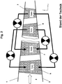
- the Fig. 1 shows a schematic representation of a fluid flow machine in the meridian view, here the example of a compressor consisting of an annular channel 2, which is bounded on the inside by a hub contour 3 and the outside by a housing contour 1, and with a number of rotor blade rows 6 and stator blade rows 7 within the annular channel 2 or main flow path is equipped. Between the blade rows 6, 7 exist bladder-free spaces. As shown by the large arrow, the turbomachine is flown from the left.
- the fluid return according to the invention relates to all areas of the side walls (hub 3 or housing 1) in which a blade end is provided without a relative movement between blade row and adjacent side wall, see marked areas.
- the Fig. 1 shows a schematic representation of a fluid flow machine in the meridian view, here the example of a compressor consisting of an annular channel 2, which is bounded on the inside by a hub contour 3 and the outside by a housing contour 1, and with a number of rotor blade rows 6 and stator blade rows
- FIG. 2 shows different types of fluid recirculation according to the prior art, from blade row to blade row, possibly between blade rows of the same or different type (rotor 6 or stator 7).
- the Fig. 3 schematically shows another category of fluid recirculation according to the prior art. These relate all to arrangements of rotors 6 with radial gap and relative movement between the rotor 6 and the surrounding Housing 1. Here, air is recirculated from a location above the rotor 6 to a location near the rotor leading edge.
- the Fig. 4 shows on the left side of the area of a blade end without a circumferential relative movement between the blade and the main flow path defining side wall.
- the fluid return according to the invention provides for the removal and supply of the fluid in fixed zones of the side wall in the region of the respective same blade row.
- the right side of the Fig. 4 shows the view ZZ, that is, a section through the row of blades with respect to the side wall and located between two blades blade passage in a plane defined by the circumferential direction u and the meridional direction m plane.
- the flow of the blade row is from the left.
- two fluid removal zones are defined, both of which are essentially supported on the profile pressure side: a comprehensive removal zone EA1, a further restricted withdrawal zone EA2 located within EA1, in which a removal is located according to the invention.
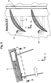
- the Fig. 5 shows how Fig. 4 on the left side, the area of a blade end without a circumferential relative movement between the blade and the side wall delimiting the main flow path.
- the right side of the Fig. 5 11 shows the view ZZ, ie the blade passage in the plane spanned by the circumferential direction u and the meridional direction m, now with two fluid supply zones, both of which are substantially supported on the profile suction side: a comprehensive feed zone IA1, and a further restricted feed zone located within IA1 IA2, in which a feed is located according to the invention.
- the Fig. 6 shows a scoop internal fluid return according to the invention.
- the left image side shows the arrangement in the meridional plane, spanned by the axial coordinate x and the radial coordinate r.
- a flow path is provided which allows a fluid return from a single opening in the removal zone according to the invention to a single opening in the feed zone according to the invention.
- the gearbox is shown in dashed lines, as it extends over a portion of the circumference, which is not fully representable in this view. Further features of the fluid recycling can be seen in the right part of the picture. There the arrangement is shown in the view ZZ.
- Fluid may enter from the main flowpath of the fluid flow machine into an orifice near the tread pressure side of a vane, is directed through a flow channel to the vicinity of the tread suction side of the adjacent vane, and there is supplied to the main flowpath substantially tangential to the sidewall.
- the removal opening has a larger cross-sectional area than the supply opening and in this way a continuous contraction of the return flow path is possible.
- fluid from the main flow path of the fluid flow machine enters an opening in the vicinity of the profile pressure side of a blade, is guided through a flow channel in the vicinity of the profile suction side of the same blade and fed there substantially tangentially to the side wall of the main flow path.
- the return flow path and the contour of the airfoil intersect.
- the center line of the passage between two adjacent blade profiles drawn is the Center line of the passage between two adjacent blade profiles drawn.
- the local removal opening and the local supply opening are arranged on different sides of the passage center line. Furthermore, it is particularly effective according to the invention if the area center of gravity of the fluid supply opening designated CGI is arranged in the meridional flow direction m upstream of the centroid of the fluid removal opening designated CGE. In addition, it is favorable according to the invention if the fluid supply opening is provided at least partially downstream of the leading edge plane LEP. As an embodiment of the invention exists, although no longer in Fig. 7 illustrated, at least one branch of the return flow path for supplying at least one further supply port.
- the Fig. 8 shows a not according to the invention similar arrangement of fluid recycling as Fig.
- the Fig. 9 shows a not according to the invention similar arrangement of fluid recycling as Fig. 8 but here removal is provided downstream of the trailing edge by means of a chamber extending over the entire circumference of the main flow path, from which individual channels for supplying a plurality of feed openings depart in the further return flow path.
- the Fig. 10 shows a further aspect of fluid recycling using the example of a rotor with blade platform and blade circumference feet.
- the rotor blades are mounted in a hub with the hub and blade platform forming a chamber outside the main flowpath.
- In the blade platform are each a removal opening and a
- Supply port provided, between which fluid can be replaced by the chamber below the platform.
- the supply port is formed here as a nozzle projecting into the main flow path.
- the Fig. 11 shows a further aspect of fluid recycling using the example of a stator with blade platform and blade circumference feet.
- the stator blades are mounted in a housing with the housing and paddle platform forming a chamber outside of the main flowpath.
- a removal opening and a supply opening are provided, between which fluid can be replaced by the chamber above the platform.
- the feed opening is here designed as a nozzle projecting into the main flow path.
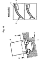
- the Fig. 12 shows a similar arrangement as Fig. 11 However, here is the removal opening formed as a projecting into the main flow path accumulation.
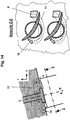
- the Fig. 13 also shows fluid recirculation on the stator now on both the housing side and the hub side of the main flow path.
- the stator On the hub side, the stator has an inner cover strip, which performs a rotating relative movement with respect to the rotor drum surrounded by it.
- a connection of extraction and supply ports can as in the FIGS. 6 to 9 shown to be provided as a number of individual channels, or as shown in FIG Fig. 13 shown, done by means of a circumferentially extending provided within the shroud chamber.
- the feed opening is here designed as a nozzle projecting into the main flow path, and the removal opening is designed as a congestion inlet projecting into the main flow path.
- the YY view shows one Blade section facing the shroud and fluid return ports.
- the Fig. 14 shows a further aspect of fluid recycling using the example of a rotatably mounted blade end.
- This may be a compound of rotor blade and hub, a compound of stator blade and housing or a combination of stator blade and inner shroud.
- the left part of the picture shows the fluid return in the area of the rotatable blade end. The fluid is passed from the removal opening to the supply opening, bypassing the adjustment axis of the blade. Both openings are exemplified here as flush with the main flow path.
- the view shown in the right half ZZ (blade section with a view of the main flow path wall and the turntable of the blades) shows a possible course of the return path.
- the blade profiles are shown here in the design position and would move over the openings during adjustment in partial load operation.
- the Fig. 15 shows a further aspect of fluid recycling using the example of a Verstellstators with inner shroud on the hub and rotatable fixation of the blades at both ends.
- the stator blades are mounted externally in a housing in which a flow chamber is formed, which connects the removal openings with the supply openings.
- Inside the stator blades are mounted in the shroud, in which also a flow chamber is provided, which connects the discharge openings with the supply openings. Further details of this exemplary arrangement are shown in the right half of FIG Fig. 15 ,
Landscapes
- Engineering & Computer Science (AREA)
- Mechanical Engineering (AREA)
- General Engineering & Computer Science (AREA)
- Structures Of Non-Positive Displacement Pumps (AREA)
- Turbine Rotor Nozzle Sealing (AREA)
Claims (10)
- Machine à écoulement avec laquelle, en service, du travail est appliqué à un fluide d'écoulement, dotée d'une voie d'écoulement (2) qui est délimitée par au moins une paroi sur laquelle est montée de manière fixe au moins une rangée d'aubes (6, 7),
sachant qu'au moins une ouverture de prélèvement de fluide (9) et au moins une ouverture d'alimentation en fluide (10) sont disposées dans la paroi, dans une zone d'une rangée d'aubes (6, 7), lesquelles ouvertures sont reliées par au moins une voie de recirculation de fluide (11), sachant que l'extension de l'ouverture d'alimentation en fluide (10) est inférieure, dans le sens circonférentiel, à l'écart entre deux aubes adjacentes,
sachant que l'ouverture de prélèvement de fluide (9) est disposée à l'intérieur d'une zone de prélèvement (EA1), sachant que la zone de prélèvement (EA1) est délimitée par:a.) une liaison rectiligne entre un point A situé à 0,5*CM en amont du plan de bord de fuite sur le côté d'aspiration du profil et un point de bord d'attaque du profil L opposé; CM désignant la longueur méridionale du profil d'aube sur la paroi latérale,b.) un côté de refoulement du profil PS,c.) une liaison rectiligne entre un point de bord de fuite T1 et un point B situé à 0,3*CM en aval de T1 dans la direction d'écoulement méridionale,d.) une liaison rectiligne entre le point B et un point C situé à la même coordonnée méridionale mais décalé de B du pas d'aubage SO dans le sens circonférentiel et en direction du côté d'aspiration adjacent,e.) une liaison rectiligne entre le point C et un point de bord de fuite T2 situé à cette cordonnée circonférentielle,f.) une partie arrière d'un côté d'aspiration du profil SS entre le point de bord de fuite T2 et le point A,sachant que l'ouverture de prélèvement de fluide (9) est disposée à l'intérieur d'une zone de prélèvement (EA2) qui est délimitée par:a.) une partie du côté de refoulement du profil dans la zone située entre le plan du bord de fuite et un plan situé à 0,75*CM en amont du plan du bord de fuite dans le sens méridional,b.) une liaison rectiligne entre les points D et E, sachant que le point D se situe à 0,75*CM en amont du plan du bord de fuite dans le sens méridional et est éloigné de 0,35*SO du côté de refoulement PS dans le sens circonférentiel et que le point E se situe dans le plan du bord de fuite et est éloigné de 0,5*SO du côté de refoulement PS dans le sens circonférentiel,c.) une liaison rectiligne entre le point D et le côté de refoulement du profil PS dans le sens circonférentiel,d.) une liaison rectiligne entre le point E et le point de bord de fuite T1 dans le sens circonférentiel,sachant que l'ouverture d'alimentation en fluide (10) est disposée à l'intérieur d'une zone d'alimentation (IA1) qui est délimitée par:a.) une liaison rectiligne entre un point de bord d'attaque L1 et un point F éloigné de celui-ci de 0,3*CM en amont dans le sens méridional; CM désignant la longueur méridionale du profil d'aube sur la paroi latérale,b.) une liaison rectiligne entre le point F et un point G situé à 0,3*CM en amont du point de bord d'attaque L2 dans le sens méridional,c.) une liaison rectiligne entre le point G et le point de bord d'attaque L2,d.) une liaison rectiligne entre le point de bord d'attaque L2 et un point H situé dans le plan du bord de fuite à une distance de 0,6*SO du côté d'aspiration du profil opposé,e.) une liaison rectiligne entre le point H et un point de bord de fuite T,f.) le côté d'aspiration du profil SS,et sachant que l'ouverture d'alimentation en fluide (10) est disposée à l'intérieur d'une zone d'alimentation (IA2) qui est délimitée par:a.) une liaison rectiligne entre le point de bord d'attaque L1 et le point F éloigné de celui-ci de 0,3*CM en amont dans le sens méridional; CM désignant la longueur méridionale du profil d'aube sur la paroi latérale,b.) une liaison rectiligne entre le point F et un point I situé à la même coordonnée méridionale et éloigné de F de 0,6*SO dans le sens circonférentiel,c.) une liaison rectiligne entre le point I et un point J disposé à 0,7*CM en aval du plan du bord d'attaque et décalé de 0,4*SO du côté de refoulement du profil, adjacent dans le sens circonférentiel, par rapport au point de bord de fuite T,d.) une liaison rectiligne entre le point J et le côté d'aspiration du profil dans le sens circonférentiel,e.) une partie du côté d'aspiration du profil dans la zone située entre le plan du bord d'attaque et un plan situé à 0,7*CM en aval du plan du bord d'attaque dans le sens méridional,caractérisée en ce que le centroïde de l'ouverture d'alimentation en fluide (10), observé dans le sens d'écoulement méridional est prévu en amont du centroïde de l'ouverture de prélèvement de fluide (9),
et que les ouvertures de prélèvement de fluide (9) et les ouvertures d'alimentation en fluide (10) prévues dans un passage d'aube sont disposées de différents côtés d'une ligne médiane du passage d'aube (8), sachant que du fluide est introduit par une seule ouverture de prélèvement de fluide (9) dans la voie de recirculation de fluide (11) respective qui est pourvue d'une ramification pour alimenter au moins une autre ouverture d'alimentation en fluide (10), sachant que l'ouverture de prélèvement de fluide (9) est conçue avec une surface de section transversale supérieure aux ouvertures d'alimentation en fluide (10) pour permettre une contraction continue de la voie de recirculation de fluide (11). - Machine à écoulement selon la revendication n° 1, caractérisée en ce que l'ouverture d'alimentation en fluide (10) est conçue pour une alimentation en fluide dirigée essentiellement tangentiellement à la paroi latérale de l'aube (6, 7).
- Machine à écoulement selon la revendication n° 1 ou n° 2, caractérisée en ce que la rangée d'aubes (6, 7) présente, dans au moins une de ses sections d'aube, une cambrure de profil avec une différence angulaire des tangentes appliquées à la ligne moyenne du profil sur le bord d'attaque et le bord de fuite d'au moins 35°.
- Machine à écoulement selon une des revendications n° 1 à n° 3, caractérisée en ce que l'ouverture d'alimentation en fluide (10) est prévue au moins partiellement en aval du plan du bord d'attaque de la rangée d'aubes (6, 7).
- Machine à écoulement selon une des revendications n° 1 à n° 4, caractérisée en ce qu'au moins une voie de recirculation de fluide (11) relie ladite une ouverture de prélèvement de fluide (9) à une ouverture d'alimentation en fluide (10) dans un autre passage d'aube.
- Machine à écoulement selon une des revendications n° 1 à n° 4, caractérisée en ce qu'au moins une voie de recirculation de fluide (11) relie ladite au moins une ouverture de prélèvement de fluide (9) à une ouverture d'alimentation en fluide (10) dans le meme passage d'aube.
- Machine à écoulement selon une des revendications n° 1 à n° 6, caractérisée en ce que la voie de recirculation de fluide (11) est disposée sur une rangée d'aubes de rotor (6) et/ ou une rangée d'aubes de stator (7), comprenant des aubes individuelles avec une plate-forme d'aube, sachant que le tambour de rotor (3) portant les aubes de rotor et/ ou le carter portant les aubes de stator et la plate-forme d'aube forment au moins un espace creux disposé à côté de la voie d'écoulement principale (2) et qu'au moins une ouverture d'alimentation en fluide (10) est prévue dans au moins une plate-forme d'aube, laquelle ouverture relie ledit au moins un espace creux à la voie d'écoulement principale (2).
- Machine à écoulement selon la revendication n° 7, caractérisée en ce qu'est formée dans au moins une plate-forme d'aube au moins une ouverture de prélèvement de fluide (9) qui relie la voie d'écoulement principale (2) audit au moins un espace creux.
- Machine à écoulement selon une des revendications n° 7 ou n° 8, caractérisée en ce qu'est formée entre au moins une plate-forme d'aube et le tambour de rotor (3) et/ ou le carter au moins une ouverture de prélèvement de fluide (9) qui relie la voie d'écoulement principale (2) audit au moins un espace creux.
- Machine à écoulement selon une des revendications précédentes, caractérisée en ce qu'au moins une aube de la rangée d'aubes (6, 7) est variable autour d'un axe de rotation d'aube, sachant qu'au moins un espace creux disposé à côté de la voie d'écoulement principale (2) et traversé par l'axe de rotation d'aube est formé dans le carter et/ ou le tambour de rotor (3), sachant que dans au moins un passage d'aube sont prévues au moins une ouverture d'alimentation en fluide (10) et/ ou au moins une ouverture de prélèvement de fluide (9) pour relier la voie d'écoulement principale (2) à l'espace creux.
Applications Claiming Priority (1)
| Application Number | Priority Date | Filing Date | Title |
|---|---|---|---|
| DE102008019603A DE102008019603A1 (de) | 2008-04-18 | 2008-04-18 | Strömungsmaschine mit schaufelreiheninterner Fluid-Rückführung |
Publications (3)
| Publication Number | Publication Date |
|---|---|
| EP2110559A2 EP2110559A2 (fr) | 2009-10-21 |
| EP2110559A3 EP2110559A3 (fr) | 2015-03-25 |
| EP2110559B1 true EP2110559B1 (fr) | 2018-12-12 |
Family
ID=40474926
Family Applications (1)
| Application Number | Title | Priority Date | Filing Date |
|---|---|---|---|
| EP09003693.0A Ceased EP2110559B1 (fr) | 2008-04-18 | 2009-03-13 | Turbomachine avec réinjection de fluide pour influencer la couche limite |
Country Status (3)
| Country | Link |
|---|---|
| US (1) | US8043046B2 (fr) |
| EP (1) | EP2110559B1 (fr) |
| DE (1) | DE102008019603A1 (fr) |
Cited By (1)
| Publication number | Priority date | Publication date | Assignee | Title |
|---|---|---|---|---|
| FR3152831A1 (fr) * | 2023-09-11 | 2025-03-14 | Safran Aircraft Engines | Aubage de turbomachine |
Families Citing this family (37)
| Publication number | Priority date | Publication date | Assignee | Title |
|---|---|---|---|---|
| DE102008011746A1 (de) * | 2008-02-28 | 2009-09-03 | Mtu Aero Engines Gmbh | Vorrichtung und Verfahren zur Umleitung eines Leckagestroms |
| FR2931886B1 (fr) * | 2008-05-29 | 2011-10-14 | Snecma | Collecteur d'air dans une turbomachine. |
| DE102008029605A1 (de) * | 2008-06-23 | 2009-12-24 | Rolls-Royce Deutschland Ltd & Co Kg | Schaufeldeckband mit Durchlass |
| DE102008036294A1 (de) * | 2008-08-04 | 2010-02-11 | Mtu Aero Engines Gmbh | Axialverdichter mit Verdichtergitter |
| DE102008060424A1 (de) * | 2008-12-04 | 2010-06-10 | Rolls-Royce Deutschland Ltd & Co Kg | Strömungsmaschine mit Seitenwand-Grenzschicht-Barriere |
| US9068507B2 (en) * | 2011-11-16 | 2015-06-30 | General Electric Company | Compressor having purge circuit and method of purging |
| CN102556345B (zh) * | 2012-01-18 | 2016-04-13 | 朱晓义 | 飞机动力装置 |
| KR20170120202A (ko) | 2013-01-23 | 2017-10-30 | 컨셉츠 이티아이 인코포레이티드 | 터보머신들의 인접한 블레이드 요소들의 흐름장들의 결합을 가하는 구조들 및 방법들, 그리고 그들을 포함하는 터보머신들 |
| DE102013210169A1 (de) * | 2013-05-31 | 2014-12-04 | Rolls-Royce Deutschland Ltd & Co Kg | Strukturbaugruppe für eine Strömungsmaschine |
| DE102013210167A1 (de) * | 2013-05-31 | 2014-12-04 | Rolls-Royce Deutschland Ltd & Co Kg | Strukturbaugruppe für eine Strömungsmaschine |
| DE102013222514A1 (de) | 2013-11-06 | 2015-05-07 | MTU Aero Engines AG | Dichtungsanordnung für eine Strömungsmaschine |
| EP2871368B1 (fr) * | 2013-11-12 | 2018-09-12 | MTU Aero Engines GmbH | Compresseur de turbine à gaz |
| EP2881548B1 (fr) * | 2013-12-09 | 2018-08-15 | MTU Aero Engines GmbH | Compresseur de turbine à gaz |
| US9845810B2 (en) | 2014-06-24 | 2017-12-19 | Concepts Nrec, Llc | Flow control structures for turbomachines and methods of designing the same |
| DE102015110249A1 (de) * | 2015-06-25 | 2017-01-12 | Rolls-Royce Deutschland Ltd & Co Kg | Statorvorrichtung für eine Strömungsmaschine mit einer Gehäuseeinrichtung und mehreren Leitschaufeln |
| DE102015110252A1 (de) * | 2015-06-25 | 2016-12-29 | Rolls-Royce Deutschland Ltd & Co Kg | Statorvorrichtung für eine Strömungsmaschine mit einer Gehäuseeinrichtung und mehreren Leitschaufeln |
| DE102015110250A1 (de) * | 2015-06-25 | 2016-12-29 | Rolls-Royce Deutschland Ltd & Co Kg | Statorvorrichtung für eine Strömungsmaschine mit einer Gehäuseeinrichtung und mehreren Leitschaufeln |
| US10041500B2 (en) * | 2015-12-08 | 2018-08-07 | General Electric Company | Venturi effect endwall treatment |
| CN107150788A (zh) * | 2017-04-26 | 2017-09-12 | 朱晓义 | 一种产生更大升力的固定翼飞行器 |
| DE102017118950A1 (de) * | 2017-08-18 | 2019-02-21 | Abb Turbo Systems Ag | Diffusor für einen Radialverdichter |
| FR3082558B1 (fr) * | 2018-06-15 | 2021-09-17 | Safran Aircraft Engines | Distributeur de turbine pour turbomachine, comprenant un systeme passif de reintroduction de gaz de fuite dans une veine d'ecoulement des gaz |
| FR3084395B1 (fr) * | 2018-07-24 | 2020-10-30 | Safran Aircraft Engines | Ailettes entrefer pour compresseur de turbomachine |
| US10876549B2 (en) | 2019-04-05 | 2020-12-29 | Pratt & Whitney Canada Corp. | Tandem stators with flow recirculation conduit |
| FR3107917B1 (fr) * | 2020-03-04 | 2022-09-09 | Safran | Carter de roue mobile pour turbomachine |
| FR3109959B1 (fr) * | 2020-05-06 | 2022-04-22 | Safran Helicopter Engines | Compresseur de turbomachine comportant une paroi fixe pourvue d’un traitement de forme |
| CN116194675A (zh) | 2020-08-07 | 2023-05-30 | 概创机械设计有限责任公司 | 用于增强性能的流量控制结构及结合有该流量控制结构的透平机 |
| US11732612B2 (en) | 2021-12-22 | 2023-08-22 | Rolls-Royce North American Technologies Inc. | Turbine engine fan track liner with tip injection air recirculation passage |
| US11946379B2 (en) | 2021-12-22 | 2024-04-02 | Rolls-Royce North American Technologies Inc. | Turbine engine fan case with manifolded tip injection air recirculation passages |
| US11702945B2 (en) | 2021-12-22 | 2023-07-18 | Rolls-Royce North American Technologies Inc. | Turbine engine fan case with tip injection air recirculation passage |
| FR3133063B1 (fr) * | 2022-02-25 | 2024-08-02 | Safran Aircraft Engines | Aubage de turbomachine, comprenant une pale et une plateforme qui présente un canal interne d’aspiration et d’éjection de flux |
| US12146413B1 (en) | 2023-12-12 | 2024-11-19 | Rolls-Royce North American Technologies Inc. | Circumferentially variable flow control in fan outlet guide vane assemblies for distortion management and stall margin in gas turbine engines |
| US12258870B1 (en) | 2024-03-08 | 2025-03-25 | Rolls-Royce North American Technologies Inc. | Adjustable fan track liner with slotted array active fan tip treatment for distortion tolerance |
| US12286936B1 (en) | 2024-05-09 | 2025-04-29 | Rolls-Royce North American Technologies Inc. | Adjustable fan track liner with groove array active fan tip treatment for distortion tolerance |
| US12209541B1 (en) | 2024-05-09 | 2025-01-28 | Rolls-Royce North American Technologies Inc. | Adjustable fan track liner with dual slotted array active fan tip treatment for distortion tolerance |
| US12215712B1 (en) | 2024-05-09 | 2025-02-04 | Rolls-Royce North American Technologies Inc. | Adjustable fan track liner with dual grooved array active fan tip treatment for distortion tolerance |
| US12209502B1 (en) | 2024-06-28 | 2025-01-28 | Rolls-Royce North American Technologies Inc. | Active fan tip treatment using rotating drum array with axial channels in fan track liner for distortion tolerance |
| US12168983B1 (en) | 2024-06-28 | 2024-12-17 | Rolls-Royce North American Technologies Inc. | Active fan tip treatment using rotating drum array in fan track liner with axial and circumferential channels for distortion tolerance |
Family Cites Families (15)
| Publication number | Priority date | Publication date | Assignee | Title |
|---|---|---|---|---|
| CH204331A (de) * | 1937-02-24 | 1939-04-30 | Rheinmetall Borsig Ag | Einrichtung zur Verhinderung der Strahlablösung bei Turboverdichtern. |
| JPS5254809A (en) * | 1975-10-31 | 1977-05-04 | Hitachi Ltd | Axial-flow fluid machine construction |
| KR100198721B1 (ko) * | 1991-01-30 | 1999-06-15 | 레비스 스테픈 이 | 개선된 케이스를 갖는 가스 터어빈 엔진 |
| US5431533A (en) * | 1993-10-15 | 1995-07-11 | United Technologies Corporation | Active vaned passage casing treatment |
| US5474417A (en) * | 1994-12-29 | 1995-12-12 | United Technologies Corporation | Cast casing treatment for compressor blades |
| US5607284A (en) * | 1994-12-29 | 1997-03-04 | United Technologies Corporation | Baffled passage casing treatment for compressor blades |
| US6220012B1 (en) * | 1999-05-10 | 2001-04-24 | General Electric Company | Booster recirculation passageway and methods for recirculating air |
| US6585479B2 (en) * | 2001-08-14 | 2003-07-01 | United Technologies Corporation | Casing treatment for compressors |
| DE10233032A1 (de) * | 2002-07-20 | 2004-01-29 | Rolls-Royce Deutschland Ltd & Co Kg | Strömungsarbeitsmaschine mit integriertem Fluidzirkulationssystem |
| CA2496543C (fr) * | 2002-08-23 | 2010-08-10 | Mtu Aero Engines Gmbh | Structure de recirculation d'un turbocompresseur |
| DE10355240A1 (de) * | 2003-11-26 | 2005-07-07 | Rolls-Royce Deutschland Ltd & Co Kg | Strömungsarbeitsmaschine mit Fluidentnahme |
| GB2413158B (en) * | 2004-04-13 | 2006-08-16 | Rolls Royce Plc | Flow control arrangement |
| DE102004030597A1 (de) | 2004-06-24 | 2006-01-26 | Rolls-Royce Deutschland Ltd & Co Kg | Strömungsarbeitsmaschine mit Aussenradstrahlerzeugung am Stator |
| DE102004055439A1 (de) * | 2004-11-17 | 2006-05-24 | Rolls-Royce Deutschland Ltd & Co Kg | Strömungsarbeitsmaschine mit dynamischer Strömungsbeeinflussung |
| DE102007012119A1 (de) * | 2007-03-13 | 2008-09-18 | Rolls-Royce Deutschland Ltd & Co Kg | Drosselgradabhängige Schaufelverstellung bei Strömungsarbeitsmaschinen |
-
2008
- 2008-04-18 DE DE102008019603A patent/DE102008019603A1/de not_active Withdrawn
-
2009
- 2009-03-13 EP EP09003693.0A patent/EP2110559B1/fr not_active Ceased
- 2009-04-17 US US12/385,767 patent/US8043046B2/en active Active
Non-Patent Citations (1)
| Title |
|---|
| None * |
Cited By (2)
| Publication number | Priority date | Publication date | Assignee | Title |
|---|---|---|---|---|
| FR3152831A1 (fr) * | 2023-09-11 | 2025-03-14 | Safran Aircraft Engines | Aubage de turbomachine |
| WO2025056841A1 (fr) * | 2023-09-11 | 2025-03-20 | Safran Aircraft Engines | Aubage de turbomachine |
Also Published As
| Publication number | Publication date |
|---|---|
| US20090263233A1 (en) | 2009-10-22 |
| US8043046B2 (en) | 2011-10-25 |
| DE102008019603A1 (de) | 2009-10-22 |
| EP2110559A2 (fr) | 2009-10-21 |
| EP2110559A3 (fr) | 2015-03-25 |
Similar Documents
| Publication | Publication Date | Title |
|---|---|---|
| EP2110559B1 (fr) | Turbomachine avec réinjection de fluide pour influencer la couche limite | |
| EP1382855B1 (fr) | Turbomachine avec système de recirculation de fluide intégré | |
| EP1659293B1 (fr) | Turbomachine | |
| EP2138727B1 (fr) | Bande de recouvrement d'aube dotée d'un passage | |
| EP2108784B1 (fr) | Turbomachine dotée d'un composant d'injecteur de fluide | |
| EP2025945B1 (fr) | Machine de traitement des écoulements dotée d'un creux de paroi de canal de ceinture | |
| EP2096316B1 (fr) | Structuration de boîtier pour compresseur axial dans la zone du moyeu | |
| EP1609999B1 (fr) | Turbo machine | |
| DE102007056953B4 (de) | Strömungsarbeitsmaschine mit Ringkanalwandausnehmung | |
| EP2003292B1 (fr) | Machine de travail fluidique avec virole d'aube dotée d'un rebord | |
| EP2151582A2 (fr) | Machine de traitement des écoulements | |
| EP2228542B1 (fr) | Turbo compresseur ou pompe avec injection de fluide pour influencer la couche limite | |
| EP2808559B1 (fr) | Ensemble structurel pour une turbomachine | |
| EP2180193B1 (fr) | Turbomachine dotée d'un moyen pour énergiser des bords proches du côté aspirant | |
| EP2009239A2 (fr) | Aube dotée d'une production de jets tangentiels sur le profil | |
| EP2993357B1 (fr) | Étage de compresseur radial | |
| EP2180195A2 (fr) | Turbomachine avec contrôle du jeu des aubes | |
| EP2808556B1 (fr) | Ensemble structurel pour une turbomachine | |
| CH710476A2 (de) | Verdichter mit einer Axialverdichterendwandeinrichtung zur Steuerung der Leckageströmung in dieser. | |
| EP1998049A2 (fr) | Aube de machine de travail d'écoulement doté d'une conception à plusieurs profiles | |
| EP2913480B1 (fr) | Aubes en tandem d'une turbomachine | |
| EP3121373A1 (fr) | Roue de turbine refroidie, plus particulièrement pour un réacteur | |
| EP3078804A1 (fr) | Agencement virole pour une rangée d'aubes de rotor ou stator et turbine associée | |
| EP2808557A1 (fr) | Ensemble structurel pour une turbomachine |
Legal Events
| Date | Code | Title | Description |
|---|---|---|---|
| PUAI | Public reference made under article 153(3) epc to a published international application that has entered the european phase |
Free format text: ORIGINAL CODE: 0009012 |
|
| AK | Designated contracting states |
Kind code of ref document: A2 Designated state(s): AT BE BG CH CY CZ DE DK EE ES FI FR GB GR HR HU IE IS IT LI LT LU LV MC MK MT NL NO PL PT RO SE SI SK TR |
|
| AX | Request for extension of the european patent |
Extension state: AL BA RS |
|
| PUAL | Search report despatched |
Free format text: ORIGINAL CODE: 0009013 |
|
| AK | Designated contracting states |
Kind code of ref document: A3 Designated state(s): AT BE BG CH CY CZ DE DK EE ES FI FR GB GR HR HU IE IS IT LI LT LU LV MC MK MT NL NO PL PT RO SE SI SK TR |
|
| AX | Request for extension of the european patent |
Extension state: AL BA RS |
|
| RIC1 | Information provided on ipc code assigned before grant |
Ipc: F04D 29/32 20060101ALI20150217BHEP Ipc: F04D 29/68 20060101ALI20150217BHEP Ipc: F04D 29/52 20060101AFI20150217BHEP |
|
| 17P | Request for examination filed |
Effective date: 20150421 |
|
| RBV | Designated contracting states (corrected) |
Designated state(s): AT BE BG CH CY CZ DE DK EE ES FI FR GB GR HR HU IE IS IT LI LT LU LV MC MK MT NL NO PL PT RO SE SI SK TR |
|
| AKX | Designation fees paid |
Designated state(s): DE FR GB |
|
| AXX | Extension fees paid |
Extension state: BA Extension state: AL Extension state: RS |
|
| 17Q | First examination report despatched |
Effective date: 20160407 |
|
| GRAP | Despatch of communication of intention to grant a patent |
Free format text: ORIGINAL CODE: EPIDOSNIGR1 |
|
| INTG | Intention to grant announced |
Effective date: 20180712 |
|
| GRAS | Grant fee paid |
Free format text: ORIGINAL CODE: EPIDOSNIGR3 |
|
| GRAA | (expected) grant |
Free format text: ORIGINAL CODE: 0009210 |
|
| AK | Designated contracting states |
Kind code of ref document: B1 Designated state(s): DE FR GB |
|
| REG | Reference to a national code |
Ref country code: GB Ref legal event code: FG4D Free format text: NOT ENGLISH |
|
| RIN1 | Information on inventor provided before grant (corrected) |
Inventor name: GUEMMER, VOLKER, DR. |
|
| REG | Reference to a national code |
Ref country code: DE Ref legal event code: R096 Ref document number: 502009015503 Country of ref document: DE |
|
| REG | Reference to a national code |
Ref country code: DE Ref legal event code: R097 Ref document number: 502009015503 Country of ref document: DE |
|
| PLBE | No opposition filed within time limit |
Free format text: ORIGINAL CODE: 0009261 |
|
| STAA | Information on the status of an ep patent application or granted ep patent |
Free format text: STATUS: NO OPPOSITION FILED WITHIN TIME LIMIT |
|
| 26N | No opposition filed |
Effective date: 20190913 |
|
| PGFP | Annual fee paid to national office [announced via postgrant information from national office to epo] |
Ref country code: GB Payment date: 20200327 Year of fee payment: 12 |
|
| GBPC | Gb: european patent ceased through non-payment of renewal fee |
Effective date: 20210313 |
|
| PG25 | Lapsed in a contracting state [announced via postgrant information from national office to epo] |
Ref country code: GB Free format text: LAPSE BECAUSE OF NON-PAYMENT OF DUE FEES Effective date: 20210313 |
|
| PGFP | Annual fee paid to national office [announced via postgrant information from national office to epo] |
Ref country code: FR Payment date: 20230323 Year of fee payment: 15 |
|
| PGFP | Annual fee paid to national office [announced via postgrant information from national office to epo] |
Ref country code: DE Payment date: 20230328 Year of fee payment: 15 |
|
| P01 | Opt-out of the competence of the unified patent court (upc) registered |
Effective date: 20230528 |
|
| REG | Reference to a national code |
Ref country code: DE Ref legal event code: R119 Ref document number: 502009015503 Country of ref document: DE |
|
| PG25 | Lapsed in a contracting state [announced via postgrant information from national office to epo] |
Ref country code: DE Free format text: LAPSE BECAUSE OF NON-PAYMENT OF DUE FEES Effective date: 20241001 |
|
| PG25 | Lapsed in a contracting state [announced via postgrant information from national office to epo] |
Ref country code: FR Free format text: LAPSE BECAUSE OF NON-PAYMENT OF DUE FEES Effective date: 20240331 |
|
| PG25 | Lapsed in a contracting state [announced via postgrant information from national office to epo] |
Ref country code: FR Free format text: LAPSE BECAUSE OF NON-PAYMENT OF DUE FEES Effective date: 20240331 Ref country code: DE Free format text: LAPSE BECAUSE OF NON-PAYMENT OF DUE FEES Effective date: 20241001 |