EP2808557A1 - Ensemble structurel pour une turbomachine - Google Patents
Ensemble structurel pour une turbomachine Download PDFInfo
- Publication number
- EP2808557A1 EP2808557A1 EP14170060.9A EP14170060A EP2808557A1 EP 2808557 A1 EP2808557 A1 EP 2808557A1 EP 14170060 A EP14170060 A EP 14170060A EP 2808557 A1 EP2808557 A1 EP 2808557A1
- Authority
- EP
- European Patent Office
- Prior art keywords
- flow channel
- secondary flow
- flow path
- insert
- support member
- Prior art date
- Legal status (The legal status is an assumption and is not a legal conclusion. Google has not performed a legal analysis and makes no representation as to the accuracy of the status listed.)
- Withdrawn
Links
- 238000003780 insertion Methods 0.000 abstract description 2
- 230000037431 insertion Effects 0.000 abstract description 2
- 239000012530 fluid Substances 0.000 description 23
- 238000011282 treatment Methods 0.000 description 7
- 239000000243 solution Substances 0.000 description 6
- 238000004519 manufacturing process Methods 0.000 description 3
- 230000000712 assembly Effects 0.000 description 2
- 238000000429 assembly Methods 0.000 description 2
- 238000002347 injection Methods 0.000 description 2
- 239000007924 injection Substances 0.000 description 2
- 238000011144 upstream manufacturing Methods 0.000 description 2
- 238000005266 casting Methods 0.000 description 1
- 238000009434 installation Methods 0.000 description 1
- 239000007788 liquid Substances 0.000 description 1
- 238000003754 machining Methods 0.000 description 1
- 238000003801 milling Methods 0.000 description 1
- 230000000149 penetrating effect Effects 0.000 description 1
- 238000000926 separation method Methods 0.000 description 1
- 238000007493 shaping process Methods 0.000 description 1
- 238000005245 sintering Methods 0.000 description 1
Images


Classifications
-
- F—MECHANICAL ENGINEERING; LIGHTING; HEATING; WEAPONS; BLASTING
- F04—POSITIVE - DISPLACEMENT MACHINES FOR LIQUIDS; PUMPS FOR LIQUIDS OR ELASTIC FLUIDS
- F04D—NON-POSITIVE-DISPLACEMENT PUMPS
- F04D29/00—Details, component parts, or accessories
- F04D29/66—Combating cavitation, whirls, noise, vibration or the like; Balancing
- F04D29/68—Combating cavitation, whirls, noise, vibration or the like; Balancing by influencing boundary layers
- F04D29/681—Combating cavitation, whirls, noise, vibration or the like; Balancing by influencing boundary layers especially adapted for elastic fluid pumps
-
- F—MECHANICAL ENGINEERING; LIGHTING; HEATING; WEAPONS; BLASTING
- F04—POSITIVE - DISPLACEMENT MACHINES FOR LIQUIDS; PUMPS FOR LIQUIDS OR ELASTIC FLUIDS
- F04D—NON-POSITIVE-DISPLACEMENT PUMPS
- F04D29/00—Details, component parts, or accessories
- F04D29/08—Sealings
- F04D29/16—Sealings between pressure and suction sides
- F04D29/161—Sealings between pressure and suction sides especially adapted for elastic fluid pumps
-
- F—MECHANICAL ENGINEERING; LIGHTING; HEATING; WEAPONS; BLASTING
- F04—POSITIVE - DISPLACEMENT MACHINES FOR LIQUIDS; PUMPS FOR LIQUIDS OR ELASTIC FLUIDS
- F04D—NON-POSITIVE-DISPLACEMENT PUMPS
- F04D29/00—Details, component parts, or accessories
- F04D29/40—Casings; Connections of working fluid
- F04D29/52—Casings; Connections of working fluid for axial pumps
- F04D29/522—Casings; Connections of working fluid for axial pumps especially adapted for elastic fluid pumps
- F04D29/526—Details of the casing section radially opposing blade tips
-
- F—MECHANICAL ENGINEERING; LIGHTING; HEATING; WEAPONS; BLASTING
- F04—POSITIVE - DISPLACEMENT MACHINES FOR LIQUIDS; PUMPS FOR LIQUIDS OR ELASTIC FLUIDS
- F04D—NON-POSITIVE-DISPLACEMENT PUMPS
- F04D29/00—Details, component parts, or accessories
- F04D29/40—Casings; Connections of working fluid
- F04D29/52—Casings; Connections of working fluid for axial pumps
- F04D29/54—Fluid-guiding means, e.g. diffusers
- F04D29/541—Specially adapted for elastic fluid pumps
-
- F—MECHANICAL ENGINEERING; LIGHTING; HEATING; WEAPONS; BLASTING
- F04—POSITIVE - DISPLACEMENT MACHINES FOR LIQUIDS; PUMPS FOR LIQUIDS OR ELASTIC FLUIDS
- F04D—NON-POSITIVE-DISPLACEMENT PUMPS
- F04D29/00—Details, component parts, or accessories
- F04D29/66—Combating cavitation, whirls, noise, vibration or the like; Balancing
- F04D29/68—Combating cavitation, whirls, noise, vibration or the like; Balancing by influencing boundary layers
- F04D29/681—Combating cavitation, whirls, noise, vibration or the like; Balancing by influencing boundary layers especially adapted for elastic fluid pumps
- F04D29/685—Inducing localised fluid recirculation in the stator-rotor interface
Definitions
- the invention relates to a structural assembly for a turbomachine according to the preamble of patent claim 1.
- turbomachines in particular of fluid flow machines such as fans, compressors, pumps and fans, is limited by the growth and separation of boundary layers in the rotor and stator tip region near the housing or hub wall. In the case of blade rows with a running gap, this leads to high secondary losses and possibly to the occurrence of operational instabilities at higher loads.
- casing treatments As a countermeasure, it is known to use so-called casing treatments.
- the simplest form of casing treatments are circumferential grooves with a rectangular or parallelogram-shaped cross-section, as used, for example, in US Pat EP 0 754 864 A1 are disclosed.
- Other solutions provide for rows of slots or openings in the housing, the individual slots / openings being oriented substantially in the flow direction and having a slender shape with a small extension viewed in the circumferential direction of the machine. Such solutions are for example in the DE 101 35 003 C1 disclosed.
- a fluid flow machine which forms at least one secondary flow channel in the area of the blade leading edge in a main flow path boundary, which connects two openings arranged on the main flow path boundary.
- Each secondary flow channel in each case connects a removal opening with a supply opening provided further upstream.
- a spatially compact and robust structural design is to be provided.
- the structural assembly has at least one support member and at least one insert component.
- a circumferentially extending structure is formed, which receives along the circumference at least one insert member or holds.
- Each insert member forms with at least a portion of its surfaces at least a portion of the main flow path boundary.
- each secondary flow channel is co-delimited along at least part of its course by surfaces of at least two components of the structural assembly, such that in the assembled state each of the secondary flow channels is completely surrounded by these surfaces.
- the solution according to the invention is therefore based on the idea of providing secondary flow channels, which are formed together at least along a subsection through the surfaces of several components of the structural subassembly, i. the secondary flow channels are provided at least in sections at the interfaces between adjacent components of the structural assembly, for example by surface structuring of at least one of these boundary surfaces.
- the invention thus contemplates a portion of the main flowpath of a turbomachine, in the region of a free end and a nip row of blades, in which a series of circumferentially distributed secondary flow channels are provided.
- the course of the secondary flow channels can each be spatially complex.
- a structural assembly is provided for structurally implementing said secondary flow channels.
- An embodiment of the invention provides that at least one secondary flow channel along at least part of its course is formed by surfaces of a support component and an insert component.
- the structural assembly may additionally comprise at least one auxiliary component, which also forms surfaces having a Limit secondary flow channel along at least part of its course. It can be provided that at least one auxiliary component is arranged in the axial direction in front of or behind an insert component and forms a portion of the secondary flow channel together with surfaces of the insert component. In particular, two auxiliary components can be arranged in the axial direction in front of and behind the insert component, which form two sections of the secondary flow channel.
- an embodiment of the invention provides that the circumferentially extending structure, which receives or holds an insert member is a recess, a projection or a web.
- the insert member is inserted into a recess of the support member in the radial direction or inserted in the axial direction, or attached to a projection or web of the support member or pushed onto such.
- the support member is designed as a ring housing or as a half shell housing a turbomachine and encases this at least one further component of the structural assembly from the outside. It can also be provided that the support member is annular or semi-annular manner formed on the hub of a turbomachine and supports at least one further component of the structural assembly from the inside.
- the at least one insert component and / or the at least one auxiliary component of the assembly may be formed as a whole ring or as a ring sector. Also, both the support member and the insert member may be formed as a ring housing.
- the at least one secondary flow channel is predominantly formed in the insert component, for example by channels or longitudinal grooves formed on a convex outer surface of the insert component, wherein the support member completes the secondary flow channel through at least one of its surfaces.
- the surface of the support member delimiting the secondary flow channel is formed as part of a plane, a cone, a circular cylinder or a cylinder and in this way the sections of the at least one secondary flow channel which are still open in the insert component are flush closed.
- the secondary flow channel is predominantly formed in the support component, for example by channels or longitudinal grooves formed on a concave outer surface of the support member, wherein the insert member through at least one of its surfaces the secondary flow channel completed.
- the areas of the insert component delimiting the secondary flow channel are formed as part of a plane, a cone, a circular cylinder or a cylinder and in this way the sections of the at least one secondary flow channel that are still open in the support component are flush closed.
- the insert component in the meridian view is surrounded by the support component to a predominant proportion of its sides which do not face the main flow path.
- the insert component is in terms of shape and surface quality in one embodiment of the invention such that it can be inserted in the axial direction of the turbomachine in the support member. This allows for easy installation. It can be provided for positioning and connection of support member and insert member that the support member and the insert member are connected to a common flange. It can also be provided that the support member forms an annular projection, on which the insert member is pushed in the axial direction.
- An embodiment of the invention provides that the division of the wetted surfaces of the secondary flow channel between the support member and the insert member is selected such that a central portion of the secondary flow duct extending in the meridian view substantially along the direction of the main flow path boundary is provided in the support member is and is covered with a surface of the insert member, while at least one provided in the region of the openings at the Stilströmungspfadberandung portion of the secondary flow channel is provided entirely with all wetted surfaces in the insert component.
- a further embodiment of the invention provides that an exchangeable plug is provided, which penetrates the support member and / or the insert member from the side facing away from the main flow path side, wherein the plug harbors a portion of a secondary flow channel such that it does not react with the rest of the in the plug extending portion of the secondary flow channel connects.
- the top surface of the replaceable plug forms part of the main flow path boundary and formed in the top surface of one of the openings of the secondary flow channel. The plug is introduced in the radial direction and ends with its end face on the main flow path boundary.
- a further embodiment of the invention provides that a middle section of the secondary flow channel, which, when viewed in the meridian view, extends substantially along the direction of the main flow path boundary, is provided individually or jointly in the support component and / or the insert component. Furthermore, in the region of the openings at the main flow path boundary, i. provided at the areas near the opening, at least a portion of the secondary flow channel, which is formed by a combination of surfaces of the insert member and surfaces of at least one auxiliary component.
- the support member and the insert member thus form according to this embodiment, only a portion of the secondary flow channel.
- Other sections are formed by means of at least one auxiliary component. It can be provided that the surfaces of the insert component and the surfaces of the at least one auxiliary component have a locally strongly curved course and thus form a strongly curved secondary flow channel in this area.
- a further embodiment of the invention provides that an insert component and at least one auxiliary component are brought into contact with each other substantially along the direction of the main flow path boundary. It can be provided that an insert component is brought into contact with two auxiliary components substantially along the direction of the main flow path boundary and is arranged substantially between the auxiliary components. It can further be provided that at least one of the auxiliary components can be pushed together with the insert component into the support component in the axial direction.
- a further embodiment of the invention provides that an auxiliary component on the side facing the insert component has a constant in the circumferential direction of the turbomachine contour profile, wherein both a Detailberandungs Type at least one secondary flow channel and contact surfaces are provided to the insert component by the contour profile. It can also be provided that an auxiliary component has, on the sides facing the insert component, a contour contoured in the circumferential direction of the turbomachine, wherein a partial boundary surface of at least one secondary flow channel and contact surfaces with the insert component are created by the contoured form.
- a further embodiment of the invention provides that an auxiliary component and an insert component interlock and / or that an auxiliary component and an insert component are entangled along the circumference and / or that the auxiliary member has locally at the periphery at least one projection which engages in the insert member and forms the Crystalbandungs Colour at least one secondary flow channel.
- a further embodiment of the invention provides that, when viewing a secondary flow channel section in the region of the openings at the main flow path boundary in the meridian view, there is one continuous convex curve and one continuous curve with a continuous concave curvature along the inner contour of the secondary flow channel, the lines in Substantially opposed within a secondary flow channel section. It can be provided that at least a portion of the convex polyline listened to the insert component and at least a portion of the concave polyline listened to an auxiliary component.
- a further embodiment of the invention provides that an auxiliary component and an insert component are formed as at least part of a ring and engage in the assembled state with forward and backward jumps alternately provided on the circumference.
- the insert component is produced, for example, with the aid of a casting, sintering or print production method.
- the present invention relates generally to structural assemblies for turbomachinery such as turbines, and more particularly to fluid flow machines such as fans, compressors, pumps and fans, in both axial, semi-axial and radial designs.
- the working medium or fluid may be gaseous or liquid.
- the turbomachine may include one or more stages each having a rotor and a stator. In some cases, the stage is formed only by a rotor.
- the rotor of a turbomachine in which a structural assembly according to the invention is used, consists of a number of blades, which are connected to the rotating shaft of the turbomachine and deliver energy to the working fluid in the case of the fluid flow machine.
- the rotor can be designed with or without shroud on the outer blade end.
- the stator of a turbomachine in which a structural assembly according to the invention is used, consists of a number of stationary blades, which can be designed on the hub side as the housing side with a fixed or free blade end.
- the rotor drum and the blading are usually surrounded by a housing. In other cases, z. As in propellers or propellers, no housing exists.
- a turbomachine in which a structural assembly according to the invention is used, can also have a stator in front of the first rotor, a so-called leading wheel. At least one stator or Vorleitrad - may be rotatably mounted - deviating from an immovable fixation - to change the angle of attack can. An adjustment is made for example by a spindle accessible from outside the annular channel.
- a turbomachine in which a structural assembly according to the invention is used, have at least one row of adjustable rotors.
- a turbomachine in which a structural assembly according to the invention is used in multi-stage have two opposing waves, so that the rotor blade rows change the direction of rotation from stage to stage. There are no stators between successive rotors.
- a turbomachine in which a structural assembly according to the invention is used have a bypass configuration such that a single-flow annular channel behind a certain row of blades divides into two concentric annular channels, which in turn accommodate at least one more row of blades.
- turbomachine in which a structural assembly according to the invention is used, it is, for example, a jet engine, in particular a turbofan engine.
- the structural assembly is formed, for example, in the region of a compressor of a jet engine or turbofan engine.
- the invention further relates to a fluid flow machine with a structural assembly according to the invention.
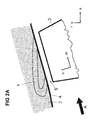
- the Fig. 2A shows an arrangement of a blade row 3 with free end and running gap 5 in the meridian plane formed by the axial direction x and the radial direction r.
- Run nip 5 separates the blade tip from a component 2 belonging to the main flow path at the hub or housing of the fluid flow machine.
- the component 2 forms a main flow path boundary 4 toward the main flow path.
- the main flow direction in the main flow path is indicated by an arrow A. Upstream and / or downstream of the row of blades 3 with running gap, further rows of blades may be located.
- a number of secondary flow channels 1 distributed on the circumference are provided in the region of the running gap 5, each of which forms an opening at its ends (feed opening and removal opening).
- Fig. 2A shows the outline or the projection of a single secondary flow channel 1 in the meridian plane (xr).
- xr meridian plane
- each channel 1 has a three-dimensional spatially twisted course, which in the Fig. 2B is shown by way of example.
- cross-sectional shape of the secondary flow channels 1 in the Fig. 2B merely exemplified as rectangular.
- the cross section of the secondary flow channels 1 may be formed in other embodiments without corners, in particular circular or elliptical.
- FIG. 3A shows a structural assembly according to the invention in the region of a row of blades with running gap in the meridian view (xr).
- the main flow direction is indicated by an arrow A.
- the blade row is no longer shown in favor of a simpler representation.
- At least one secondary flow channel 1 is formed, which has two openings 111, 112 in the main flow path boundary 4 and is connected via this to the main flow path.
- the secondary flow channel 11 as a single path is embodied with an opening through which fluid from the main flow channel flows into the secondary flow channel 1 and a second opening, through which the fluid leaves the secondary flow channel 1.
- At least one of the secondary flow channels is formed by an arrangement in which a single channel is divided along its course into at least two subchannels, thereby forming a kind of "trouser configuration".
- an inflow port and a plurality of outflow ports are included, which belong to the secondary flow passage.
- the secondary flow channel 1 is realized by two interconnected components, a support member 21 and an insert member 22nd
- the support member is designed as a ring housing of a turbomachine or as a half shell housing a turbomachine. With a corresponding arrangement in the hub region, it is, for example, annularly formed on the hub of a turbomachine or semi-annular on the hub of a turbomachine.
- the support member 21 has a circumferentially extending concave structure, which is formed in the considered embodiment as a recess and forms an outer surface 210.
- the insert member 22 is inserted, which has a convex shape. It is provided that the insert member 22 forms part of its surfaces with a part of the main flow path boundary 4.
- the secondary flow channel 1 is delimited along its course by surfaces on the one side of the support component 21 and on the other by surfaces of the insert component 22 which together, ie in the assembled state, completely surround the secondary flow channel 1.
- the insertion member 22 recesses in the form of channels 221, which are realized for example as grooves or the like on the outside of the insert member 22.
- These channels 221 are closed by the outer surface 210 of the support member 21, so that a total of completely closed secondary flow channels 1 arise.
- the secondary flow channels 1 are opened only via the openings 111, 112 to the main flow channel.
- the wetted by flowing fluid surfaces of the secondary flow channels 1 are thus formed together by surfaces of different components of the structural assembly, in the embodiment of FIG. 3A of surfaces of the support member 21 and surfaces of the insert member 22.
- the insert member 22 is completely inserted in a recess of the support member 21.
- FIG. 3B shows a further embodiment of a structural assembly in the region of a row of blades with running gap in the meridian view (xr).
- the embodiment of FIG. 3B differs from the embodiment of FIG. 2A in that the grooves or channels forming a secondary flow channel 1 are not formed in the insert member 22 but in the support member 21.
- the support member includes grooves or channels 211, which structure the outer surface of the support member 21 in the considered area.
- a corresponding structuring of the support member 21 for providing the grooves or channels 211 can be done for example by milling or the like.
- the grooves or channels 211 are closed by a substantially closed outer surface 220 of the convex insert member 22.
- FIG. 3C shows a further embodiment of a structural assembly in the region of a row of blades with running gap in the meridian view (xr).
- the insert component 22 and the support component 21 form two annular or partially annular housings, which are pushed over one another and adjoin one another in the radial direction in the assembled state, whereby the insert component 22 is surrounded by the support component 21 on its side not facing the main flow path.
- This embodiment variant has the advantage that the insert component 22 can be mounted relatively simply by being pushed into the support component 21 in the axial direction of the turbomachine.
- the secondary flow channel 1 comprises three sections, a central section 11 which, similar to the embodiment of the FIG. 3B is formed by grooves or channels 211 in the support member 21, and two sections 12, 13 which respectively open into the opening 111, 112 of the secondary flow channel 1 to the main flow path and which are formed as openings or openings 222, 223 in the insert member 22.
- the secondary flow channel 1 is thus limited only along a part of its course, namely in its central portion 11 of surfaces of two components of the structural assembly, namely surfaces 211 of the support member 21 and the surface 220 of the insert member 22.
- the other sections 12, 13 of the secondary flow channel 1 are formed alone in the insert member 22.
- a division of the wetted surfaces of the secondary flow channel 1 between the support member 21 and the insert member 22 is selected such that the central portion 11 of the secondary flow channel 1 when viewed in the meridian view xr substantially along the direction of the main flow path boundary extends, is provided in the support member 21 and is covered with a surface 220 of the insert member 22, while provided in the region of the openings 111, 112 at the Hauptströmungspfadberandung 4 sections of the secondary flow channel 1 are provided entirely with all wetted surfaces in the insert member 22.
- the Figure 3D shows a further embodiment of a structural assembly in the region of a row of blades with running gap in the meridian view (xr).
- the structural assembly in turn comprises a support member 21 and an insert member 22, wherein the support member 21 is formed as an annular projection on which the insert member 22 in the axial direction, and against the flow direction, is placed.
- the insert member 22 adjacent to the support member 21 in the radial direction inside and outside.
- the structural assembly further includes an interchangeable plug 6 penetrating at least one of the two components, support member 21 and insert member 22, from the side remote from the main flow path.
- both the support member 21 and the insert member 22 are penetrated by the plug 6 in the radial direction.
- the replaceable plug 6 accommodates a portion 12 of the secondary flow channel 1 such that it connects to a portion 11 of the secondary flow channel 1 which does not extend in the plug 6, the top surface of the replaceable plug 6 forming part of the main flow path boundary 4 forms and in the head surface one of the openings 111 of the secondary flow channel 1 is formed.
- the secondary flow channel 1 thus comprises two sections 11, 12, wherein the one section 11 is bounded jointly by surfaces of two components of the structural assembly, namely the support component 21 and the insert component 22, and wherein a further section 22 is completely formed in the plug 6.
- the plug 6 is preferably not elastic. It is screwed, for example, in the support member 21 and / or the insert member 22.
- the variant of the Figure 3D is associated with advantage that the provided by the secondary flow channel 1 return flow mechanism can be interrupted or replaced by replacing the plug 6. This also makes it possible, in the case of wear in the region 12 of the secondary flow channel 1 to renew this area 12 by replacing the plug 6.
- FIG. 3E shows a further embodiment of a structural assembly in the region of a row of blades with running gap in the meridian view (xr).
- the embodiment is similar to the FIG. 3E insofar as the embodiment of the FIG. 3A , is provided as a middle portion 11 of the secondary flow channel 1 formed by channels or outer grooves 221 in an insert member 22 inserted in a recess of a support member 21, the outer surface of the support member closing said channels or outer grooves 221.
- the secondary flow channel 1 is thus formed by surfaces of two components of the structural assembly, namely surfaces of the support component 21 and surfaces of the insert component 22.
- the secondary flow channel 1 comprises two further sections 12, 13, in which the secondary flow channel 1 is likewise delimited by surfaces of two components of the structural subassembly, whereby, however, two additional components, namely two auxiliary components 71, 72 are provided for delimiting the axial direction before and are arranged behind the insert member 22.
- the insert component 22 and the two auxiliary components 71, 72 form insofar a substructure assembly, which are inserted into a circumferential recess in the support member 21, for example, inserted in the axial direction.
- the sections 12, 13, which are formed by surfaces of the insert member 22 and each of an auxiliary component 71, 72 and each open into one of the openings 111, 112 of the secondary flow channel 1, have a highly curved course.
- the auxiliary components 71, 72 a continuous concave curvature 113 and the corresponding surfaces of the insert member 22 has a continuous convex curvature 114, to realize the inner contour of the secondary flow channel 1 in the region of sections 12, 13, ie in the near-open area.
- the corresponding concave and convex surfaces 113, 114 are substantially opposite each other.
- FIG. 3E 1 shows an exemplary embodiment in which the outer contours of the secondary flow channel 1 are provided in the region near the opening by the insert component 22 and by auxiliary components 71, 71, which are also part of the structural assembly.
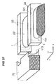
- FIG. 3F shows a perspective view of an auxiliary component 72 and the insert member 22 of FIG. 3E , without that also the other components 21, 71 of the FIG. 3E are shown. It is also the circumferential direction u shown, it being understood that the insert member 22 as well as the auxiliary member 72 extend (and of course the support member, not shown) in the circumferential direction, said extension over part of the circumference of the main flow path boundary or over the entire Scope of the main flow path boundary can be made, and wherein the structures for forming a secondary flow channel 1 repeat along the circumference.
- the recesses 221 can be seen in the insert member 22, which form part of the surfaces of the secondary flow channel 1. Also, the surfaces are consistently concave curvature 113 and continuous convex curvature 114 on the auxiliary member 72 and the insert member 22 can be seen.
- the invention is not limited in its embodiment to the embodiments shown above, which are to be understood only as examples.
- shape and configuration of the secondary flow channels and of the components providing them can be realized in a different manner than illustrated.
Landscapes
- Engineering & Computer Science (AREA)
- Mechanical Engineering (AREA)
- General Engineering & Computer Science (AREA)
- Structures Of Non-Positive Displacement Pumps (AREA)
Applications Claiming Priority (1)
| Application Number | Priority Date | Filing Date | Title |
|---|---|---|---|
| DE102013210168.6A DE102013210168A1 (de) | 2013-05-31 | 2013-05-31 | Strukturbaugruppe für eine Strömungsmaschine |
Publications (1)
| Publication Number | Publication Date |
|---|---|
| EP2808557A1 true EP2808557A1 (fr) | 2014-12-03 |
Family
ID=50842101
Family Applications (1)
| Application Number | Title | Priority Date | Filing Date |
|---|---|---|---|
| EP14170060.9A Withdrawn EP2808557A1 (fr) | 2013-05-31 | 2014-05-27 | Ensemble structurel pour une turbomachine |
Country Status (3)
| Country | Link |
|---|---|
| US (1) | US9664204B2 (fr) |
| EP (1) | EP2808557A1 (fr) |
| DE (1) | DE102013210168A1 (fr) |
Families Citing this family (5)
| Publication number | Priority date | Publication date | Assignee | Title |
|---|---|---|---|---|
| EP2818724B1 (fr) * | 2013-06-27 | 2020-09-23 | MTU Aero Engines GmbH | Turbomachine et procédé |
| US10876549B2 (en) | 2019-04-05 | 2020-12-29 | Pratt & Whitney Canada Corp. | Tandem stators with flow recirculation conduit |
| US11702945B2 (en) | 2021-12-22 | 2023-07-18 | Rolls-Royce North American Technologies Inc. | Turbine engine fan case with tip injection air recirculation passage |
| US11946379B2 (en) | 2021-12-22 | 2024-04-02 | Rolls-Royce North American Technologies Inc. | Turbine engine fan case with manifolded tip injection air recirculation passages |
| US11732612B2 (en) | 2021-12-22 | 2023-08-22 | Rolls-Royce North American Technologies Inc. | Turbine engine fan track liner with tip injection air recirculation passage |
Citations (12)
| Publication number | Priority date | Publication date | Assignee | Title |
|---|---|---|---|---|
| EP0497574A1 (fr) | 1991-01-30 | 1992-08-05 | United Technologies Corporation | Virole avec canaux de récirculation pour soufflante |
| EP0751280A1 (fr) * | 1995-05-31 | 1997-01-02 | United Technologies Corporation | Paroi avec plenum pour l'alignement de l'écoulement dans les aubes de compresseur |
| EP0754864A1 (fr) | 1995-07-18 | 1997-01-22 | Ebara Corporation | Turbomachine |
| DE19647605A1 (de) * | 1996-11-18 | 1998-05-28 | Daimler Benz Ag | Abgas-Turbolader für Brennkraftmaschinen |
| DE10105456A1 (de) * | 2001-02-07 | 2002-08-08 | Daimler Chrysler Ag | Verdichter, insbesondere für eine Brennkraftmaschine |
| DE10135003C1 (de) | 2001-07-18 | 2002-10-02 | Mtu Aero Engines Gmbh | Verdichtergehäusestruktur |
| US6585479B2 (en) | 2001-08-14 | 2003-07-01 | United Technologies Corporation | Casing treatment for compressors |
| DE10330084A1 (de) | 2002-08-23 | 2004-03-04 | Mtu Aero Engines Gmbh | Rezirkulationsstruktur für Turboverdichter |
| US20050226717A1 (en) | 2004-04-13 | 2005-10-13 | Rolls-Royce Plc | Flow control arrangement |
| EP1659293A2 (fr) * | 2004-11-17 | 2006-05-24 | Rolls-Royce Deutschland Ltd & Co KG | Turbomachine |
| EP2108784A2 (fr) * | 2008-04-08 | 2009-10-14 | Rolls-Royce Deutschland Ltd & Co KG | Turbomachine dotée d'un composant d'injecteur de fluide |
| DE102008037154A1 (de) | 2008-08-08 | 2010-02-11 | Rolls-Royce Deutschland Ltd & Co Kg | Strömungsarbeitsmaschine |
Family Cites Families (5)
| Publication number | Priority date | Publication date | Assignee | Title |
|---|---|---|---|---|
| FR1155958A (fr) * | 1956-03-28 | 1958-05-12 | Perfectionnements aux turbines à fluide compressible | |
| US5431533A (en) * | 1993-10-15 | 1995-07-11 | United Technologies Corporation | Active vaned passage casing treatment |
| US5562404A (en) * | 1994-12-23 | 1996-10-08 | United Technologies Corporation | Vaned passage hub treatment for cantilever stator vanes |
| US5474417A (en) * | 1994-12-29 | 1995-12-12 | United Technologies Corporation | Cast casing treatment for compressor blades |
| FR2949518B1 (fr) * | 2009-08-31 | 2011-10-21 | Snecma | Compresseur de turbomachine ayant des injecteurs d'air |
-
2013
- 2013-05-31 DE DE102013210168.6A patent/DE102013210168A1/de not_active Withdrawn
-
2014
- 2014-05-27 EP EP14170060.9A patent/EP2808557A1/fr not_active Withdrawn
- 2014-05-28 US US14/289,291 patent/US9664204B2/en not_active Expired - Fee Related
Patent Citations (13)
| Publication number | Priority date | Publication date | Assignee | Title |
|---|---|---|---|---|
| EP0497574A1 (fr) | 1991-01-30 | 1992-08-05 | United Technologies Corporation | Virole avec canaux de récirculation pour soufflante |
| EP0751280A1 (fr) * | 1995-05-31 | 1997-01-02 | United Technologies Corporation | Paroi avec plenum pour l'alignement de l'écoulement dans les aubes de compresseur |
| EP0754864A1 (fr) | 1995-07-18 | 1997-01-22 | Ebara Corporation | Turbomachine |
| DE19647605A1 (de) * | 1996-11-18 | 1998-05-28 | Daimler Benz Ag | Abgas-Turbolader für Brennkraftmaschinen |
| DE10105456A1 (de) * | 2001-02-07 | 2002-08-08 | Daimler Chrysler Ag | Verdichter, insbesondere für eine Brennkraftmaschine |
| DE10135003C1 (de) | 2001-07-18 | 2002-10-02 | Mtu Aero Engines Gmbh | Verdichtergehäusestruktur |
| US6585479B2 (en) | 2001-08-14 | 2003-07-01 | United Technologies Corporation | Casing treatment for compressors |
| DE10330084A1 (de) | 2002-08-23 | 2004-03-04 | Mtu Aero Engines Gmbh | Rezirkulationsstruktur für Turboverdichter |
| US20050226717A1 (en) | 2004-04-13 | 2005-10-13 | Rolls-Royce Plc | Flow control arrangement |
| EP1659293A2 (fr) * | 2004-11-17 | 2006-05-24 | Rolls-Royce Deutschland Ltd & Co KG | Turbomachine |
| EP2108784A2 (fr) * | 2008-04-08 | 2009-10-14 | Rolls-Royce Deutschland Ltd & Co KG | Turbomachine dotée d'un composant d'injecteur de fluide |
| US8152445B2 (en) | 2008-04-08 | 2012-04-10 | Rolls-Royce Deutschland Ltd & Co Kg | Fluid flow machine with fluid injector assembly |
| DE102008037154A1 (de) | 2008-08-08 | 2010-02-11 | Rolls-Royce Deutschland Ltd & Co Kg | Strömungsarbeitsmaschine |
Also Published As
| Publication number | Publication date |
|---|---|
| DE102013210168A1 (de) | 2014-12-04 |
| US20140356144A1 (en) | 2014-12-04 |
| US9664204B2 (en) | 2017-05-30 |
Similar Documents
| Publication | Publication Date | Title |
|---|---|---|
| EP2808559B1 (fr) | Ensemble structurel pour une turbomachine | |
| EP2025945B1 (fr) | Machine de traitement des écoulements dotée d'un creux de paroi de canal de ceinture | |
| EP2808556B1 (fr) | Ensemble structurel pour une turbomachine | |
| EP2108784B1 (fr) | Turbomachine dotée d'un composant d'injecteur de fluide | |
| EP1659293B1 (fr) | Turbomachine | |
| EP1382855B1 (fr) | Turbomachine avec système de recirculation de fluide intégré | |
| EP2110559B1 (fr) | Turbomachine avec réinjection de fluide pour influencer la couche limite | |
| EP1609999B1 (fr) | Turbo machine | |
| DE3700668C2 (de) | Übergangskanaldichtvorrichtung | |
| EP2132414B1 (fr) | Agencement en feuillure | |
| DE2915626A1 (de) | Kuehlluftleitung fuer ein gasturbinentriebwerk | |
| DE102008011644A1 (de) | Gehäusestrukturierung für Axialverdichter im Nabenbereich | |
| EP2921716B1 (fr) | Groupe de série d'aubes | |
| DE102008052401A1 (de) | Strömungsarbeitsmaschine mit Laufspalteinzug | |
| EP3064706A1 (fr) | Rangée d'aubes directrices pour une turbomachine traversée axialement | |
| EP2921714A1 (fr) | Groupe de série d'aubes | |
| EP2808557A1 (fr) | Ensemble structurel pour une turbomachine | |
| EP3236011B1 (fr) | Rotor comprenant un porte à faux sur les pales pour un élément de sécurité | |
| EP3078804A1 (fr) | Agencement virole pour une rangée d'aubes de rotor ou stator et turbine associée | |
| EP2846000B1 (fr) | Roue statorique d'une turbine à gaz | |
| DE3031553A1 (de) | Gasturbinenlaufrad. | |
| EP2808558B1 (fr) | Ensemble structurel pour une turbomachine | |
| DE102016124147B4 (de) | Innenkühlkonfigurationen in Turbinenrotorschaufeln | |
| EP2921715A1 (fr) | Groupe de série d'aubes | |
| EP2811117A2 (fr) | Anneau de renforcement pour une turbomachine |
Legal Events
| Date | Code | Title | Description |
|---|---|---|---|
| PUAI | Public reference made under article 153(3) epc to a published international application that has entered the european phase |
Free format text: ORIGINAL CODE: 0009012 |
|
| 17P | Request for examination filed |
Effective date: 20140527 |
|
| AK | Designated contracting states |
Kind code of ref document: A1 Designated state(s): AL AT BE BG CH CY CZ DE DK EE ES FI FR GB GR HR HU IE IS IT LI LT LU LV MC MK MT NL NO PL PT RO RS SE SI SK SM TR |
|
| AX | Request for extension of the european patent |
Extension state: BA ME |
|
| R17P | Request for examination filed (corrected) |
Effective date: 20150602 |
|
| RBV | Designated contracting states (corrected) |
Designated state(s): AL AT BE BG CH CY CZ DE DK EE ES FI FR GB GR HR HU IE IS IT LI LT LU LV MC MK MT NL NO PL PT RO RS SE SI SK SM TR |
|
| 17Q | First examination report despatched |
Effective date: 20170607 |
|
| STAA | Information on the status of an ep patent application or granted ep patent |
Free format text: STATUS: THE APPLICATION IS DEEMED TO BE WITHDRAWN |
|
| 18D | Application deemed to be withdrawn |
Effective date: 20200603 |