EP2110563A2 - Agencement de soupape doté d'un dispositif de fermeture central - Google Patents
Agencement de soupape doté d'un dispositif de fermeture central Download PDFInfo
- Publication number
- EP2110563A2 EP2110563A2 EP09002008A EP09002008A EP2110563A2 EP 2110563 A2 EP2110563 A2 EP 2110563A2 EP 09002008 A EP09002008 A EP 09002008A EP 09002008 A EP09002008 A EP 09002008A EP 2110563 A2 EP2110563 A2 EP 2110563A2
- Authority
- EP
- European Patent Office
- Prior art keywords
- valve
- shut
- consumer
- mounting base
- arrangement according
- Prior art date
- Legal status (The legal status is an assumption and is not a legal conclusion. Google has not performed a legal analysis and makes no representation as to the accuracy of the status listed.)
- Granted
Links
- 239000012530 fluid Substances 0.000 title claims description 26
- 230000000903 blocking effect Effects 0.000 claims abstract 3
- 238000004891 communication Methods 0.000 claims description 4
- 230000003993 interaction Effects 0.000 claims description 2
- 238000007789 sealing Methods 0.000 description 5
- 230000009471 action Effects 0.000 description 2
- 230000004913 activation Effects 0.000 description 2
- 230000007257 malfunction Effects 0.000 description 2
- 230000008901 benefit Effects 0.000 description 1
- 238000006243 chemical reaction Methods 0.000 description 1
- 230000007547 defect Effects 0.000 description 1
- 230000001419 dependent effect Effects 0.000 description 1
- 238000011161 development Methods 0.000 description 1
- 230000018109 developmental process Effects 0.000 description 1
- 238000010348 incorporation Methods 0.000 description 1
- 230000005405 multipole Effects 0.000 description 1
- 238000010079 rubber tapping Methods 0.000 description 1
- 230000003584 silencer Effects 0.000 description 1
- 239000013589 supplement Substances 0.000 description 1
- 230000002123 temporal effect Effects 0.000 description 1
Images



Classifications
-
- F—MECHANICAL ENGINEERING; LIGHTING; HEATING; WEAPONS; BLASTING
- F15—FLUID-PRESSURE ACTUATORS; HYDRAULICS OR PNEUMATICS IN GENERAL
- F15B—SYSTEMS ACTING BY MEANS OF FLUIDS IN GENERAL; FLUID-PRESSURE ACTUATORS, e.g. SERVOMOTORS; DETAILS OF FLUID-PRESSURE SYSTEMS, NOT OTHERWISE PROVIDED FOR
- F15B20/00—Safety arrangements for fluid actuator systems; Applications of safety devices in fluid actuator systems; Emergency measures for fluid actuator systems
-
- F—MECHANICAL ENGINEERING; LIGHTING; HEATING; WEAPONS; BLASTING
- F15—FLUID-PRESSURE ACTUATORS; HYDRAULICS OR PNEUMATICS IN GENERAL
- F15B—SYSTEMS ACTING BY MEANS OF FLUIDS IN GENERAL; FLUID-PRESSURE ACTUATORS, e.g. SERVOMOTORS; DETAILS OF FLUID-PRESSURE SYSTEMS, NOT OTHERWISE PROVIDED FOR
- F15B13/00—Details of servomotor systems ; Valves for servomotor systems
- F15B13/02—Fluid distribution or supply devices characterised by their adaptation to the control of servomotors
- F15B13/06—Fluid distribution or supply devices characterised by their adaptation to the control of servomotors for use with two or more servomotors
- F15B13/08—Assemblies of units, each for the control of a single servomotor only
- F15B13/0803—Modular units
- F15B13/0807—Manifolds
- F15B13/0814—Monoblock manifolds
-
- F—MECHANICAL ENGINEERING; LIGHTING; HEATING; WEAPONS; BLASTING
- F15—FLUID-PRESSURE ACTUATORS; HYDRAULICS OR PNEUMATICS IN GENERAL
- F15B—SYSTEMS ACTING BY MEANS OF FLUIDS IN GENERAL; FLUID-PRESSURE ACTUATORS, e.g. SERVOMOTORS; DETAILS OF FLUID-PRESSURE SYSTEMS, NOT OTHERWISE PROVIDED FOR
- F15B13/00—Details of servomotor systems ; Valves for servomotor systems
- F15B13/02—Fluid distribution or supply devices characterised by their adaptation to the control of servomotors
- F15B13/06—Fluid distribution or supply devices characterised by their adaptation to the control of servomotors for use with two or more servomotors
- F15B13/08—Assemblies of units, each for the control of a single servomotor only
- F15B13/0803—Modular units
- F15B13/0832—Modular valves
- F15B13/0839—Stacked plate type valves
-
- F—MECHANICAL ENGINEERING; LIGHTING; HEATING; WEAPONS; BLASTING
- F15—FLUID-PRESSURE ACTUATORS; HYDRAULICS OR PNEUMATICS IN GENERAL
- F15B—SYSTEMS ACTING BY MEANS OF FLUIDS IN GENERAL; FLUID-PRESSURE ACTUATORS, e.g. SERVOMOTORS; DETAILS OF FLUID-PRESSURE SYSTEMS, NOT OTHERWISE PROVIDED FOR
- F15B13/00—Details of servomotor systems ; Valves for servomotor systems
- F15B13/02—Fluid distribution or supply devices characterised by their adaptation to the control of servomotors
- F15B13/06—Fluid distribution or supply devices characterised by their adaptation to the control of servomotors for use with two or more servomotors
- F15B13/08—Assemblies of units, each for the control of a single servomotor only
- F15B13/0803—Modular units
- F15B13/0871—Channels for fluid
-
- F—MECHANICAL ENGINEERING; LIGHTING; HEATING; WEAPONS; BLASTING
- F16—ENGINEERING ELEMENTS AND UNITS; GENERAL MEASURES FOR PRODUCING AND MAINTAINING EFFECTIVE FUNCTIONING OF MACHINES OR INSTALLATIONS; THERMAL INSULATION IN GENERAL
- F16K—VALVES; TAPS; COCKS; ACTUATING-FLOATS; DEVICES FOR VENTING OR AERATING
- F16K27/00—Construction of housing; Use of materials therefor
- F16K27/003—Housing formed from a plurality of the same valve elements
-
- F—MECHANICAL ENGINEERING; LIGHTING; HEATING; WEAPONS; BLASTING
- F16—ENGINEERING ELEMENTS AND UNITS; GENERAL MEASURES FOR PRODUCING AND MAINTAINING EFFECTIVE FUNCTIONING OF MACHINES OR INSTALLATIONS; THERMAL INSULATION IN GENERAL
- F16K—VALVES; TAPS; COCKS; ACTUATING-FLOATS; DEVICES FOR VENTING OR AERATING
- F16K31/00—Actuating devices; Operating means; Releasing devices
- F16K31/44—Mechanical actuating means
- F16K31/52—Mechanical actuating means with crank, eccentric, or cam
- F16K31/524—Mechanical actuating means with crank, eccentric, or cam with a cam
- F16K31/52475—Mechanical actuating means with crank, eccentric, or cam with a cam comprising a sliding valve
- F16K31/52483—Mechanical actuating means with crank, eccentric, or cam with a cam comprising a sliding valve comprising a multiple-way sliding valve
Definitions
- the invention relates to a valve assembly having a mounting base, which is penetrated by a plurality of consumer connection channels, which on the one hand lead to a common mounting surface of the mounting base and on the other hand lead to off the mounting surface on the mounting base opening out, the connection of leading to consumers fluid lines connecting ports, wherein on the mounting surface equipped with a plurality of independently operable valve units valve block with a base in advance is mounted or mounted so that at the base opening out, controllable by the individual valve units consumer valve channels of the valve units are in fluid communication with the consumer connection channels of the mounting base ,
- One from the EP 0 968 372 B1 known valve assembly of this type includes a plate-shaped mounting base, which is interspersed inter alia by consumer connection channels, which are connectable via outgoing fluid lines with actuated consumers.
- the mounting base functions as a multi-port fluidic connection device for a valve block composed of a plurality of valve units, which is fixable as a unit interchangeable on the mounting base.
- the valve block be assembled and disassembled as needed, without having to solve individually leading to the consumer fluid lines.
- the mounting base may remain in place and only the valve block as a whole is removed.
- valve block Since, in particular in case of malfunction of the valve block before replacement no longer has the opportunity to drive the connected consumers to their normal position, the removal of the valve block may result in unwanted functions connected consumers, such as opening of fluid-operated grippers or an extension of working cylinders , This can lead to critical situations that require extensive prior security.
- the mounting base is equipped with a common shut-off and opening all consumer connection channels enabling Chiabsperr arthritis.
- the consumer connection channels of the mounting base can be shut off together before a removal or replacement of the valve block by a central actuation operation.
- the fluid contained in the fluid lines leading to the consumers remains trapped and the consumers, in particular actuators such as linear drives, rotary drives, grippers, etc., remain in their current position.
- Critical actions of the connected consumers are thus excluded, the valve block can be exchanged easily.
- the consumer connection channels are reopened by the central shut-off, so that the operation can be resumed without danger and often without reinitializing the entire system.
- the fluid supply of the valve block expediently also takes place, be it alone with the pressure medium to be supplied to the consumers to be controlled by the valve units or also, if appropriate, the pressure medium used for the electropneumatic pilot control of the valve units.
- the mounting base passing through at least one supply connection channel, together with the consumer connection channels is integrated into the function of Gottabsperr boots.
- the Gottabsperr worn is able to shut off all the mounting base passing through the connection channels, whether consumer connection channels or supply connection channels, in common and in particular at the same time or to be able to perform a quick and smooth valve block exchange.
- connection openings used for connecting fluid lines are expediently located on a common connection surface of the mounting base, this connection surface being expediently placed on a side of the mounting base opposite the mounting surface.
- the Facultyabsperr worn could be designed for example radio-controlled remote control.
- the function of the common shut-off and opening of existing in the mounting base connection channels expediently takes at least one switched on in the course of the connection channels, either in an open position or in a closed position switchable shut-off valve.
- all connection channels can be assigned together a single shut-off valve.
- a shut-off valve with a flat slide which traverses all connection channels and which has a number of openings corresponding to the number of connection channels which can be positioned either simultaneously in the course of the connection channels or outside the connection channels.
- shut-off valves despite the need for a larger number of shut-off valves, it is usually more convenient, because conventional valve components can be used, if the mounting base has a plurality of commonly operable shut-off valves, each used to control a single port or group of ports.
- each valve unit of the valve block is equipped with two consumer valve channels, each communicating with its own consumer connection channel of the mounting base. It is then expedient to assign in each case a separate shut-off valve to the resulting pairs of the respectively same valve unit of assigned consumer connection channels.
- the connecting ducts expediently extend transversely through a mounting plate of the mounting base which also has the mounting surface and also the connection surface.
- This mounting plate expediently consists of one piece, but in principle can also have a segmented structure. It is advantageous in any case if the mounting plate itself directly forms the common housing for all existing shut-off valves, in which the valve members of the shut-off valves are used without additional independent housing.
- valve members of all shut-off valves cooperate with a common adjusting member which is activated upon actuation of the Monabsperr issued.
- this may in particular be a rotatably mounted eccentric shaft, which acts on resiliently biased valve members of the shut-off valves.
- valve arrangement designated in its entirety by reference numeral 1 contains two main components in the form of an in particular substantially plate-like mounting base 2 and a valve block 3 detachably attachable to a preferably planar mounting surface 4 of the mounting base 2.
- valve block 3 a plurality of independently operable valve units 5 are summarized in the manner of a module.
- the entire valve block 3 is a self-supporting, uniformly manageable unit.
- valve units 5 are strung together within the valve block 3 in the axial direction of the longitudinal axis 6, wherein they are preferably attached directly to each other.
- the valve units 5 are designed in particular plate-shaped, with the longitudinal axis 6 at right angles extending plate planes.
- the row of valve units 5 is flanked on both end faces by a preferably plate-shaped end body 7.
- tie rods 8 pass through the closing body 7 and the valve units 5 in the axial direction of the longitudinal axis 6 and tighten these components tightly together.
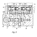
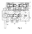
- the valve units 5 include, as in particular Figures 3 and 4
- the valve member 13 controls the fluid admission of two consumer valve channels 14, which open with first channel mouths 15 to a common outer surface of the valve housing 12.
- the first channel mouths 15 of all valve units 5 are located on identically oriented outer surfaces, which together, together with correspondingly oriented outer surfaces of the closing body 7, define a lying preferably in a plane base 16 of the valve block 3.
- the valve units 5 are of electrically actuated type. They receive their electrical actuation signals, for example via at least one electrical interface 17 arranged externally on the valve block 3. These can be directly electrically operable valves or, as in the exemplary embodiment, electro-hydraulically pilot operated valves. The instantaneous position of the valve member 13 is predetermined by fluidic output signals of at least one electrically actuable pilot valve 18 of the respective valve unit 5.
- valve housing 12 of the individual valve units 5 are interspersed in the transverse direction of individual openings 22, wherein the openings of immediately adjacent valve units 5 are aligned properly with each other and each to a complete assembly of valve units 5 passing through the continuous fluid channel 23, 24 supplement.
- One of these continuous fluid channels 23 is a feed channel through which all valve units 5 are supplied with the pressure medium to be controlled.
- One or two further continuous fluid channels 24 are designed as discharge channels and divert the pressure medium flowing back from the consumers to be controlled to the atmosphere or to a tank.
- valve members 13 can cause that at the consumer valve ports 14 from the feed channel 23 originating pressure medium is output to a connected consumer, or that is discharged from the connected load back pressure medium via the at least one discharge channel 24.
- the feed channel 23 is in communication with a first supply valve block channel 26 extending inside the valve block and opening out via a second channel mouth 25 to the base surface 16.
- a second supply valve block channel 27 also with a second channel mouth 25, which supplies the pilot valves 18 with pressure medium.
- discharge valve block channel 28 is connected to the at least one discharge channel 24 and also opens to the base 16 from.
- discharge channels 24 can also individually or through a common discharge opening to a remote from the base surface 16 outer surface of the valve block 3, as in FIG. 1 indicated by dash-dotted lines at 32.
- a silencer is expediently attached.
- the second channel openings 25 of the two supply valve block channels 26, 27 are arranged together on one of the two closing bodies 7.
- the discharge valve block channel 28 opens by way of example at the other end body 7.
- the mounting base 2 designed as an independent structural unit with respect to the valve block 3 contains a preferably integrally formed mounting plate 33, whose one large-area outer surface forms the above-mentioned mounting surface 4.
- the valve block 3 can be recognized with its base 16 ahead of the mounting surface 4 and in this attached state be releasably connected to the mounting base 2.
- fastening screws which pass through the valve block 3 through fastening openings 34 at right angles to the base surface 16 and into aligned threaded holes 35 of the mounting plate 33 are screwed.
- fastening screws which pass through the valve block 3 through fastening openings 34 at right angles to the base surface 16 and into aligned threaded holes 35 of the mounting plate 33 are screwed.
- the valve block 3 with the mounting base 2 can be firmly clamped.
- the mounting plate 33 is traversed transversely to its plane of the plate of a number of the first channel openings 15 corresponding number of consumer connection channels 36.
- the consumer connection channels 36 terminate in a distribution pattern corresponding to the distribution pattern of the first channel openings 15 distribution pattern to the mounting surface 4, so that when the valve block 3 is ever a consumer valve channel 14 communicates with a consumer connection channel 36.
- a sealing element 39 is interposed for sealing in each case.
- Each consumer connection channel 36 opens via a connection opening 37 to a connection surface 38 of the mounting plate 33, which is expediently located on the base surface 16 opposite side of the plate and opposite to the mounting surface 4 is oriented.
- connection openings 43 which open out like the consumer connection channels 36 to the connection surface 38.
- the supply valve block channels 26, 27 communicate with each one of the supply connection channels 42. Again, suitable sealing elements are suitably interposed.
- connection openings 37, 43 are equipped with connection means such as threads, plug connection devices, etc., which allow the particular detachable connection of fluid lines 45, which lead in the case of the consumer connection channels 36 to the consumers to be driven and in the case of the supply connection channels 42 to the pressure source P are connected.
- connection means such as threads, plug connection devices, etc.
- the mounting base 2 is equipped with a Monabsperr worn 46, the common shut-off and opening all consumer connection channels 36 and supply connection channels 42 allows.
- all consumer connection channels 36 and all supply connection channels 42 can be shut off by a central handling, so that on the one hand in the connected to the consumer connection channels 36 fluid lines 45 existing pressure medium is locked - with the result in that the connected consumers remain in their current operating state - and, on the other hand, leakage of the supply connection channels 42 to the pressurized medium to the atmosphere is prevented.
- connection channels thus only the consumer connection channels 36 and the supply connection channels 42 are meant.
- the Monabsperr worn 46 includes a plurality of shut-off valves 47, which are each turned on in the course of one or more of the connection channels 36, 42 and which are two-position valves, which can optionally take a fluid passage enabling the open position or a fluid passage preventing the closed position.
- Each of the multiple shut-off valves 47 thus simultaneously controls a plurality of connection channels 36, 42, but preferably only identical connection channels are combined in these channel groups.
- each valve unit 5 is assigned its own shut-off valve 47, which controls the consumer connection channels 36 connected to this valve unit 5.
- each shut-off valve 47 controls those two consumer ports 36 communicating with one and the same valve unit 5 when the valve block 3 is mounted.
- the two supply connection channels 42 are in turn assigned their own shut-off valve 47.
- the distribution grid here corresponds to that of the valve units 5.
- the shut-off valves 47 in the axial direction of the longitudinal axis 6 parallel to the longitudinal axis 48 of the mounting base 2 are arranged successively, with its longitudinal axis perpendicular to the Longitudinal axis 48 extends, so that there is a longitudinal side by side, as in the valve units 5.
- the shut-off valves 47 can be accommodated in a confined space side by side in the mounting base 2.
- All shut-off valves 47 may be actuated by operation of a common one located on board the mounting base Central actuator 52 are actuated together, so that they are switched in particular simultaneously from the currently occupied position to the other position, so for example from the open position to the closed position.
- a particularly compact design results in the embodiment in that for the shut-off valves 47 no separate valve housing are present, but that directly the mounting plate 33 takes over the housing function for the shut-off valves.
- the mounting plate 33 is provided with a series of successively arranged in the axial direction of the longitudinal axis 48, in particular in the same plane and perpendicular to this longitudinal axis 48 aligned recesses, the valve chambers 53 form, which turned on in the course of the controlled connection channels 36, 42 are and each receive a double arrow 54 movable valve member 55.
- the valve member 55 is in particular designed as a valve slide, which has length portions of different diameters, which can cooperate with housing-fixed, in particular of sealing rings formed sealing surfaces 56.
- the function is that of conventional shut-off valves, so that further details regarding the operation at this point unnecessary.
- the valve members 55 are provided on the facing each other in the same axial direction end face with an actuating portion 56 - for example, a projection - and are constantly under the force of a particular rear acting on them, housed inside the mounting plate 33 return spring 57, through which they their actuating portion 56 are pressed against the outer periphery of an eccentric shaft 58.
- the eccentric shaft 58 extends parallel to the longitudinal axis 48 frontally in front of the actuating portions 56 all valve members 55 past and is rotatable about its central center axis 62. It may be housed directly in the mounting plate 33 or preferably in an independent housing body 63 which is laterally attached to the mounting plate 33 and in which the valve members 55 protrude with its actuating portion 56.
- the valve members 55 are constantly pressed against the eccentric outer periphery of the eccentric shaft 58.
- the above-mentioned central actuator 52 is formed in the embodiment as arranged on the eccentric shaft 58 outside of the housing body 63. Lever. He settles between one FIGS. 1 . 2 . 3 and 5 apparent first lever position and one off FIGS. 4 and 6 pivoting apparent second lever position, then at the same time the eccentric shaft 58 is rotated. The latter causes the valve members 55, which are supported on the eccentric shaft 58, depending on the direction of rotation, either against the spring force of the restoring spring 57 from the in Figures 3 and 5 apparent closing position in the in FIGS.
- the first lever position defines the closed position of the shut-off valves 47 and thus the shut-off position of the central shut-off device 46.
- the second lever position defines the open position of the shut-off valves 47 and consequently also the open position of the central shut-off device 46.
- the central actuator 52 works purely mechanically with the valve members 55 together. It is operated manually without external energy. Deviating from this, however, a design would be conceivable in which the central operating member 52 according to the dot-dash line Presentation in FIG. 2 is merely a manually operable trigger, such as a switch of an electrical actuator 64, which causes electrical signals upon activation, which then trigger an electrical or Elektrofluidisches switching the shut-off valves 47.
- each shut-off valve 47 can also be assigned its own adjusting member, for example an electromagnet or an electro-fluidic converter, which are then actuated together upon activation of the central operating member 52.
- the supply connection channels 42 can also be equipped with a shut-off device independent of the central shut-off device 46, but incorporation into the central shut-off device 46 is particularly advantageous because in this case all the pressurized connection channels can be shut off together with one action or released again ,
Landscapes
- Engineering & Computer Science (AREA)
- General Engineering & Computer Science (AREA)
- Mechanical Engineering (AREA)
- Physics & Mathematics (AREA)
- Fluid Mechanics (AREA)
- Chemical & Material Sciences (AREA)
- Analytical Chemistry (AREA)
- Valve Housings (AREA)
- Multiple-Way Valves (AREA)
Applications Claiming Priority (1)
| Application Number | Priority Date | Filing Date | Title |
|---|---|---|---|
| DE200810018837 DE102008018837B3 (de) | 2008-04-15 | 2008-04-15 | Ventilanordnung mit Zentralabsperreinrichtung |
Publications (3)
| Publication Number | Publication Date |
|---|---|
| EP2110563A2 true EP2110563A2 (fr) | 2009-10-21 |
| EP2110563A3 EP2110563A3 (fr) | 2012-08-22 |
| EP2110563B1 EP2110563B1 (fr) | 2013-06-26 |
Family
ID=40418437
Family Applications (1)
| Application Number | Title | Priority Date | Filing Date |
|---|---|---|---|
| EP20090002008 Not-in-force EP2110563B1 (fr) | 2008-04-15 | 2009-02-13 | Agencement de soupape doté d'un dispositif de fermeture central |
Country Status (2)
| Country | Link |
|---|---|
| EP (1) | EP2110563B1 (fr) |
| DE (1) | DE102008018837B3 (fr) |
Cited By (1)
| Publication number | Priority date | Publication date | Assignee | Title |
|---|---|---|---|---|
| WO2020146149A1 (fr) * | 2019-01-08 | 2020-07-16 | Parker-Hannifin Corporation | Soupape de commande hydraulique ayant des orifices de travail en double et des fonctions de commande d'oscillation d'actionneur intégrées |
Families Citing this family (2)
| Publication number | Priority date | Publication date | Assignee | Title |
|---|---|---|---|---|
| DE102015001539B4 (de) * | 2015-02-06 | 2022-03-17 | Festo Se & Co. Kg | Ventilbatterie |
| DE102015001537B4 (de) * | 2015-02-06 | 2022-03-24 | Festo Se & Co. Kg | Ventilbatterie |
Citations (1)
| Publication number | Priority date | Publication date | Assignee | Title |
|---|---|---|---|---|
| EP0968372B1 (fr) | 1997-03-18 | 2003-11-05 | Festo AG & Co | Arrangement de valves |
Family Cites Families (3)
| Publication number | Priority date | Publication date | Assignee | Title |
|---|---|---|---|---|
| JPH1038119A (ja) * | 1996-07-26 | 1998-02-13 | Ckd Corp | マニホールド |
| JP3280003B2 (ja) * | 1999-10-18 | 2002-04-30 | エスエムシー株式会社 | 電磁弁集合体用給排気装置 |
| DE102006010844A1 (de) * | 2006-03-09 | 2007-09-13 | Festo Ag & Co. | Ventilbatterie mit Sicherheitsventil |
-
2008
- 2008-04-15 DE DE200810018837 patent/DE102008018837B3/de not_active Expired - Fee Related
-
2009
- 2009-02-13 EP EP20090002008 patent/EP2110563B1/fr not_active Not-in-force
Patent Citations (1)
| Publication number | Priority date | Publication date | Assignee | Title |
|---|---|---|---|---|
| EP0968372B1 (fr) | 1997-03-18 | 2003-11-05 | Festo AG & Co | Arrangement de valves |
Cited By (3)
| Publication number | Priority date | Publication date | Assignee | Title |
|---|---|---|---|---|
| WO2020146149A1 (fr) * | 2019-01-08 | 2020-07-16 | Parker-Hannifin Corporation | Soupape de commande hydraulique ayant des orifices de travail en double et des fonctions de commande d'oscillation d'actionneur intégrées |
| US11448241B2 (en) | 2019-01-08 | 2022-09-20 | Parker-Hannifin Corporation | Hydraulic control valve with duplicate workports and integrated actuator oscillation control features |
| US11644050B2 (en) | 2019-01-08 | 2023-05-09 | Parker-Hannifin Corporation | Hydraulic control valve with duplicate workports and integrated actuator oscillation control features |
Also Published As
| Publication number | Publication date |
|---|---|
| EP2110563B1 (fr) | 2013-06-26 |
| DE102008018837B3 (de) | 2009-04-09 |
| EP2110563A3 (fr) | 2012-08-22 |
Similar Documents
| Publication | Publication Date | Title |
|---|---|---|
| EP0678676B1 (fr) | Bloc-valve | |
| EP2638297B1 (fr) | Entraînement hydraulique ou pneumatique pour l'actionnement d'un appareil de robinetterie comportant une soupape de réglage ou de commande | |
| DE19711227C2 (de) | Ventilanordnung | |
| DE102013016652B4 (de) | Ventilbatterie mit Sicherheitsventil | |
| DE102018204361B3 (de) | Mehrwegeventil und Verfahren zu seinem Betreiben | |
| DE69822963T2 (de) | Verbindungseinrichtung für ein Wegeventil | |
| EP3695125A1 (fr) | Système de soupapes et procédé de commande | |
| EP1041325B1 (fr) | Assemblage de soupapes | |
| EP2110563B1 (fr) | Agencement de soupape doté d'un dispositif de fermeture central | |
| EP1818547B1 (fr) | Dispositif d'entretien d'air comprimé | |
| EP1991791B1 (fr) | Batterie de distributeurs à distributeur de sécurité | |
| EP1780421B1 (fr) | Batterie de soupapes | |
| DE102021213469B3 (de) | Sicherheitsventileinrichtung | |
| EP2140183B1 (fr) | Batterie de soupapes piezoelectrique | |
| DE102018200680B4 (de) | Drucküberwachungsvorrichtung und damit ausgestattete Ventilanordnung | |
| DE102012021462A1 (de) | Ventileinheit | |
| EP2674652B1 (fr) | Agencement de soupape avec vannes à manchon | |
| DE3420631C2 (fr) | ||
| EP2217812B1 (fr) | Ensemble de soupapes et systeme d'armoire de distribution equipe de cet ensemble | |
| DE10213397B4 (de) | Ventilanordnung | |
| EP2770216B1 (fr) | Agencement de vannes | |
| DE2929578C2 (fr) | ||
| EP2789512B1 (fr) | Dispositif de préparation d'air comprimé pour un véhicule utilitaire | |
| DE3812116A1 (de) | Elektrohydraulisches wegeventil | |
| DE102011013187B4 (de) | Abluftnutzschaltung |
Legal Events
| Date | Code | Title | Description |
|---|---|---|---|
| PUAI | Public reference made under article 153(3) epc to a published international application that has entered the european phase |
Free format text: ORIGINAL CODE: 0009012 |
|
| AK | Designated contracting states |
Kind code of ref document: A2 Designated state(s): AT BE BG CH CY CZ DE DK EE ES FI FR GB GR HR HU IE IS IT LI LT LU LV MC MK MT NL NO PL PT RO SE SI SK TR |
|
| AX | Request for extension of the european patent |
Extension state: AL BA RS |
|
| PUAL | Search report despatched |
Free format text: ORIGINAL CODE: 0009013 |
|
| AK | Designated contracting states |
Kind code of ref document: A3 Designated state(s): AT BE BG CH CY CZ DE DK EE ES FI FR GB GR HR HU IE IS IT LI LT LU LV MC MK MT NL NO PL PT RO SE SI SK TR |
|
| AX | Request for extension of the european patent |
Extension state: AL BA RS |
|
| RIC1 | Information provided on ipc code assigned before grant |
Ipc: F16K 27/00 20060101ALI20120719BHEP Ipc: F15B 13/08 20060101AFI20120719BHEP Ipc: F16K 31/524 20060101ALI20120719BHEP Ipc: F15B 20/00 20060101ALI20120719BHEP |
|
| 17P | Request for examination filed |
Effective date: 20121024 |
|
| GRAP | Despatch of communication of intention to grant a patent |
Free format text: ORIGINAL CODE: EPIDOSNIGR1 |
|
| AKX | Designation fees paid |
Designated state(s): AT BE BG CH CY CZ DE DK EE ES FI FR GB GR HR HU IE IS IT LI LT LU LV MC MK MT NL NO PL PT RO SE SI SK TR |
|
| GRAS | Grant fee paid |
Free format text: ORIGINAL CODE: EPIDOSNIGR3 |
|
| GRAA | (expected) grant |
Free format text: ORIGINAL CODE: 0009210 |
|
| AK | Designated contracting states |
Kind code of ref document: B1 Designated state(s): AT BE BG CH CY CZ DE DK EE ES FI FR GB GR HR HU IE IS IT LI LT LU LV MC MK MT NL NO PL PT RO SE SI SK TR |
|
| REG | Reference to a national code |
Ref country code: GB Ref legal event code: FG4D Free format text: NOT ENGLISH |
|
| REG | Reference to a national code |
Ref country code: CH Ref legal event code: EP |
|
| REG | Reference to a national code |
Ref country code: AT Ref legal event code: REF Ref document number: 618814 Country of ref document: AT Kind code of ref document: T Effective date: 20130715 |
|
| REG | Reference to a national code |
Ref country code: IE Ref legal event code: FG4D Free format text: LANGUAGE OF EP DOCUMENT: GERMAN |
|
| REG | Reference to a national code |
Ref country code: DE Ref legal event code: R096 Ref document number: 502009007409 Country of ref document: DE Effective date: 20130822 |
|
| PG25 | Lapsed in a contracting state [announced via postgrant information from national office to epo] |
Ref country code: SI Free format text: LAPSE BECAUSE OF FAILURE TO SUBMIT A TRANSLATION OF THE DESCRIPTION OR TO PAY THE FEE WITHIN THE PRESCRIBED TIME-LIMIT Effective date: 20130626 Ref country code: FI Free format text: LAPSE BECAUSE OF FAILURE TO SUBMIT A TRANSLATION OF THE DESCRIPTION OR TO PAY THE FEE WITHIN THE PRESCRIBED TIME-LIMIT Effective date: 20130626 Ref country code: SE Free format text: LAPSE BECAUSE OF FAILURE TO SUBMIT A TRANSLATION OF THE DESCRIPTION OR TO PAY THE FEE WITHIN THE PRESCRIBED TIME-LIMIT Effective date: 20130626 Ref country code: GR Free format text: LAPSE BECAUSE OF FAILURE TO SUBMIT A TRANSLATION OF THE DESCRIPTION OR TO PAY THE FEE WITHIN THE PRESCRIBED TIME-LIMIT Effective date: 20130927 Ref country code: LT Free format text: LAPSE BECAUSE OF FAILURE TO SUBMIT A TRANSLATION OF THE DESCRIPTION OR TO PAY THE FEE WITHIN THE PRESCRIBED TIME-LIMIT Effective date: 20130626 Ref country code: NO Free format text: LAPSE BECAUSE OF FAILURE TO SUBMIT A TRANSLATION OF THE DESCRIPTION OR TO PAY THE FEE WITHIN THE PRESCRIBED TIME-LIMIT Effective date: 20130926 |
|
| REG | Reference to a national code |
Ref country code: LT Ref legal event code: MG4D |
|
| PG25 | Lapsed in a contracting state [announced via postgrant information from national office to epo] |
Ref country code: HR Free format text: LAPSE BECAUSE OF FAILURE TO SUBMIT A TRANSLATION OF THE DESCRIPTION OR TO PAY THE FEE WITHIN THE PRESCRIBED TIME-LIMIT Effective date: 20130626 Ref country code: BG Free format text: LAPSE BECAUSE OF FAILURE TO SUBMIT A TRANSLATION OF THE DESCRIPTION OR TO PAY THE FEE WITHIN THE PRESCRIBED TIME-LIMIT Effective date: 20130926 |
|
| REG | Reference to a national code |
Ref country code: NL Ref legal event code: VDEP Effective date: 20130626 |
|
| PG25 | Lapsed in a contracting state [announced via postgrant information from national office to epo] |
Ref country code: LV Free format text: LAPSE BECAUSE OF FAILURE TO SUBMIT A TRANSLATION OF THE DESCRIPTION OR TO PAY THE FEE WITHIN THE PRESCRIBED TIME-LIMIT Effective date: 20130626 Ref country code: IT Free format text: LAPSE BECAUSE OF NON-PAYMENT OF DUE FEES Effective date: 20130213 |
|
| PG25 | Lapsed in a contracting state [announced via postgrant information from national office to epo] |
Ref country code: CY Free format text: LAPSE BECAUSE OF FAILURE TO SUBMIT A TRANSLATION OF THE DESCRIPTION OR TO PAY THE FEE WITHIN THE PRESCRIBED TIME-LIMIT Effective date: 20130807 Ref country code: SK Free format text: LAPSE BECAUSE OF FAILURE TO SUBMIT A TRANSLATION OF THE DESCRIPTION OR TO PAY THE FEE WITHIN THE PRESCRIBED TIME-LIMIT Effective date: 20130626 Ref country code: EE Free format text: LAPSE BECAUSE OF FAILURE TO SUBMIT A TRANSLATION OF THE DESCRIPTION OR TO PAY THE FEE WITHIN THE PRESCRIBED TIME-LIMIT Effective date: 20130626 Ref country code: IS Free format text: LAPSE BECAUSE OF FAILURE TO SUBMIT A TRANSLATION OF THE DESCRIPTION OR TO PAY THE FEE WITHIN THE PRESCRIBED TIME-LIMIT Effective date: 20131026 Ref country code: CZ Free format text: LAPSE BECAUSE OF FAILURE TO SUBMIT A TRANSLATION OF THE DESCRIPTION OR TO PAY THE FEE WITHIN THE PRESCRIBED TIME-LIMIT Effective date: 20130626 Ref country code: PT Free format text: LAPSE BECAUSE OF FAILURE TO SUBMIT A TRANSLATION OF THE DESCRIPTION OR TO PAY THE FEE WITHIN THE PRESCRIBED TIME-LIMIT Effective date: 20131028 |
|
| PG25 | Lapsed in a contracting state [announced via postgrant information from national office to epo] |
Ref country code: PL Free format text: LAPSE BECAUSE OF FAILURE TO SUBMIT A TRANSLATION OF THE DESCRIPTION OR TO PAY THE FEE WITHIN THE PRESCRIBED TIME-LIMIT Effective date: 20130626 Ref country code: NL Free format text: LAPSE BECAUSE OF FAILURE TO SUBMIT A TRANSLATION OF THE DESCRIPTION OR TO PAY THE FEE WITHIN THE PRESCRIBED TIME-LIMIT Effective date: 20130626 Ref country code: ES Free format text: LAPSE BECAUSE OF FAILURE TO SUBMIT A TRANSLATION OF THE DESCRIPTION OR TO PAY THE FEE WITHIN THE PRESCRIBED TIME-LIMIT Effective date: 20131007 Ref country code: RO Free format text: LAPSE BECAUSE OF FAILURE TO SUBMIT A TRANSLATION OF THE DESCRIPTION OR TO PAY THE FEE WITHIN THE PRESCRIBED TIME-LIMIT Effective date: 20130626 |
|
| PG25 | Lapsed in a contracting state [announced via postgrant information from national office to epo] |
Ref country code: CY Free format text: LAPSE BECAUSE OF FAILURE TO SUBMIT A TRANSLATION OF THE DESCRIPTION OR TO PAY THE FEE WITHIN THE PRESCRIBED TIME-LIMIT Effective date: 20130626 |
|
| PG25 | Lapsed in a contracting state [announced via postgrant information from national office to epo] |
Ref country code: DK Free format text: LAPSE BECAUSE OF FAILURE TO SUBMIT A TRANSLATION OF THE DESCRIPTION OR TO PAY THE FEE WITHIN THE PRESCRIBED TIME-LIMIT Effective date: 20130626 |
|
| PLBE | No opposition filed within time limit |
Free format text: ORIGINAL CODE: 0009261 |
|
| STAA | Information on the status of an ep patent application or granted ep patent |
Free format text: STATUS: NO OPPOSITION FILED WITHIN TIME LIMIT |
|
| 26N | No opposition filed |
Effective date: 20140327 |
|
| REG | Reference to a national code |
Ref country code: DE Ref legal event code: R097 Ref document number: 502009007409 Country of ref document: DE Effective date: 20140327 |
|
| BERE | Be: lapsed |
Owner name: FESTO A.G. & CO. KG Effective date: 20140228 |
|
| PG25 | Lapsed in a contracting state [announced via postgrant information from national office to epo] |
Ref country code: LU Free format text: LAPSE BECAUSE OF FAILURE TO SUBMIT A TRANSLATION OF THE DESCRIPTION OR TO PAY THE FEE WITHIN THE PRESCRIBED TIME-LIMIT Effective date: 20140213 Ref country code: MC Free format text: LAPSE BECAUSE OF FAILURE TO SUBMIT A TRANSLATION OF THE DESCRIPTION OR TO PAY THE FEE WITHIN THE PRESCRIBED TIME-LIMIT Effective date: 20130626 |
|
| REG | Reference to a national code |
Ref country code: CH Ref legal event code: PL |
|
| PG25 | Lapsed in a contracting state [announced via postgrant information from national office to epo] |
Ref country code: LI Free format text: LAPSE BECAUSE OF NON-PAYMENT OF DUE FEES Effective date: 20140228 Ref country code: CH Free format text: LAPSE BECAUSE OF NON-PAYMENT OF DUE FEES Effective date: 20140228 |
|
| REG | Reference to a national code |
Ref country code: IE Ref legal event code: MM4A |
|
| PG25 | Lapsed in a contracting state [announced via postgrant information from national office to epo] |
Ref country code: IE Free format text: LAPSE BECAUSE OF NON-PAYMENT OF DUE FEES Effective date: 20140213 Ref country code: BE Free format text: LAPSE BECAUSE OF NON-PAYMENT OF DUE FEES Effective date: 20140228 |
|
| REG | Reference to a national code |
Ref country code: AT Ref legal event code: MM01 Ref document number: 618814 Country of ref document: AT Kind code of ref document: T Effective date: 20140213 |
|
| PG25 | Lapsed in a contracting state [announced via postgrant information from national office to epo] |
Ref country code: AT Free format text: LAPSE BECAUSE OF NON-PAYMENT OF DUE FEES Effective date: 20140213 |
|
| REG | Reference to a national code |
Ref country code: FR Ref legal event code: PLFP Year of fee payment: 8 |
|
| PG25 | Lapsed in a contracting state [announced via postgrant information from national office to epo] |
Ref country code: MT Free format text: LAPSE BECAUSE OF FAILURE TO SUBMIT A TRANSLATION OF THE DESCRIPTION OR TO PAY THE FEE WITHIN THE PRESCRIBED TIME-LIMIT Effective date: 20130626 |
|
| PG25 | Lapsed in a contracting state [announced via postgrant information from national office to epo] |
Ref country code: TR Free format text: LAPSE BECAUSE OF FAILURE TO SUBMIT A TRANSLATION OF THE DESCRIPTION OR TO PAY THE FEE WITHIN THE PRESCRIBED TIME-LIMIT Effective date: 20130626 Ref country code: HU Free format text: LAPSE BECAUSE OF FAILURE TO SUBMIT A TRANSLATION OF THE DESCRIPTION OR TO PAY THE FEE WITHIN THE PRESCRIBED TIME-LIMIT; INVALID AB INITIO Effective date: 20090213 |
|
| REG | Reference to a national code |
Ref country code: FR Ref legal event code: PLFP Year of fee payment: 9 |
|
| PGFP | Annual fee paid to national office [announced via postgrant information from national office to epo] |
Ref country code: FR Payment date: 20170220 Year of fee payment: 9 |
|
| PGFP | Annual fee paid to national office [announced via postgrant information from national office to epo] |
Ref country code: GB Payment date: 20170126 Year of fee payment: 9 |
|
| PGFP | Annual fee paid to national office [announced via postgrant information from national office to epo] |
Ref country code: IT Payment date: 20170217 Year of fee payment: 9 |
|
| PG25 | Lapsed in a contracting state [announced via postgrant information from national office to epo] |
Ref country code: MK Free format text: LAPSE BECAUSE OF FAILURE TO SUBMIT A TRANSLATION OF THE DESCRIPTION OR TO PAY THE FEE WITHIN THE PRESCRIBED TIME-LIMIT Effective date: 20130626 |
|
| GBPC | Gb: european patent ceased through non-payment of renewal fee |
Effective date: 20180213 |
|
| REG | Reference to a national code |
Ref country code: FR Ref legal event code: ST Effective date: 20181031 |
|
| PG25 | Lapsed in a contracting state [announced via postgrant information from national office to epo] |
Ref country code: GB Free format text: LAPSE BECAUSE OF NON-PAYMENT OF DUE FEES Effective date: 20180213 Ref country code: FR Free format text: LAPSE BECAUSE OF NON-PAYMENT OF DUE FEES Effective date: 20180228 Ref country code: IT Free format text: LAPSE BECAUSE OF NON-PAYMENT OF DUE FEES Effective date: 20180213 |
|
| REG | Reference to a national code |
Ref country code: DE Ref legal event code: R082 Ref document number: 502009007409 Country of ref document: DE Representative=s name: PATENTANWAELTE MAGENBAUER & KOLLEGEN PARTNERSC, DE Ref country code: DE Ref legal event code: R081 Ref document number: 502009007409 Country of ref document: DE Owner name: FESTO SE & CO. KG, DE Free format text: FORMER OWNER: FESTO AG & CO. KG, 73734 ESSLINGEN, DE Ref country code: DE Ref legal event code: R081 Ref document number: 502009007409 Country of ref document: DE Owner name: FESTO AG & CO. KG, DE Free format text: FORMER OWNER: FESTO AG & CO. KG, 73734 ESSLINGEN, DE |
|
| PGFP | Annual fee paid to national office [announced via postgrant information from national office to epo] |
Ref country code: DE Payment date: 20191214 Year of fee payment: 12 |
|
| REG | Reference to a national code |
Ref country code: DE Ref legal event code: R119 Ref document number: 502009007409 Country of ref document: DE |
|
| PG25 | Lapsed in a contracting state [announced via postgrant information from national office to epo] |
Ref country code: DE Free format text: LAPSE BECAUSE OF NON-PAYMENT OF DUE FEES Effective date: 20210901 |