EP2217812B1 - Ensemble de soupapes et systeme d'armoire de distribution equipe de cet ensemble - Google Patents
Ensemble de soupapes et systeme d'armoire de distribution equipe de cet ensemble Download PDFInfo
- Publication number
- EP2217812B1 EP2217812B1 EP08748918A EP08748918A EP2217812B1 EP 2217812 B1 EP2217812 B1 EP 2217812B1 EP 08748918 A EP08748918 A EP 08748918A EP 08748918 A EP08748918 A EP 08748918A EP 2217812 B1 EP2217812 B1 EP 2217812B1
- Authority
- EP
- European Patent Office
- Prior art keywords
- valve
- valve assembly
- module
- assembly according
- seal
- Prior art date
- Legal status (The legal status is an assumption and is not a legal conclusion. Google has not performed a legal analysis and makes no representation as to the accuracy of the status listed.)
- Not-in-force
Links
- 239000012530 fluid Substances 0.000 claims description 42
- 238000009432 framing Methods 0.000 claims description 4
- 238000007789 sealing Methods 0.000 description 28
- 230000001419 dependent effect Effects 0.000 description 2
- 238000003780 insertion Methods 0.000 description 2
- 230000037431 insertion Effects 0.000 description 2
- 230000005405 multipole Effects 0.000 description 2
- 230000011218 segmentation Effects 0.000 description 2
- 238000000926 separation method Methods 0.000 description 2
- 230000000712 assembly Effects 0.000 description 1
- 238000000429 assembly Methods 0.000 description 1
- 230000004323 axial length Effects 0.000 description 1
- 238000006243 chemical reaction Methods 0.000 description 1
- 238000010276 construction Methods 0.000 description 1
- 239000000356 contaminant Substances 0.000 description 1
- 238000011161 development Methods 0.000 description 1
- 230000018109 developmental process Effects 0.000 description 1
- 230000003670 easy-to-clean Effects 0.000 description 1
- 238000007373 indentation Methods 0.000 description 1
- 238000002347 injection Methods 0.000 description 1
- 239000007924 injection Substances 0.000 description 1
- 238000009434 installation Methods 0.000 description 1
- 230000001681 protective effect Effects 0.000 description 1
- 238000004904 shortening Methods 0.000 description 1
- 230000007704 transition Effects 0.000 description 1
Images

Classifications
-
- F—MECHANICAL ENGINEERING; LIGHTING; HEATING; WEAPONS; BLASTING
- F15—FLUID-PRESSURE ACTUATORS; HYDRAULICS OR PNEUMATICS IN GENERAL
- F15B—SYSTEMS ACTING BY MEANS OF FLUIDS IN GENERAL; FLUID-PRESSURE ACTUATORS, e.g. SERVOMOTORS; DETAILS OF FLUID-PRESSURE SYSTEMS, NOT OTHERWISE PROVIDED FOR
- F15B13/00—Details of servomotor systems ; Valves for servomotor systems
- F15B13/02—Fluid distribution or supply devices characterised by their adaptation to the control of servomotors
- F15B13/06—Fluid distribution or supply devices characterised by their adaptation to the control of servomotors for use with two or more servomotors
- F15B13/08—Assemblies of units, each for the control of a single servomotor only
- F15B13/0803—Modular units
- F15B13/0807—Manifolds
- F15B13/0814—Monoblock manifolds
-
- F—MECHANICAL ENGINEERING; LIGHTING; HEATING; WEAPONS; BLASTING
- F15—FLUID-PRESSURE ACTUATORS; HYDRAULICS OR PNEUMATICS IN GENERAL
- F15B—SYSTEMS ACTING BY MEANS OF FLUIDS IN GENERAL; FLUID-PRESSURE ACTUATORS, e.g. SERVOMOTORS; DETAILS OF FLUID-PRESSURE SYSTEMS, NOT OTHERWISE PROVIDED FOR
- F15B13/00—Details of servomotor systems ; Valves for servomotor systems
- F15B13/02—Fluid distribution or supply devices characterised by their adaptation to the control of servomotors
- F15B13/06—Fluid distribution or supply devices characterised by their adaptation to the control of servomotors for use with two or more servomotors
- F15B13/08—Assemblies of units, each for the control of a single servomotor only
- F15B13/0803—Modular units
- F15B13/0807—Manifolds
- F15B13/0817—Multiblock manifolds
-
- F—MECHANICAL ENGINEERING; LIGHTING; HEATING; WEAPONS; BLASTING
- F15—FLUID-PRESSURE ACTUATORS; HYDRAULICS OR PNEUMATICS IN GENERAL
- F15B—SYSTEMS ACTING BY MEANS OF FLUIDS IN GENERAL; FLUID-PRESSURE ACTUATORS, e.g. SERVOMOTORS; DETAILS OF FLUID-PRESSURE SYSTEMS, NOT OTHERWISE PROVIDED FOR
- F15B13/00—Details of servomotor systems ; Valves for servomotor systems
- F15B13/02—Fluid distribution or supply devices characterised by their adaptation to the control of servomotors
- F15B13/06—Fluid distribution or supply devices characterised by their adaptation to the control of servomotors for use with two or more servomotors
- F15B13/08—Assemblies of units, each for the control of a single servomotor only
- F15B13/0803—Modular units
- F15B13/0828—Modular units characterised by sealing means of the modular units
-
- F—MECHANICAL ENGINEERING; LIGHTING; HEATING; WEAPONS; BLASTING
- F16—ENGINEERING ELEMENTS AND UNITS; GENERAL MEASURES FOR PRODUCING AND MAINTAINING EFFECTIVE FUNCTIONING OF MACHINES OR INSTALLATIONS; THERMAL INSULATION IN GENERAL
- F16K—VALVES; TAPS; COCKS; ACTUATING-FLOATS; DEVICES FOR VENTING OR AERATING
- F16K27/00—Construction of housing; Use of materials therefor
- F16K27/003—Housing formed from a plurality of the same valve elements
Definitions
- the invention relates to a valve assembly having a plurality of valve units serving to control fluid flows and having a module assembly composed of a plurality of modular bodies seated against each other in the direction of a major axis, which has a base composed of module body surfaces of the adjacent module bodies on the plurality of modules in the module assembly extending, provided for connecting fluid lines provided fluid channels.
- the invention further relates to a switchgear assembly which has a switchgear cabinet, on the wall of which a valve arrangement of the abovementioned type is mounted in such a way that its base surface faces a window-like opening of the wall unit.
- valve assembly of the aforementioned type is known, which consists of a composed of several juxtaposed modular bodies module assembly whose module body, apart from the closing bodies, are formed directly as valve units.
- the module assembly forms a valve assembly having a plurality of valve units for controlling fluid flows, disposed on an outside Base fluid channels open, which are controlled by the valve units.
- the modular design allows flexible assembly of the valve assembly and facilitates variations in their functionality.
- the applicant is also known a pressure-type documentary cabinet assembly having a cabinet in which a valve assembly of the aforementioned type is installed.
- the cabinet wall contains a window-like opening.
- a one-piece support plate is attached to the window-like opening, which is equipped with a serving for sealing with respect to the cabinet wall seal. In this way, the window-like opening is closed and prevents the ingress of contaminants into the interior of the cabinet.
- the modular valve assembly is mounted on the interior of the cabinet facing surface of the support plate.
- valve assembly independent module assembly which acts as a valve carrier and is releasably equipped with the valve assembly.
- a valve assembly is not suitable for lack of suitable sealing measures for mounting in a cabinet.
- valve assembly which has a one-piece support plate which is equipped with valve units. Each individual valve unit is surrounded by a protective cover which bears sealingly against the support plate in order to create a surface that is easy to clean. It is the object of the present invention to take measures with which a module assembly having a valve assembly can be easily and inexpensively install in a sealed manner in a control cabinet.
- the invention is further achieved by a switchgear assembly with a switch cabinet, the cabinet wall having a window-like opening, wherein on the inner surface of the cabinet wall at least one valve assembly of the aforementioned construction is mounted with its base ahead in such a way that the Dichtungsfactnut encloses the window-like opening and a in the Seal receiving groove arranged sealing member around the window-like aperture around sealingly against the inner surface of the cabinet wall.
- the seal receiving groove serving for receiving a sealing element sealing between the module bodies and the wall unit is formed directly in the base of the module assembly, so that it extends over a plurality of modular bodies arranged one behind the other and is composed of individual, mutually overlapping groove length sections. which are formed in the adjacent module body surfaces.
- the use of an additional one-piece support plate is unnecessary, which would have to be provided individually from case to case, depending on the size of the valve assembly. Since the groove length portions are formed in the module bodies themselves, the seal receiving groove in the direction of the major axis automatically lengthens or shortens with each insertion or removal of a module body.
- the Dichtungsingnut is suitable for receiving both frame-shaped self-contained sealing elements as well as strand-shaped, finite long sealing elements, which are cut individually with the desired length.
- the latter has the advantage that the cost of storage of sealing elements of different dimensions deleted.
- the module bodies can be formed at least partially directly by the valve units themselves.
- the module assembly in the form of a valve assembly having a plurality of valve units lined up in the direction of the main axis, which act as the module bodies.
- valve units are mounted on an example block- or plate-shaped, but segmented valve carrier, said segmented valve carrier forms the module assembly and its components obtained by the segmentation represent the module body.
- valve carrier is expediently traversed transversely to the direction of the main axis of at least some of the opening out on the base fluid channels, said fluid channels lead to a base surface opposite mounting surface of the valve carrier, where they communicate with the valve units mounted there.
- the valve carrier can form, for example, a type of fluidic multipole connection device, which merely realizes an extension of the valve channels of the valve units, it being possible to assemble and disassemble the valve units without having to remove fluid lines connected to the base area on the valve carrier.
- valve carrier as a fluid distributor component which is penetrated by one or more channels, via which at least some or preferably all valve units can be supplied together with pressure medium and, if required, also a common fluid discharge from the valve units is feasible.
- valve assembly may be provided at its the valve carrier facing pad in the same manner as the base of the valve carrier with a further Dichtungsfactnut.
- the gasket receiving groove may extend across all of the module body surfaces. However, if the module assembly contains, in particular at one or both of its end regions, also module bodies on whose module body surfaces no fluid channels Out, the Dichtungsingnut can also run so that it does not extend beyond these latter outer module body away.
- the seal receiving groove will extend over two outer module body surfaces as well as over one or more inner module body surfaces arranged between these two outer module body surfaces.
- the outer module body surfaces are expediently provided on the outer module bodies of the module assembly, but this is not mandatory.
- the groove-length sections of the seal-receiving groove running in the outer module body surfaces each have at least partially an opening in the. Have substantially U-shaped course and are placed so that the U-openings facing each other.
- the inner module body surfaces are each provided with two groove length sections spaced transversely to the main axis, which pass through the relevant inner module body surface in the axial direction of the main axis, so that they open out to the module body surfaces of the adjoining module body.
- an arrangement is possible in which the leg sections of the U-shaped groove longitudinal sections merge into a respective groove longitudinal section of the adjacent module body.
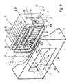
- the switchgear arrangement which is shown in the drawing and designated overall by reference numeral 1 comprises a switchgear cabinet 2 which is only partially illustrated and from which Fig. 2 to 4 only a section of its cabinet wall 3 can be seen.
- the cabinet wall 3 encloses an interior 4, in which a valve assembly 5, protected from external influences, is housed.
- the valve assembly 5 has a hereinafter referred to as base 6, expediently at least substantially flat outer surface. With this base 6 ahead of the valve assembly 5 can be attached to the inner surface 7 of the cabinet wall 3, to subsequently by fastening means. 8 releasably secured to the wall unit 3.
- the Fig. 3 shows a section through the releasably attached state.
- the cabinet 2 contains a not further apparent door through which the interior 4 is accessible for the required installation measures.
- channel openings 12 of running inside the valve assembly 5 fluid channels 13 there are numerous channel openings 12 of running inside the valve assembly 5 fluid channels 13.
- the channel openings 12 are equipped with not shown fastening means that allow a detachable connection of fluid lines 14, which lead to not further shown external devices.
- external devices are, for example, a pressure source which supplies the pressure medium required for the operation of the valve arrangement 5, or consumers, in particular fluid-operated drives, which can be acted upon by the valve arrangement 5 under pressure medium.
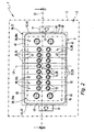
- the cabinet wall 3 has a window-like opening 15.
- the valve arrangement 5 is placed on the inner surface 7 such that the channel openings 12 come to rest within the window-like opening 15 and are thus accessible from outside the control cabinet 2.
- the base 6 has a greater extent than the cross section of the window-like opening 15, so that a frame-shaped edge portion 16 of the base 6 around the window-like aperture 15 around the inner surface 7 comes to rest and can be supported.
- a fastening means 8 for fixing the valve assembly 5 for example, screws are provided which pass through the cabinet wall 3 adjacent to the window-like opening 15 and are supported on retaining tabs 17 of the valve assembly 5.
- the Fixing means 8 are in particular designed so that the valve assembly 5 can be firmly clamped to the cabinet wall 3.
- the window-like opening 15 is completely covered by the valve assembly 5 mounted inside the cabinet wall 3.
- the valve assembly 5 includes an assembly, referred to as a module assembly 18, which is composed of a plurality of module bodies 22 which are juxtaposed in the direction of a major axis 23.
- a module assembly 18 is composed of a plurality of module bodies 22 which are juxtaposed in the direction of a major axis 23.
- tie rods which are passed through the module assembly 18 in the axial direction of the main axis 23 passing through fixing holes 24, the module body 22 are clamped together and held together to form the module assembly 18.
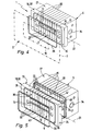
- the module assembly 18 is thus a uniformly manageable body, for example block-shaped as in the embodiment of Fig. 1 to 3 or also plate-shaped as in the embodiment of 4 and 5 ,
- Valve assembly 5 includes a plurality of valve units 25 for controlling fluid flow.
- Valve units 25 include internal valve means that are positionable in certain switch positions due to electrical actuation signals received to selectively shut off or release fluid paths.
- the valve means are designed, in particular, as pilot-controlled valve means and contain a main valve serving for the actual control of the fluid flows, which is actuated by fluidic signals which are supplied by at least one associated pilot control valve which can be actuated by electrical actuation signals.
- the valve means could also be designed for direct electrical control.
- valve units 25 are combined to form a modular valve assembly 27.
- they are lined up in the axial direction of the main axis 23 and summarized in the already described with reference to the module assembly 18 way to a self-supporting assembly in the form of the valve assembly 27.
- the valve assembly 27 has an at least substantially flat outer surface, which is referred to below as a connection surface 28 and open at the running in the interior of the valve assembly 27 valve channels 26.
- the above-mentioned valve means are capable of controlling the passage of fluid through at least some of the valve passages 26.
- valve assembly 27 which is identical to the module assembly 18, is mounted directly on the inner surface 7 of the cabinet wall 3.
- the module assembly 18 represents a valve carrier 32 which is segmented in the axial direction of the main axis 3 and has a mounting surface 33 on its side opposite the base surface 6, where the valve assembly 27 is detachably mounted.
- the Fig. 5 shows the separated state of the valve carrier 32 and the valve assembly 27th
- valve carrier 32 results from the realization in the form of the juxtaposed individual module body 22, which act here as valve carrier modules.
- valve carrier 32 In the embodiment of 4 and 5 enforce all of the opening to the base 6 fluid channels 13, the valve carrier 32 and open opposite to the channel openings 12 in a corresponding distribution of the mounting surface 33 from.
- the distribution of these channel openings corresponds to that of the existing at the terminal surface 28 of the valve assembly 27 channel mouths of the valve channels 26.
- the fluid channels 13 communicate in a dependent on the application case assignment with the valve channels 26 when the valve assembly 27 is mounted on the valve carrier 32.
- All or at least some of the fluid channels 13 are working channels to which consumers to be controlled via the fluid lines 14 can be connected. However, it is readily possible, one or more of the fluid channels 13 in such a way that via them an injection and / or discharge of the pressure medium takes place, with which the valve assembly 27 is operated. Thus, at least one fluid channel 13 could be designed as a feed channel and at least one further fluid channel 13 as a discharge channel. Several or all valve units 25 of the valve assembly 27 can be supplied or vented with pressure medium at the same time via these channels.
- valve assembly 27 it is also possible to handle the fluid supply of all the valve units 25 via a common feed channel 34 which does not lead to the base 6 or the Terminal surface 28 terminates, but at another outer surface of the valve assembly 27.
- a common all valve units 25 associated fluid discharge channel can be formed and arranged.
- valve carrier 32 only functions as a fluidic multipole connection device with respect to its fluidic function, in which each fluid channel 13 communicates with only one valve unit 25, it is of course also possible to have a design in which at least one fluid channel 13 is located in the module assembly 18 runs, that it is simultaneously connected to several of the attached valve units 25 in this way a common fluid supply or fluid removal can take place.
- a sealing element 36 is arranged in the Dichtungsingnut 35 .
- the sealing element 36 is likewise designed in the shape of a frame in accordance with the longitudinal course of the sealing receptacle 35 and can have a self-contained, endless shape, so that the channel openings 12 are enclosed by the mounted sealing element 36 in the same way as from the seal receiving groove 35.
- the sealing element 36 is, in particular, an independent component which is inserted into the seal receiving groove 35 after assembly of the module assembly 18. Its cross-sectional dimensions are matched to those of the Dichtungsingnut 35 that it protrudes slightly above the base 6, as long as the valve assembly 5 is not yet clamped to the cabinet wall 3. In this way, it is achieved that when permanently mounted on the cabinet wall 3 valve assembly 5, the sealing element 36 is pressed between the module assembly 18 and the cabinet wall 3 and thereby a reliable sealing contact is achieved.
- the sealing member 36 may also, as shown Fig.1 and 2 can be seen, a finally long before insertion into the Dichtungsfactnut 35, strand-shaped component, which is bendable and whose length substantially corresponds to that of the Dichtungsfactnut 35.
- the two end portions of the sealing element 36 lie in the inserted in the Dichtungsfactnut 35 state in the region of a separation point 37 directly opposite, where they can also touch.
- the end sections of the sealing element 36 are compressed and thus a reliable seal is achieved even in the region of the separation point 37.
- the realization of the sealing element 36 as an open strand element has the advantage that it can be cut to size from meter goods to any length and thus can be adapted effortlessly to the respective given length of the Dichtungsfactnut 35, so that a large storage effort is eliminated.
- the Dichtungsingnut 35 extends in the axial direction of the main axis 23 over a plurality of module body 22 away. In this case, a smaller than the existing number of module bodies 22 can be detected by the Dichtungsingnut 35, which is especially true if one or more of the outer axis in the axial direction of the main axis 23 module body 22 has no channel mouth 12 and the window-like aperture 15 thus has a cross section may be so small that one or more outer module body 22 does not protrude into the window-like opening 15.
- the base area 6 is composed of a plurality of area sections which are lined up in the axial direction of the main axis 23 and which are formed by the individual module bodies 22 and which are therefore referred to below as module body areas 38.
- the Dichtungsagenut 35 is composed of formed in the individual module body surfaces 38 groove-length sections 42, which merge into each other in the transition areas between adjacent module bodies 22.
- seal-receiving groove 35 It is also imaginable for the seal-receiving groove 35 to be created by dividing an originally frame-shaped closed groove into the individual groove-length sections 42 by segmenting the base surface 6.
- the module bodies 22 have an elongated shape at right angles to the main axis 23.
- the individual module body surfaces 38 are substantially strip-shaped, with a longitudinal axis 43 which runs parallel to the base surface 6 and at the same time perpendicular to the main axis 23.
- the Dichtungsagenut 35 has two opposite in the axial direction of the main axis 23 end portions 44 which are arranged in each case an outer module body surface 38, 38 a.
- the outer module body surfaces 38, 38a are located on the two module bodies 22 that terminate the module assembly 18 on both sides and beyond.
- the two end portions 44 forming groove length portions 42 are in particular U-shaped, with mutually facing U-openings.
- Each end portion 44 thereby has two leg sections 45 at right angles to the main axis 23, which are connected to one another by a transverse web of the U-forming connecting section 46 and whose free ends face the module body surface 38 of the respectively adjoining module body 22.
- inner module body surfaces 38b module body surfaces 38 of lying between the outer module bodies 22 inner module body 22 each have two groove longitudinal sections 42 which extend in the axial direction of the main axis 23 on the inner module body surface 38, 38b away. They are so perpendicular to the main axis 23 spaced from each other and arranged such that on the one hand, the groove length portions 42 adjacent inner module body surfaces 38, 38b into one another in alignment and on the other hand, the leg portions 45 with the groove length sections 42 of each subsequent inner module body surfaces 38, 38b are aligned.
- the Dichtungsingnut 35 has a rectangular course when looking at the base 6, in particular with rounded corners. Deviating from this, however, other longitudinal profiles are also possible, even with indentations and / or bulges and also within the individual module body surfaces 38 not rectilinear course.
- the outline enclosed by the seal receiving groove 35 in the area of the two outer module bodies 22 could have a greater width transversely to the main axis 23 than in the area of the module bodies 22 lying therebetween.
- the base surface 6 extends in a plane at least in the section 16 equipped with the seal-receiving groove 35, so that the seal-receiving groove 35 and the sealing element 36 to be placed therein can also extend in a single plane.
- the base 6 can also be uneven if necessary be formed and in particular have projections.
- 12 outstanding connection means are available from the channel openings, which allow a slight plug connection of the fluid lines 14.
- the previous description of the Dichtungsingnut 35 refers to the arrangement on the valve assembly 27.
- the description refers to the modular valve carrier 32.
- the valve carrier 32 to equip a valve assembly 27, wherein between these two components 32, 27 a seal comparable to that between the valve assembly 27 and the cabinet wall 3 in the embodiment of Fig. 1 to 3 takes place.
- a formed in the pad 28 further Dichtungsingnut 47 which framed all the channel mouths of the valve channels 26 and in which a further sealing element 48 is inserted, which is provided for sealing against the mounting surface 33.
- Structure and arrangement of the other Dichtungsingnut 47 and the other sealing element 48 correspond to those or those of the Dichtungsagenut 35 and the sealing element 36 in the embodiment of Fig. 1 to 3 ,
Landscapes
- Engineering & Computer Science (AREA)
- General Engineering & Computer Science (AREA)
- Mechanical Engineering (AREA)
- Physics & Mathematics (AREA)
- Fluid Mechanics (AREA)
- Valve Housings (AREA)
Claims (15)
- Ensemble de vanne comportant plusieurs unités de vanne (25) servant à la commande de courants fluidiques et un bloc modulaire (18) se composant de plusieurs corps modulaires (22) placés les uns contres les autres en direction d'un axe principal (23), le bloc modulaire présentant à l'extérieur une surface de base (6) se composant de surfaces (38) de corps modulaires (22) se trouvant les unes à côté des autres, surface de base sur laquelle débouchent plusieurs canaux fluidiques (13) s'étendant dans le bloc modulaire (18), et prévus pour le raccordement de conduites fluidiques (14), caractérisé en ce qu'une rainure de réception de garniture (35), servant à la réception d'un élément de garniture (36), et encadrant les embouchures de canaux qui s'y trouvent (12) des canaux fluidiques (13), est réalisée dans la surface de base (6), laquelle rainure s'étend sur plusieurs corps modulaires (22), sachant qu'elle se compose de sections longitudinales de rainure (42) passant les unes dans les autres, et réalisées dans des surfaces de corps modulaire (38) adjacentes.
- Ensemble de vanne selon la revendication 1, caractérisé en ce qu'il présente un élément de garniture (36) reçu par la rainure de réception de garniture (35).
- Ensemble de vanne selon la revendication 1 ou 2, caractérisé en ce qu'il présente un élément de garniture (36) autonome introduit dans la rainure de réception de garniture (35).
- Ensemble de vanne selon la revendication 3, caractérisé en ce que l'élément de garniture (36) est un élément de garniture (36) long en continu, en forme de barre, découpé à la longueur souhaitée.
- Ensemble de vanne selon l'une quelconque des revendications 1 à 4, caractérisé en ce que les corps modulaires (22) sont formés au moins en partie directement par les unités de vanne (25).
- Ensemble de vanne selon l'une quelconque des revendications 1 à 5 caractérisé en ce que le bloc modulaire (18) est formé par un bloc de vanne (27) présentant plusieurs unités de vanne (25) placées les unes sur les autres en direction de l'axe principal (23) et formant les corps modulaires (22).
- Ensemble de vanne selon l'une quelconque des revendications 1 à 4, caractérisé en ce que le bloc modulaire (18) forme un porte-vanne (32) segmenté en direction de l'axe principal (23) et présente, sur son côté opposé à la surface de base (6), une surface de montage (33), sur laquelle sont montées les unités de vanne (25).
- Ensemble de vanne selon la revendication 7, caractérisé en ce qu'au moins quelques-uns des canaux fluidiques (13) du bloc modulaire (18) débouchant vers la surface de base (6) débouchent aussi vers la surface de montage (33) et y communiquent avec des canaux de vanne (26) réalisés dans les unités de vanne (25) montées dessus.
- Ensemble de vanne selon la revendication 8, caractérisé en ce que les unités de vanne (25) sont réunies dans un bloc de vanne (27), dans lequel elles sont placées les unes sur les autres en direction de l'axe principal (23), sachant que le bloc de vanne (27) présente une surface de raccordement (28) se composant de surfaces extérieures des unités de vanne (25) se trouvant les unes à côté des autres, surface de raccordement sur laquelle débouchent plusieurs canaux de vanne (26) s'étendant dans les unités de vanne (25) et en liaison avec les canaux fluidiques (13) débouchant sur la surface de montage (33) du bloc modulaire (18).
- Ensemble de vanne selon la revendication 9, caractérisé en ce qu'une rainure de réception de garniture (47) supplémentaire encadrant les embouchures de canal qui s'y trouvent des canaux de vanne (26) est réalisée dans la surface de raccordement (28), laquelle rainure supplémentaire s'étend sur plusieurs unités de vanne (25), sachant qu'elle se compose de sections longitudinales de rainure (42) passant les unes dans les autres et réalisées dans des unités de vanne (25) adjacentes.
- Ensemble de vanne selon l'une quelconque des revendications 1 à 10, caractérisé en ce qu'il présente un élément de garniture autonome (48) introduit dans la rainure de réception de garniture (47) supplémentaire.
- Ensemble de vanne selon l'une quelconque des revendications 1 à 11, caractérisé en ce que la rainure de réception de garniture (35) s'étend sur toutes les surfaces de corps modulaire (38).
- Ensemble de vanne selon l'une quelconque des revendications 1 à 12, caractérisé en ce que la rainure de réception de garniture (35) s'étend dans une section de bord (16) encadrant les embouchures de canal (12) s'étendant dans un plan de la surface de base (6).
- Ensemble de vanne selon l'une quelconque des revendications 1 à 13, caractérisé en ce que la rainure de réception de garniture (35) s'étend dans deux surfaces de corps modulaire (38, 38a) extérieures et au moins une surface de corps modulaire (38, 38b) intérieure disposée entre les deux surfaces de corps modulaire (38, 38a) extérieures, sachant qu'au moins une surface de corps modulaire (38, 38b) intérieure est traversée par deux sections longitudinales de rainure (42) espacées transversalement à l'axe principal (23) et sachant que les sections longitudinales de rainure (42) réalisées dans les surfaces de corps modulaire (38, 38a) extérieures présentent chacune au moins en partie une extension développement sensiblement en U.
- Système d'armoire de distribution comprenant une armoire de distribution (2), dont la paroi (3) présente une perforation (15) de type fenêtre, et au moins un ensemble de vanne (5) réalisé selon l'une quelconque des revendications 1 à 14 qui est monté avec sa surface de base (6) en avant sur la surface intérieure (7) de la paroi d'armoire (3) de telle manière que la rainure de réception de garniture (35) entoure la perforation (15) de type fenêtre, et un élément de garniture (36) disposé dans la rainure de réception de garniture (35) et reposant de manière étanche autour de la perforation de type fenêtre (15) sur la surface intérieure (7) de la paroi d'armoire (3).
Applications Claiming Priority (1)
| Application Number | Priority Date | Filing Date | Title |
|---|---|---|---|
| PCT/EP2008/002982 WO2009127224A1 (fr) | 2008-04-15 | 2008-04-15 | Ensemble de soupapes et système d'armoire de distribution équipé de cet ensemble |
Publications (2)
| Publication Number | Publication Date |
|---|---|
| EP2217812A1 EP2217812A1 (fr) | 2010-08-18 |
| EP2217812B1 true EP2217812B1 (fr) | 2011-10-12 |
Family
ID=40091554
Family Applications (1)
| Application Number | Title | Priority Date | Filing Date |
|---|---|---|---|
| EP08748918A Not-in-force EP2217812B1 (fr) | 2008-04-15 | 2008-04-15 | Ensemble de soupapes et systeme d'armoire de distribution equipe de cet ensemble |
Country Status (3)
| Country | Link |
|---|---|
| EP (1) | EP2217812B1 (fr) |
| AT (1) | ATE528514T1 (fr) |
| WO (1) | WO2009127224A1 (fr) |
Families Citing this family (4)
| Publication number | Priority date | Publication date | Assignee | Title |
|---|---|---|---|---|
| DE202011004741U1 (de) | 2011-04-01 | 2011-09-08 | Bürkert Werke GmbH | Modulare Schaltventilanordnung und Schaltschrank mit einer solchen Schaltventilanordnung |
| DE202013102005U1 (de) | 2013-05-08 | 2013-05-28 | Bürkert Werke GmbH | Adapterplatte zur Montage einer Schaltventilanordnung |
| CN104722425B (zh) * | 2013-12-19 | 2017-06-06 | 广东科达洁能股份有限公司 | 一种组合层叠式多路流体一分多分配装置 |
| DE102019131631B4 (de) * | 2019-11-22 | 2025-07-03 | Bürkert Werke GmbH & Co. KG | Ventilanordnung sowie Verfahren zur Ausbildung einer Ventilanordnung |
Family Cites Families (4)
| Publication number | Priority date | Publication date | Assignee | Title |
|---|---|---|---|---|
| DE3812941C1 (fr) * | 1988-04-19 | 1989-08-24 | Rittal-Werk Rudolf Loh Gmbh & Co Kg, 6348 Herborn, De | |
| DE4413657C1 (de) | 1994-04-20 | 1995-11-02 | Festo Kg | Ventilanordnung |
| DE19711227C2 (de) | 1997-03-18 | 2000-11-30 | Festo Ag & Co | Ventilanordnung |
| ES2239945T3 (es) | 2000-01-25 | 2005-10-16 | FESTO AG & CO | Disposicion de valvula. |
-
2008
- 2008-04-15 WO PCT/EP2008/002982 patent/WO2009127224A1/fr not_active Ceased
- 2008-04-15 AT AT08748918T patent/ATE528514T1/de active
- 2008-04-15 EP EP08748918A patent/EP2217812B1/fr not_active Not-in-force
Also Published As
| Publication number | Publication date |
|---|---|
| WO2009127224A1 (fr) | 2009-10-22 |
| EP2217812A1 (fr) | 2010-08-18 |
| ATE528514T1 (de) | 2011-10-15 |
Similar Documents
| Publication | Publication Date | Title |
|---|---|---|
| DE4004834C2 (de) | Ventilbaugruppe | |
| DE112016005706B4 (de) | Verteileranordnung für Elektromagnetventile und diese verwendendes Elektromagnetventilcluster | |
| EP0678676B1 (fr) | Bloc-valve | |
| DE3522955C2 (fr) | ||
| EP2137415B1 (fr) | Appareil de commande modulaire, en particulier du type électrofluidique | |
| DE102015115593A1 (de) | Modulares Ventilsystem | |
| EP0968372B1 (fr) | Arrangement de valves | |
| DE10315753B4 (de) | Fixierung einer Wärmetauscherkassette | |
| EP2217812B1 (fr) | Ensemble de soupapes et systeme d'armoire de distribution equipe de cet ensemble | |
| EP3544176A1 (fr) | Module de refroidissement pour une unité photovoltaïque | |
| DE3427589A1 (de) | Ventiltraeger | |
| EP2255094B1 (fr) | Batterie de distributeurs | |
| DE102007040929B3 (de) | Ventilanordnung mit Maßnahmen zur Drucküberwachung | |
| EP1801425B1 (fr) | Kit pour fabriquer des batteries de soupape | |
| DE10213397B4 (de) | Ventilanordnung | |
| DE102008018837B3 (de) | Ventilanordnung mit Zentralabsperreinrichtung | |
| DE102010032990B4 (de) | Fluidverteileranordnung | |
| DE102014017976B3 (de) | Führungssystem | |
| EP2222986A1 (fr) | Arrangement d'étanchéité et sous-ensemble fluidique équipé de celui-ci | |
| DE102017213652B4 (de) | Ventilträger, damit ausgestattete Ventilanordnung und zugehöriges Herstellungsverfahren | |
| DE202006001164U1 (de) | Druckluft-Wartungsvorrichtung | |
| EP2063131B1 (fr) | Armoire de commutation avec dispositif interne de valve | |
| DE20301251U1 (de) | Fluidbetätigte Linearantriebsvorrichtung mit modularer Steuereinheit | |
| DE19613005C1 (de) | Funktionseinheit für fluidische Systeme | |
| DE20010185U1 (de) | Steuereinrichtung mit mindestens zwei Ventilblöcken |
Legal Events
| Date | Code | Title | Description |
|---|---|---|---|
| PUAI | Public reference made under article 153(3) epc to a published international application that has entered the european phase |
Free format text: ORIGINAL CODE: 0009012 |
|
| 17P | Request for examination filed |
Effective date: 20100703 |
|
| AK | Designated contracting states |
Kind code of ref document: A1 Designated state(s): AT BE BG CH CY CZ DE DK EE ES FI FR GB GR HR HU IE IS IT LI LT LU LV MC MT NL NO PL PT RO SE SI SK TR |
|
| AX | Request for extension of the european patent |
Extension state: AL BA MK RS |
|
| GRAP | Despatch of communication of intention to grant a patent |
Free format text: ORIGINAL CODE: EPIDOSNIGR1 |
|
| GRAJ | Information related to disapproval of communication of intention to grant by the applicant or resumption of examination proceedings by the epo deleted |
Free format text: ORIGINAL CODE: EPIDOSDIGR1 |
|
| GRAP | Despatch of communication of intention to grant a patent |
Free format text: ORIGINAL CODE: EPIDOSNIGR1 |
|
| DAX | Request for extension of the european patent (deleted) | ||
| GRAS | Grant fee paid |
Free format text: ORIGINAL CODE: EPIDOSNIGR3 |
|
| GRAA | (expected) grant |
Free format text: ORIGINAL CODE: 0009210 |
|
| AK | Designated contracting states |
Kind code of ref document: B1 Designated state(s): AT BE BG CH CY CZ DE DK EE ES FI FR GB GR HR HU IE IS IT LI LT LU LV MC MT NL NO PL PT RO SE SI SK TR |
|
| REG | Reference to a national code |
Ref country code: GB Ref legal event code: FG4D Free format text: NOT ENGLISH |
|
| REG | Reference to a national code |
Ref country code: CH Ref legal event code: EP |
|
| REG | Reference to a national code |
Ref country code: IE Ref legal event code: FG4D |
|
| REG | Reference to a national code |
Ref country code: DE Ref legal event code: R096 Ref document number: 502008005168 Country of ref document: DE Effective date: 20111208 |
|
| REG | Reference to a national code |
Ref country code: NL Ref legal event code: VDEP Effective date: 20111012 |
|
| LTIE | Lt: invalidation of european patent or patent extension |
Effective date: 20111012 |
|
| PG25 | Lapsed in a contracting state [announced via postgrant information from national office to epo] |
Ref country code: NO Free format text: LAPSE BECAUSE OF FAILURE TO SUBMIT A TRANSLATION OF THE DESCRIPTION OR TO PAY THE FEE WITHIN THE PRESCRIBED TIME-LIMIT Effective date: 20120112 Ref country code: IS Free format text: LAPSE BECAUSE OF FAILURE TO SUBMIT A TRANSLATION OF THE DESCRIPTION OR TO PAY THE FEE WITHIN THE PRESCRIBED TIME-LIMIT Effective date: 20120212 Ref country code: LT Free format text: LAPSE BECAUSE OF FAILURE TO SUBMIT A TRANSLATION OF THE DESCRIPTION OR TO PAY THE FEE WITHIN THE PRESCRIBED TIME-LIMIT Effective date: 20111012 |
|
| REG | Reference to a national code |
Ref country code: IE Ref legal event code: FD4D |
|
| PG25 | Lapsed in a contracting state [announced via postgrant information from national office to epo] |
Ref country code: NL Free format text: LAPSE BECAUSE OF FAILURE TO SUBMIT A TRANSLATION OF THE DESCRIPTION OR TO PAY THE FEE WITHIN THE PRESCRIBED TIME-LIMIT Effective date: 20111012 Ref country code: SE Free format text: LAPSE BECAUSE OF FAILURE TO SUBMIT A TRANSLATION OF THE DESCRIPTION OR TO PAY THE FEE WITHIN THE PRESCRIBED TIME-LIMIT Effective date: 20111012 Ref country code: HR Free format text: LAPSE BECAUSE OF FAILURE TO SUBMIT A TRANSLATION OF THE DESCRIPTION OR TO PAY THE FEE WITHIN THE PRESCRIBED TIME-LIMIT Effective date: 20111012 Ref country code: LV Free format text: LAPSE BECAUSE OF FAILURE TO SUBMIT A TRANSLATION OF THE DESCRIPTION OR TO PAY THE FEE WITHIN THE PRESCRIBED TIME-LIMIT Effective date: 20111012 Ref country code: PT Free format text: LAPSE BECAUSE OF FAILURE TO SUBMIT A TRANSLATION OF THE DESCRIPTION OR TO PAY THE FEE WITHIN THE PRESCRIBED TIME-LIMIT Effective date: 20120213 Ref country code: GR Free format text: LAPSE BECAUSE OF FAILURE TO SUBMIT A TRANSLATION OF THE DESCRIPTION OR TO PAY THE FEE WITHIN THE PRESCRIBED TIME-LIMIT Effective date: 20120113 Ref country code: SI Free format text: LAPSE BECAUSE OF FAILURE TO SUBMIT A TRANSLATION OF THE DESCRIPTION OR TO PAY THE FEE WITHIN THE PRESCRIBED TIME-LIMIT Effective date: 20111012 |
|
| PG25 | Lapsed in a contracting state [announced via postgrant information from national office to epo] |
Ref country code: CY Free format text: LAPSE BECAUSE OF FAILURE TO SUBMIT A TRANSLATION OF THE DESCRIPTION OR TO PAY THE FEE WITHIN THE PRESCRIBED TIME-LIMIT Effective date: 20111012 |
|
| PG25 | Lapsed in a contracting state [announced via postgrant information from national office to epo] |
Ref country code: DK Free format text: LAPSE BECAUSE OF FAILURE TO SUBMIT A TRANSLATION OF THE DESCRIPTION OR TO PAY THE FEE WITHIN THE PRESCRIBED TIME-LIMIT Effective date: 20111012 Ref country code: EE Free format text: LAPSE BECAUSE OF FAILURE TO SUBMIT A TRANSLATION OF THE DESCRIPTION OR TO PAY THE FEE WITHIN THE PRESCRIBED TIME-LIMIT Effective date: 20111012 Ref country code: IE Free format text: LAPSE BECAUSE OF FAILURE TO SUBMIT A TRANSLATION OF THE DESCRIPTION OR TO PAY THE FEE WITHIN THE PRESCRIBED TIME-LIMIT Effective date: 20111012 Ref country code: CZ Free format text: LAPSE BECAUSE OF FAILURE TO SUBMIT A TRANSLATION OF THE DESCRIPTION OR TO PAY THE FEE WITHIN THE PRESCRIBED TIME-LIMIT Effective date: 20111012 Ref country code: BG Free format text: LAPSE BECAUSE OF FAILURE TO SUBMIT A TRANSLATION OF THE DESCRIPTION OR TO PAY THE FEE WITHIN THE PRESCRIBED TIME-LIMIT Effective date: 20120112 Ref country code: SK Free format text: LAPSE BECAUSE OF FAILURE TO SUBMIT A TRANSLATION OF THE DESCRIPTION OR TO PAY THE FEE WITHIN THE PRESCRIBED TIME-LIMIT Effective date: 20111012 |
|
| PLBE | No opposition filed within time limit |
Free format text: ORIGINAL CODE: 0009261 |
|
| STAA | Information on the status of an ep patent application or granted ep patent |
Free format text: STATUS: NO OPPOSITION FILED WITHIN TIME LIMIT |
|
| PG25 | Lapsed in a contracting state [announced via postgrant information from national office to epo] |
Ref country code: PL Free format text: LAPSE BECAUSE OF FAILURE TO SUBMIT A TRANSLATION OF THE DESCRIPTION OR TO PAY THE FEE WITHIN THE PRESCRIBED TIME-LIMIT Effective date: 20111012 Ref country code: RO Free format text: LAPSE BECAUSE OF FAILURE TO SUBMIT A TRANSLATION OF THE DESCRIPTION OR TO PAY THE FEE WITHIN THE PRESCRIBED TIME-LIMIT Effective date: 20111012 |
|
| 26N | No opposition filed |
Effective date: 20120713 |
|
| BERE | Be: lapsed |
Owner name: FESTO A.G. & CO. KG Effective date: 20120430 |
|
| REG | Reference to a national code |
Ref country code: DE Ref legal event code: R097 Ref document number: 502008005168 Country of ref document: DE Effective date: 20120713 |
|
| PG25 | Lapsed in a contracting state [announced via postgrant information from national office to epo] |
Ref country code: MC Free format text: LAPSE BECAUSE OF NON-PAYMENT OF DUE FEES Effective date: 20120430 |
|
| REG | Reference to a national code |
Ref country code: CH Ref legal event code: PL |
|
| PG25 | Lapsed in a contracting state [announced via postgrant information from national office to epo] |
Ref country code: CH Free format text: LAPSE BECAUSE OF NON-PAYMENT OF DUE FEES Effective date: 20120430 Ref country code: LI Free format text: LAPSE BECAUSE OF NON-PAYMENT OF DUE FEES Effective date: 20120430 Ref country code: BE Free format text: LAPSE BECAUSE OF NON-PAYMENT OF DUE FEES Effective date: 20120430 |
|
| PG25 | Lapsed in a contracting state [announced via postgrant information from national office to epo] |
Ref country code: FI Free format text: LAPSE BECAUSE OF FAILURE TO SUBMIT A TRANSLATION OF THE DESCRIPTION OR TO PAY THE FEE WITHIN THE PRESCRIBED TIME-LIMIT Effective date: 20111012 |
|
| PG25 | Lapsed in a contracting state [announced via postgrant information from national office to epo] |
Ref country code: MT Free format text: LAPSE BECAUSE OF FAILURE TO SUBMIT A TRANSLATION OF THE DESCRIPTION OR TO PAY THE FEE WITHIN THE PRESCRIBED TIME-LIMIT Effective date: 20111012 |
|
| PG25 | Lapsed in a contracting state [announced via postgrant information from national office to epo] |
Ref country code: ES Free format text: LAPSE BECAUSE OF FAILURE TO SUBMIT A TRANSLATION OF THE DESCRIPTION OR TO PAY THE FEE WITHIN THE PRESCRIBED TIME-LIMIT Effective date: 20120123 |
|
| PG25 | Lapsed in a contracting state [announced via postgrant information from national office to epo] |
Ref country code: TR Free format text: LAPSE BECAUSE OF FAILURE TO SUBMIT A TRANSLATION OF THE DESCRIPTION OR TO PAY THE FEE WITHIN THE PRESCRIBED TIME-LIMIT Effective date: 20111012 |
|
| PG25 | Lapsed in a contracting state [announced via postgrant information from national office to epo] |
Ref country code: LU Free format text: LAPSE BECAUSE OF NON-PAYMENT OF DUE FEES Effective date: 20120415 |
|
| REG | Reference to a national code |
Ref country code: AT Ref legal event code: MM01 Ref document number: 528514 Country of ref document: AT Kind code of ref document: T Effective date: 20130415 |
|
| PG25 | Lapsed in a contracting state [announced via postgrant information from national office to epo] |
Ref country code: HU Free format text: LAPSE BECAUSE OF FAILURE TO SUBMIT A TRANSLATION OF THE DESCRIPTION OR TO PAY THE FEE WITHIN THE PRESCRIBED TIME-LIMIT Effective date: 20080415 |
|
| PG25 | Lapsed in a contracting state [announced via postgrant information from national office to epo] |
Ref country code: AT Free format text: LAPSE BECAUSE OF NON-PAYMENT OF DUE FEES Effective date: 20130415 |
|
| REG | Reference to a national code |
Ref country code: FR Ref legal event code: PLFP Year of fee payment: 9 |
|
| REG | Reference to a national code |
Ref country code: FR Ref legal event code: PLFP Year of fee payment: 10 |
|
| PGFP | Annual fee paid to national office [announced via postgrant information from national office to epo] |
Ref country code: GB Payment date: 20170310 Year of fee payment: 10 |
|
| PGFP | Annual fee paid to national office [announced via postgrant information from national office to epo] |
Ref country code: FR Payment date: 20170424 Year of fee payment: 10 |
|
| PGFP | Annual fee paid to national office [announced via postgrant information from national office to epo] |
Ref country code: IT Payment date: 20170420 Year of fee payment: 10 |
|
| GBPC | Gb: european patent ceased through non-payment of renewal fee |
Effective date: 20180415 |
|
| PG25 | Lapsed in a contracting state [announced via postgrant information from national office to epo] |
Ref country code: GB Free format text: LAPSE BECAUSE OF NON-PAYMENT OF DUE FEES Effective date: 20180415 |
|
| PG25 | Lapsed in a contracting state [announced via postgrant information from national office to epo] |
Ref country code: IT Free format text: LAPSE BECAUSE OF NON-PAYMENT OF DUE FEES Effective date: 20180415 Ref country code: FR Free format text: LAPSE BECAUSE OF NON-PAYMENT OF DUE FEES Effective date: 20180430 |
|
| REG | Reference to a national code |
Ref country code: DE Ref legal event code: R082 Ref document number: 502008005168 Country of ref document: DE Representative=s name: PATENTANWAELTE MAGENBAUER & KOLLEGEN PARTNERSC, DE Ref country code: DE Ref legal event code: R081 Ref document number: 502008005168 Country of ref document: DE Owner name: FESTO SE & CO. KG, DE Free format text: FORMER OWNER: FESTO AG & CO. KG, 73734 ESSLINGEN, DE Ref country code: DE Ref legal event code: R081 Ref document number: 502008005168 Country of ref document: DE Owner name: FESTO AG & CO. KG, DE Free format text: FORMER OWNER: FESTO AG & CO. KG, 73734 ESSLINGEN, DE |
|
| PGFP | Annual fee paid to national office [announced via postgrant information from national office to epo] |
Ref country code: DE Payment date: 20200226 Year of fee payment: 13 |
|
| REG | Reference to a national code |
Ref country code: DE Ref legal event code: R119 Ref document number: 502008005168 Country of ref document: DE |
|
| PG25 | Lapsed in a contracting state [announced via postgrant information from national office to epo] |
Ref country code: DE Free format text: LAPSE BECAUSE OF NON-PAYMENT OF DUE FEES Effective date: 20211103 |