EP2110657A1 - Dispositif optique pour l'analyse d'un milieu diffusant maintenu par un support - Google Patents
Dispositif optique pour l'analyse d'un milieu diffusant maintenu par un support Download PDFInfo
- Publication number
- EP2110657A1 EP2110657A1 EP09158148A EP09158148A EP2110657A1 EP 2110657 A1 EP2110657 A1 EP 2110657A1 EP 09158148 A EP09158148 A EP 09158148A EP 09158148 A EP09158148 A EP 09158148A EP 2110657 A1 EP2110657 A1 EP 2110657A1
- Authority
- EP
- European Patent Office
- Prior art keywords
- support
- scattering medium
- optical device
- medium
- diffusing
- Prior art date
- Legal status (The legal status is an assumption and is not a legal conclusion. Google has not performed a legal analysis and makes no representation as to the accuracy of the status listed.)
- Ceased
Links
Images

Classifications
-
- G—PHYSICS
- G01—MEASURING; TESTING
- G01N—INVESTIGATING OR ANALYSING MATERIALS BY DETERMINING THEIR CHEMICAL OR PHYSICAL PROPERTIES
- G01N21/00—Investigating or analysing materials by the use of optical means, i.e. using sub-millimetre waves, infrared, visible or ultraviolet light
- G01N21/17—Systems in which incident light is modified in accordance with the properties of the material investigated
- G01N21/47—Scattering, i.e. diffuse reflection
- G01N21/4795—Scattering, i.e. diffuse reflection spatially resolved investigating of object in scattering medium
-
- A—HUMAN NECESSITIES
- A61—MEDICAL OR VETERINARY SCIENCE; HYGIENE
- A61B—DIAGNOSIS; SURGERY; IDENTIFICATION
- A61B5/00—Measuring for diagnostic purposes; Identification of persons
- A61B5/0059—Measuring for diagnostic purposes; Identification of persons using light, e.g. diagnosis by transillumination, diascopy, fluorescence
- A61B5/0073—Measuring for diagnostic purposes; Identification of persons using light, e.g. diagnosis by transillumination, diascopy, fluorescence by tomography, i.e. reconstruction of 3D images from 2D projections
-
- G—PHYSICS
- G01—MEASURING; TESTING
- G01N—INVESTIGATING OR ANALYSING MATERIALS BY DETERMINING THEIR CHEMICAL OR PHYSICAL PROPERTIES
- G01N21/00—Investigating or analysing materials by the use of optical means, i.e. using sub-millimetre waves, infrared, visible or ultraviolet light
- G01N21/01—Arrangements or apparatus for facilitating the optical investigation
- G01N21/03—Cuvette constructions
- G01N21/0303—Optical path conditioning in cuvettes, e.g. windows; adapted optical elements or systems; path modifying or adjustment
-
- G—PHYSICS
- G01—MEASURING; TESTING
- G01N—INVESTIGATING OR ANALYSING MATERIALS BY DETERMINING THEIR CHEMICAL OR PHYSICAL PROPERTIES
- G01N21/00—Investigating or analysing materials by the use of optical means, i.e. using sub-millimetre waves, infrared, visible or ultraviolet light
- G01N21/62—Systems in which the material investigated is excited whereby it emits light or causes a change in wavelength of the incident light
- G01N21/63—Systems in which the material investigated is excited whereby it emits light or causes a change in wavelength of the incident light optically excited
- G01N21/64—Fluorescence; Phosphorescence
- G01N21/645—Specially adapted constructive features of fluorimeters
- G01N21/6456—Spatial resolved fluorescence measurements; Imaging
-
- A—HUMAN NECESSITIES
- A61—MEDICAL OR VETERINARY SCIENCE; HYGIENE
- A61B—DIAGNOSIS; SURGERY; IDENTIFICATION
- A61B2503/00—Evaluating a particular growth phase or type of persons or animals
- A61B2503/40—Animals
Definitions
- the present invention relates to an optical device for analyzing a scattering medium held by a support.
- One area of optical imaging concerns the analysis of a scattering medium, for example the analysis of biological tissues.
- the diffusing medium is subjected to an incident light beam.
- the wavelength of the incident beam is in the visible spectrum, typically in the red or the near infrared, which corresponds to the range of wavelengths in which the absorption of biological tissues is minimal.
- the incident light beam diffuses into the scattering medium and the diffuse light radiation which escapes from the scattering medium is detected by a sensor, for example a camera.
- the images provided by the sensor are analyzed to determine the optical properties of the scattering medium, for example to determine the distribution of the optical properties of diffusion and / or absorption of the scattering medium, for example to detect the presence of an abnormally absorbing zone and / or diffusing.
- markers are available in the diffusing medium which tend to concentrate in areas of interest.
- the markers When illuminated by the incident light beam, the markers emit radiation at a wavelength distinct from that of the incident beam. This radiation diffuses into the scattering medium and is detected and analyzed to determine the properties of the markers (for example, the localization and the local concentration of the markers).
- optical imaging techniques offer, for example for the detection and localization of cancerous tumors, an alternative to conventional imaging techniques such as X-ray and X-ray tomography, positron emission, magnetic resonance imaging, etc.
- the light source is in direct contact with the scattering medium.
- the incident light beam is guided to the scattering medium by optical fibers.
- the diffuse radiation emitted by the scattering medium can also be recovered by optical fibers and guided to the sensor.
- One advantage is that the environment of the scattering medium, in particular the support maintaining the diffusing medium, does not disturb the measurements.
- these optical devices are generally bulky because the accessible accuracy of the distribution of optical properties depends on the number of independent measurements that can be made, that is to say the number of optical fibers used.
- the light source is remote from the scattering medium.
- the structure of the optical device can then be simplified.
- the support maintaining the diffusing medium is generally designed so as to disturb as little as possible the propagation of light rays.
- the support consists of a non-absorbent and non-diffusing material for the useful wavelength range.
- Each optical device 10, 12 comprises a light source 14, for example a laser diode providing a monochromatic light beam 15 whose wavelength is, for example, 670 nanometers, and an image sensor 16 adapted to the detection of light. diffuse radiation.
- An analysis tool 17 is connected to the sensor 16 and performs a processing of the images acquired by the sensor 16.
- a scattering medium to be analyzed 18, for example a mouse, is arranged to receive the incident light beam 15 provided by the source 14.
- a lens 19 is disposed between the scattering medium 18 and the sensor 16.
- the axis of the sensor 16 may not be parallel to the incident beam 15. According to a variant, the images provided by the sensor 16 may be recorded by the sensor 16. tool 17 and subsequently analyzed by means of another computer.
- the medium 18 to be analyzed is held by a support 20 comprising an input plate 22 situated between the medium 18 and the light source 14 and an output plate 24 situated between the medium 18 and the sensor 16.
- the plates 22, 24 are transparent and parallel.
- the support 20 can be fixed and the light source 14 can move relative to the support 20.
- the medium 18 to be analyzed is held by a support 30 corresponding to a transparent tube comprising a cylindrical side wall 32 and a planar bottom 34.
- the support 20 is mounted on a rotary arm 38, the source 14 being able to to be fixed.
- the support 20, 30 is generally made of plastic or glass. However, the use of such media can cause the formation of artifacts on the images provided by the sensor 16. These artifacts can hinder or even prevent the analysis of the scattering medium 18.
- the present invention relates to an optical device for analyzing a scattering medium held by a support comprising a light source and a sensor, the light source being at a distance from the medium to be analyzed, the support making it possible to reduce or even eliminate the forming artifacts on the images acquired by the sensor.
- Another characteristic of the support is that it can be manufactured simply.
- Another feature is that the optical properties of the medium vary little over time.
- an embodiment of the present invention provides an optical device for analyzing a scattering medium.
- the device comprises at least one light source remote from the scattering medium and adapted to provide an incident light beam for illuminating the scattering medium; at least one sensor adapted to detect radiation emitted by the scattering medium; a support of the at least partially non-absorbing scattering medium for the incident light beam and the diffuse radiation. All or part of the support consists of a diffusing material whose reduced diffusion coefficient is greater than 0.1 cm -1 and less than 700 cm -1 .
- the reduced diffusion coefficient of the support is between 1 and 700 cm -1 .
- said material has an absorption coefficient of between 0.01 and 300 cm -1 .
- the support comprises at least one wall intended to be located between the source and the diffusing medium and / or between the diffusing medium and the sensor.
- the support has the shape of a cradle for receiving the scattering medium.
- An embodiment of the invention provides a support adapted to the optical device described above.
- One embodiment of the invention provides a use of the optical device described above, for performing by tomography a three-dimensional mapping of the absorption coefficient and / or the reduced diffusion coefficient of the scattering medium.
- One embodiment of the invention provides a use of the optical device described above, the incident light beam being at a first wavelength, the use of placing in the diffusing medium fluorophores sensitive to the first wavelength. and emitting the diffuse radiation at a second wavelength, the image providing sensor used to determine properties of the fluorophores and / or properties of the scattering medium.
- One embodiment of the invention provides a method of manufacturing the support described above.
- the method comprises the steps of preparing a powder of a diffusing material; mixing the powder with a solution of a substantially non-absorbent, non-diffusing and curable material; and injecting the resulting mixture into a mold to form the support.
- the method further comprises the step of mixing an additional solution of an absorbent material with the powder or solution.
- the Applicant has arrived at the present invention by an analysis of the phenomena at the origin of the formation of artifacts on the images provided by the sensor of an optical device for the analysis of a diffusing medium.
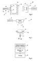
- the figure 3 schematically illustrates certain phenomena at the origin of the formation of artifacts that can be observed on the images acquired by the sensor 16 of the device 12 of the figure 2 .
- the support 30 is shown in lateral section.
- the incident light beam 15 has an opening angle and is schematically represented a light ray 40 of the incident beam 15 substantially perpendicular to the wall 32 and rays 42, 44 of the incident beam 15 inclined relative to the axis of the wall 32
- the light beam 40 passes through the support 30 without disturbance until reaching the scattering medium 18 to be analyzed.
- a first type of artifact results from light rays that directly reach the sensor 16 without having passed through the medium to be analyzed.
- This can result from an optical guidance of inclined spokes 42, 44 by the walls of the support 30.
- the inclined spokes 42 can be guided by the side wall 32 and the bottom 34 of the support 30, then escape from the support 30 and reach the sensor 16 directly without having passed through the scattering medium 18.
- the intensity of the light rays 42 that directly reach the sensor 16 may be significantly higher than that of diffuse radiation. Since the sensor 16 is generally adapted to the detection of low-intensity diffuse radiation, the fact that the light rays 42 reach the sensor 16 directly can lead to a saturation of the latter, rendering the acquired images unusable.
- fluorescence optical diffuse optical tomography may also use the image of diffuse radiation emitted by the scattering medium at the wavelength of the incident beam for calibration purposes.
- a second type of artefact results from defects 46 (inclusions, scratches, cracks, etc.) of the support 30. Indeed, when the light rays 44, optically guided by the wall 32, reach the defect 46, it can emit by reflection, refraction or diffraction a light beam 48. The defect 46 is then equivalent to a parasitic light source contributing to the radiation emitted by the scattering medium.
- the second type of artifact can be just as penalizing as the first type of artifact since it disturbs the analysis of the detected images insofar as the image processing algorithms provided by the sensor 16 are based on the assumption that the The properties of the illumination of the scattering medium 18 are well known, this illumination being able to result from a single source 14, from several point light sources, from extended sources, etc. In addition, since the distribution of these parasitic sources is not known, it is difficult to take them into account. This type of artifact can also occur for the optical device 10 shown in FIG. figure 1 .
- the present invention provides for using a diffusing material to carry out the support of the medium to be analyzed optically.
- the light rays of the incident beam diffusing as soon as they progress in the support, one observes a very fast attenuation of the light rays which tend to be guided optically by the support.
- This makes it possible to strongly reduce, or even to cancel, the proportion of light rays that can be guided optically by the support until it leaves the latter and reaches the image sensor directly or until the defects of the support are reached. which would behave like parasitic light sources.
- the diffusion coefficient of the material constituting the support is not chosen to be too high so as not to cause excessive attenuation of the diffuse radiation emitted by the scattering medium.
- the figure 4 represents a first embodiment of an optical device 49 according to the invention.
- the optical device 49 comprises the same elements as the device 12 shown in FIG. figure 3 with the difference that it comprises a support 50 consisting of a diffusing material.
- the lines 52 schematically denote the region of diffusion of the incident light beam 15 reaching the support 50.
- the support 50 has a tubular shape.
- the support 50 may have another shape and, for example, comprise two parallel plates, as for the optical device 10 shown in FIG. figure 1 .
- Such a support may also be applied against all or part of a surface of a scattering medium to be analyzed, without necessarily containing or supporting the scattering object to be analyzed in a given position.
- the objective is then to achieve a diffusion of the incident light produced by a light source placed at a distance from the support, providing the advantages described below.
- the support may be called diffusing intermediate medium, the intermediate adjective showing an arrangement between an external light source and the scattering medium to be analyzed.
- this support will be placed in contact with the surface of the diffusing medium, so as to constitute, with the scattering medium, a single diffusing assembly.
- the figure 5 represents a second embodiment of an optical device 54 according to the invention.
- the optical device 56 comprises the same elements as the device 10 shown in FIG. figure 3 with the difference that it comprises a support 56 consisting of a diffusing material and having the shape of a cradle in which is placed the scattering medium 18 to be analyzed.
- the shape of the support 56 is advantageously adapted to the diffusing medium 18. This makes it possible to reduce the possibilities of movement of the diffusing medium during the analysis, in particular when the diffusing medium is an animal or a being. human.
- the support itself is a diffusing object, it forms with the scattering medium to be analyzed a diffusing system whose external surface is precisely known since it corresponds to the external surface of the support. Since this surface may correspond to a simple geometrical shape, the resolution of the equations of propagation of light in the diffusing media can be simplified.
- Such a support makes it possible to reduce the surface luminous intensity on the surface of the diffusing medium.
- the invention will be of interest when the diffusing medium is a biological tissue and the light source is a laser source delivering an intense beam. In such a case, the incident beam, without prior diffusion, could generate lesions, such as burns, on the surface of the scattering medium analyzed.
- the incident beam is diffused before reaching the surface of the scattering medium, thus reducing the risk of lesion. It is then possible to increase the intensity of the incident ray, therefore the amount of light entering the diffusing medium, because of the light scattering upstream of the surface of the scattering medium.
- the optical diffusion properties and, in addition, optionally of absorption, of the support may be chosen close to those of the scattering medium to be analyzed.
- the reduced diffusion coefficient ⁇ s ' sup the material constituting the support is greater than 0.1 cm -1 and is preferably between 1 and 700 cm -1 .
- the absorption coefficient ⁇ at ' sup the material constituting the support may vary between 0 and 300 cm -1 and is preferably between 0.01 and 300 cm -1 .
- the support may consist entirely of a diffusing and optionally absorbent material. However, only one or more parts of the support may consist of the diffusing material, and possibly absorbent, the rest of the support being made of a substantially non-absorbent and non-diffusing material.
- the scattering portions are then advantageously provided at suitable locations of the support to prevent optical guiding phenomena from causing the formation of artifacts on the images acquired by the image sensor.
- the support according to the present invention can be used with an optical device in which the diffusing medium is immersed in an index matching liquid.
- the figure 6 represents in the form of a block diagram an example of a method of manufacturing a diffusing medium according to the invention.
- both the diffusion and absorption properties of the support are imposed.
- the diffusion properties of the support are established by the addition of diffusing particles, for example titanium dioxide particles, to an initially non-absorbent and non-diffusing material.
- the absorption properties of the support are established by adding an ink to the initial material, for example an ink marketed by Dabe under the name LOTUS Chinese Ink.
- the initial material is, for example, a non-absorbing and non-diffusing epoxy resin.
- the process begins at step 60 by preparing the amount of ink and the amount of titanium dioxide powder to be used.
- a reference absorbent solution containing ink diluted in ethanol.
- V T the volume of resin to be used
- ⁇ a (ref) corresponds to the absorption coefficient of the reference absorbent solution.
- the coefficient ⁇ a (ref) is, for example, measured beforehand using a spectrophotometer.
- C ref is the concentration of titanium dioxide particles in a reference diffusion solution
- ⁇ s ' ref is the reduced diffusion coefficient obtained for said reference solution.
- the reduced diffusion coefficient can be measured beforehand by diffuse reflectivity methods or time-resolved methods, for example the methods described in the publication of SL Jacques entitled “Time-resolved reflectance spectroscopy in turbid tissues" (IEEE Transactions on Biomedical Engineering 36, 1155-1161 (1989)). )).
- step 60 the ink volume V is taken from the reference absorbent solution and the volume taken is placed in a vial.
- the mass m of titanium dioxide is weighed and poured into the vial.
- the assembly can be placed in an ultrasonic bath to promote the elimination of possible aggregates.
- the process continues in step 62.
- step 62 the solution containing the ink and the titanium dioxide is mixed with the volume V T of resin.
- a resin consisting of a base and a catalyst
- the solution containing the ink and the titanium dioxide is mixed with the volume V T of resin.
- the vial containing the ink and the titanium dioxide can be rinsed with ethanol.
- the enclosure containing the resin-ink-titanium dioxide mixture is shaken to homogenize the assembly and can be placed in an ultrasonic bath. The process continues at step 64.
- step 64 the resin-ink-titanium dioxide mixture is placed in a mold adapted to the desired shape of the support.
- the resin can be allowed to polymerize at room temperature.
- a final step of machining the support may optionally be provided.
Landscapes
- Health & Medical Sciences (AREA)
- Life Sciences & Earth Sciences (AREA)
- Physics & Mathematics (AREA)
- Pathology (AREA)
- General Health & Medical Sciences (AREA)
- Analytical Chemistry (AREA)
- Chemical & Material Sciences (AREA)
- Immunology (AREA)
- General Physics & Mathematics (AREA)
- Biochemistry (AREA)
- Nuclear Medicine, Radiotherapy & Molecular Imaging (AREA)
- Medical Informatics (AREA)
- Surgery (AREA)
- Animal Behavior & Ethology (AREA)
- Radiology & Medical Imaging (AREA)
- Public Health (AREA)
- Veterinary Medicine (AREA)
- Molecular Biology (AREA)
- Biophysics (AREA)
- Heart & Thoracic Surgery (AREA)
- Biomedical Technology (AREA)
- Engineering & Computer Science (AREA)
- Optics & Photonics (AREA)
- Investigating Or Analysing Materials By Optical Means (AREA)
Abstract
Description
- La présente invention concerne un dispositif optique pour l'analyse d'un milieu diffusant maintenu par un support.
- Un domaine de l'imagerie optique concerne l'analyse d'un milieu diffusant, par exemple l'analyse de tissus biologiques.
- De façon générale, le milieu diffusant est soumis à un faisceau lumineux incident. Pour certaines applications, par exemple en tomographie optique diffusive, la longueur d'onde du faisceau incident est dans le spectre visible, de façon classique dans le rouge ou dans le proche infrarouge, ce qui correspond à la plage de longueurs d'onde où l'absorption des tissus biologiques est minimale. Le faisceau lumineux incident diffuse dans le milieu diffusant et le rayonnement lumineux diffus qui s'échappe du milieu diffusant est détecté par un capteur, par exemple une caméra. Les images fournies par le capteur sont analysées pour déterminer les propriétés optiques du milieu diffusant, par exemple pour déterminer la distribution des propriétés optiques de diffusion et/ou d'absorption du milieu diffusant, par exemple pour détecter la présence d'une zone anormalement absorbante et/ou diffusante.
- Pour d'autres applications, par exemple en tomographie optique diffusive de fluorescence, on dispose dans le milieu diffusant des marqueurs fluorescents spécifiques qui tendent à se concentrer dans des zones d'intérêt. Lorsqu'ils sont éclairés par le faisceau lumineux incident, les marqueurs émettent un rayonnement à une longueur d'onde distincte de celle du faisceau incident. Ce rayonnement diffuse dans le milieu diffusant et est détecté et analysé pour déterminer les propriétés des marqueurs (par exemple, la localisation et la concentration locale des marqueurs).
- Dans le domaine de l'imagerie médicale, les techniques d'imagerie optique offrent, par exemple pour la détection et la localisation de tumeurs cancéreuses, une alternative aux techniques d'imagerie classiques telles que la radiographie et tomographie par rayons X, la tomographie par émission de positons, l'imagerie par résonance magnétique, etc.
- Pour certains dispositifs optiques, la source lumineuse est en contact direct avec le milieu diffusant. A titre d'exemple, le faisceau lumineux incident est guidé jusqu'au milieu diffusant par des fibres optiques. Le rayonnement diffus émis par le milieu diffusant peut également être récupéré par des fibres optiques et guidé jusqu'au capteur. Un avantage est que l'environnement du milieu diffusant, en particulier le support maintenant le milieu diffusant, ne perturbe pas les mesures. Toutefois, ces dispositifs optiques sont généralement encombrants car la précision accessible de la distribution des propriétés optiques dépend du nombre de mesures indépendantes pouvant être effectuées, c'est-à-dire du nombre de fibres optiques utilisées.
- Pour d'autres dispositifs optiques, la source lumineuse est à distance du milieu diffusant. La structure du dispositif optique peut alors être simplifiée. Le support maintenant le milieu diffusant est généralement conçu de façon à perturber le moins possible la propagation des rayons lumineux. Pour ce faire, le support est constitué d'un matériau non absorbant et non diffusant pour la plage de longueurs d'onde utile.
- Les
figures 1 et 2 représentent deux exemples de réalisation de dispositifs optiques pour lesquels la source lumineuse est à distance du milieu diffusant. Chaque dispositif optique 10, 12 comprend une source lumineuse 14, par exemple une diode laser fournissant un faisceau lumineux monochromatique 15 dont la longueur d'onde est, par exemple, de 670 nanomètres, et un capteur d'images 16 adapté à la détection d'un rayonnement diffus. Un outil d'analyse 17 est relié au capteur 16 et réalise un traitement des images acquises par le capteur 16. Un milieu diffusant à analyser 18, par exemple une souris, est disposé de façon à recevoir le faisceau lumineux incident 15 fourni par la source lumineuse 14. Une lentille 19 est disposée entre le milieu diffusant 18 et le capteur 16. L'axe du capteur 16 peut ne pas être parallèle au faisceau incident 15. Selon une variante, les images fournies par le capteur 16 peuvent être enregistrées par l'outil 17 puis analysées ultérieurement au moyen d'un autre ordinateur. - Pour le dispositif 10 représenté en
figure 1 , le milieu 18 à analyser est maintenu par un support 20 comprenant une plaque d'entrée 22 située entre le milieu 18 et la source lumineuse 14 et une plaque 24 de sortie située entre le milieu 18 et le capteur 16. Les plaques 22, 24 sont transparentes et parallèles. A titre d'exemple, le support 20 peut être fixe et la source lumineuse 14 peut se déplacer par rapport au support 20. Pour le dispositif 12 représenté enfigure 2 , le milieu 18 à analyser est maintenu par un support 30 correspondant à un tube transparent comprenant une paroi latérale cylindrique 32 et un fond plan 34. A titre d'exemple, le support 20 est monté sur un bras rotatif 38, la source 14 pouvant être fixe. - Le support 20, 30 est de façon générale en plastique ou en verre. Toutefois, l'utilisation de tels supports peut entraîner la formation d'artefacts sur les images fournies par le capteur 16. Ces artefacts peuvent gêner voire empêcher l'analyse du milieu diffusant 18.
- La présente invention vise un dispositif optique pour l'analyse d'un milieu diffusant maintenu par un support comprenant une source lumineuse et un capteur, la source lumineuse étant à distance du milieu à analyser, le support permettant de réduire, voire de supprimer, la formation d'artefacts sur les images acquises par le capteur.
- Une autre caractéristique du support est qu'il peut être fabriqué simplement.
- Une autre caractéristique est que les propriétés optiques du support varient peu dans le temps.
- Ainsi, un mode de réalisation de la présente invention prévoit un dispositif optique destiné à l'analyse d'un milieu diffusant. Le dispositif comprend au moins une source lumineuse à distance du milieu diffusant et adaptée à fournir un faisceau lumineux incident destiné à éclairer le milieu diffusant ; au moins un capteur adapté à détecter un rayonnement émis par le milieu diffusant ; un support du milieu diffusant au moins partiellement non absorbant pour le faisceau lumineux incident et le rayonnement diffus. Tout ou partie du support est constitué d'un matériau diffusant dont le coefficient de diffusion réduit est supérieur à 0,1 cm-1 et inférieur à 700 cm-1.
- Selon un mode de réalisation de l'invention, le coefficient de diffusion réduit du support est compris entre 1 et 700 cm-1.
- Selon un mode de réalisation de l'invention, ledit matériau a un coefficient d'absorption compris entre 0.01 et 300 cm-1.
- Selon un mode de réalisation de l'invention, le support comprend au moins une paroi destinée à être située entre la source et le milieu diffusant et/ou entre le milieu diffusant et le capteur.
- Selon un mode de réalisation de l'invention, le support a la forme d'un berceau destiné à recevoir le milieu diffusant.
- Un mode de réalisation de l'invention prévoit un support adapté au dispositif optique décrit précédemment.
- Un mode de réalisation de l'invention prévoit une utilisation du dispositif optique décrit précédemment, pour réaliser par tomographie une cartographie à trois dimensions du coefficient d'absorption et/ou du coefficient de diffusion réduit du milieu diffusant.
- Un mode de réalisation de l'invention prévoit une utilisation du dispositif optique décrit précédemment, le faisceau lumineux incident étant à une première longueur d'onde, l'utilisation consistant à placer dans le milieu diffusant des fluorophores sensibles à la première longueur d'onde et émettant le rayonnement diffus à une seconde longueur d'onde, le capteur fournissant des images utilisées pour déterminer des propriétés des fluorophores et/ou des propriétés du milieu diffusant.
- Un mode de réalisation de l'invention prévoit un procédé de fabrication du support décrit précédemment. Le procédé comprend les étapes consistant à préparer une poudre d'un matériau diffusant ; à mélanger la poudre à une solution d'un matériau sensiblement non absorbant, non diffusant et durcissable ; et à injecter le mélange obtenu dans un moule pour former le support.
- Selon un mode de réalisation de l'invention, le procédé comprend, en outre, l'étape consistant à mélanger une solution supplémentaire d'un matériau absorbant à la poudre ou à la solution.
- Ces objets, caractéristiques et avantages, ainsi que d'autres seront exposés en détail dans la description suivante d'un exemple de réalisation particulier faite à titre non-limitatif en relation avec les figures jointes parmi lesquelles :
- les
figures 1 et 2 , précédemment décrites, représentent, de façon schématique, des exemples classiques de dispositifs optiques pour l'analyse d'un milieu diffusant ; - la
figure 3 illustre de façon schématique certains artefacts pouvant être observés avec le dispositif de lafigure 2 ; - les
figures 4 et 5 représentent de façon schématique des premier et second exemples de dispositifs optiques selon un mode de réalisation de l'invention ; et - la
figure 6 représente, sous la forme d'un schéma par blocs, un exemple de procédé de fabrication d'un support de dispositif optique selon un mode de réalisation de l'invention. - Par souci de clarté, de mêmes éléments ont été désignés par de mêmes références aux différentes figures.
- La Demanderesse est parvenue à la présente invention par une analyse des phénomènes à l'origine de la formation d'artefacts sur les images fournies par le capteur d'un dispositif optique pour l'analyse d'un milieu diffusant.
- La
figure 3 illustre de façon schématique certains phénomènes à l'origine de la formation d'artefacts pouvant être observés sur les images acquises par le capteur 16 du dispositif 12 de lafigure 2 . Enfigure 3 , le support 30 est représenté en coupe latérale. Le faisceau lumineux incident 15 présente un angle d'ouverture et on a schématiquement représenté un rayon lumineux 40 du faisceau incident 15 sensiblement perpendiculaire à la paroi 32 et des rayons 42, 44 du faisceau incident 15 inclinés par rapport l'axe de la paroi 32. Le rayon lumineux 40 traverse sans perturbation le support 30 jusqu'à atteindre le milieu diffusant 18 à analyser. - Un premier type d'artefact résulte de rayons lumineux qui atteignent directement le capteur 16 sans avoir traversé le milieu à analyser. Ceci peut résulter d'un guidage optique de rayons inclinés 42, 44 par les parois du support 30. A titre d'exemple, les rayons inclinés 42 peuvent être guidés par la paroi latérale 32 et le fond 34 du support 30, puis s'échapper du support 30 et atteindre directement le capteur 16 sans avoir traversé le milieu diffusant 18. L'intensité des rayons lumineux 42 qui atteignent directement le capteur 16 peut être nettement supérieure à celle du rayonnement diffus. Le capteur 16 étant généralement adapté à la détection d'un rayonnement diffus de faible intensité, le fait que les rayons lumineux 42 atteignent directement le capteur 16 peut entraîner une saturation de ce dernier, ce qui rend inutilisables les images acquises. On pourrait considérer que les phénomènes décrits précédemment ne sont pas pénalisants pour la tomographie optique diffusive de fluorescence pour laquelle on détecte une image du rayonnement diffus émis par les marqueurs fluorescents à une longueur d'onde différente de la longueur d'onde du faisceau lumineux incident. Toutefois, la tomographie optique diffusive de fluorescence peut aussi utiliser l'image du rayonnement diffus émis par le milieu diffusant à la longueur d'onde du faisceau incident à des fins d'étalonnage.
- Un second type d'artefact résulte de défauts 46 (inclusions, rayures, fissures, etc.) du support 30. En effet, lorsque les rayons lumineux 44, guidés optiquement par la paroi 32, atteignent le défaut 46, celui-ci peut émettre, par réflexion, réfraction ou diffraction un faisceau lumineux 48. Le défaut 46 est alors équivalent à une source lumineuse parasite contribuant au rayonnement émis par le milieu diffusant. Le second type d'artefacts peut être tout aussi pénalisant que le premier type d'artefact puisqu'il perturbe l'analyse des images détectées dans la mesure où les algorithmes de traitement des images fournies par le capteur 16 partent de l'hypothèse que les propriétés de l'illumination du milieu diffusant 18 sont bien connues, cette illumination pouvant résulter d'une source unique 14, de plusieurs sources lumineuses ponctuelles, de sources étendues, etc. En outre, la répartition de ces sources parasites n'étant pas connue, il s'avère difficile de les prendre en compte. Ce type d'artefact peut se produire aussi pour le dispositif optique 10 représenté en
figure 1 . - La présente invention prévoit d'utiliser un matériau diffusant pour réaliser le support du milieu à analyser optiquement. Les rayons lumineux du faisceau incident diffusant dès qu'ils progressent dans le support, on observe une atténuation très rapide des rayons lumineux qui tendent à être guidés optiquement par le support. Ceci permet de réduire fortement, voire d'annuler, la proportion de rayons lumineux susceptibles d'être guidés optiquement par le support jusqu'à sortir de celui-ci et atteindre directement le capteur d'images ou jusqu'à atteindre des défauts du support qui se comporteraient comme des sources lumineuses parasites. Le coefficient de diffusion du matériau constituant le support n'est toutefois pas choisi trop élevé pour ne pas entraîner une atténuation trop importante du rayonnement diffus émis par le milieu diffusant.
- La
figure 4 représente un premier exemple de réalisation d'un dispositif optique 49 selon l'invention. Le dispositif optique 49 comprend les mêmes éléments que le dispositif 12 représenté enfigure 3 à la différence qu'il comporte un support 50 constitué d'un matériau diffusant. Les traits 52 désignent de façon schématique la région de diffusion du faisceau lumineux incident 15 atteignant le support 50. Dans l'exemple de réalisation représenté enfigure 3 , le support 50 a une forme tubulaire. Toutefois, le support 50 peut avoir une autre forme et, par exemple, comprendre deux plaques parallèles, comme pour le dispositif optique 10 représenté enfigure 1 . - Un tel support peut également être appliqué contre tout ou partie d'une surface d'un milieu diffusant à analyser, sans nécessairement contenir ni supporter l'objet diffusant à analyser dans une position donnée. L'objectif est alors d'aboutir à une diffusion de la lumière incidente produite par une source de lumière placée à distance du support, en procurant les avantages décrits ci après. Dans une telle configuration, le support pourra être appelé milieu intercalaire diffusant, l'adjectif intercalaire montrant bien une disposition entre une source de lumière externe et le milieu diffusant à analyser. Préférentiellement, ce support sera placé au contact de la surface du milieu diffusant, afin de constituer, avec le milieu diffusant, un unique ensemble diffusant.
- La
figure 5 représente un second exemple de réalisation d'un dispositif optique 54 selon l'invention. Le dispositif optique 56 comprend les mêmes éléments que le dispositif 10 représenté enfigure 3 à la différence qu'il comporte un support 56 constitué d'un matériau diffusant et ayant la forme d'un berceau dans lequel est placé le milieu diffusant 18 à analyser. Dans le présent exemple de réalisation, la forme du support 56 est avantageusement adaptée au milieu diffusant 18. Ceci permet de réduire les possibilités de mouvement du milieu diffusant au cours de l'analyse, en particulier lorsque le milieu diffusant est un animal ou un être humain. - Le support étant lui-même un objet diffusant, il forme avec le milieu diffusant à analyser un système diffusant dont la surface externe est connue avec précision puisqu'elle correspond à la surface externe du support. Cette surface pouvant correspondre à une forme géométrique simple, la résolution des équations de propagation de la lumière dans les milieux diffusants peut être simplifiée.
- Un autre avantage d'un tel support est de produire une diffusion de la lumière produite par le faisceau incident avant que cette dernière n'atteigne le milieu diffusant à analyser. La diffusion du faisceau incident dans le support entraîne un élargissement de la surface du milieu diffusant impactée par ce faisceau. Ainsi, un tel support permet de réduire l'intensité lumineuse surfacique à la surface du milieu diffusant. L'invention trouvera son intérêt lorsque le milieu diffusant est un tissu biologique et que la source lumineuse est une source Laser délivrant un faisceau intense. Dans un tel cas, le faisceau incident, sans diffusion préalable, pourrait générer des lésions, telles des brûlures, à la surface du milieu diffusant analysé. En présence du support objet de l'invention, le faisceau incident subit une diffusion avant d'atteindre la surface du milieu diffusant, réduisant ainsi le risque de lésion. Il est alors possible d'augmenter l'intensité du rayon incident, donc la quantité de lumière pénétrant dans le milieu diffusant, du fait de la diffusion de lumière en amont de la surface du milieu diffusant.
- De façon avantageuse, pour améliorer le couplage optique entre le support et le milieu diffusant et donc faciliter la modélisation de la propagation des rayons lumineux dans le système diffusant composé du support diffusant et du milieu diffusant, les propriétés optiques de diffusion et, en outre, éventuellement d'absorption, du support peuvent être choisies proches de celles du milieu diffusant à analyser. Le coefficient de diffusion réduit


- Le support peut être constitué en totalité d'un matériau diffusant et éventuellement absorbant. Toutefois, seule une ou plusieurs parties du support peuvent être constituées du matériau diffusant, et éventuellement absorbant, le reste du support étant constitué d'un matériau sensiblement non absorbant et non diffusant. Les portions diffusantes sont alors avantageusement prévues à des emplacements adaptés du support pour éviter que des phénomènes de guidage optique n'entraînent la formation d'artefacts sur les images acquises par le capteur d'images. Le support selon la présente invention peut être utilisé avec un dispositif optique dans lequel le milieu diffusant baigne dans un liquide d'adaptation d'indices.
- Le fait d'utiliser un matériau diffusant pour réaliser le support permet d'assurer que les propriétés optiques du support évoluent peu dans le temps. En effet, pour supprimer la formation d'artefacts sur les images fournies par le capteur du dispositif optique, on aurait pu utiliser un support non diffusant dont on aurait dépoli certaines faces. Toutefois, un tel traitement de surface peut être difficile à mettre en oeuvre, en particulier lorsque le support comprend des portions non planes. En outre, le dépolissage peut se dégrader avec le temps. En particulier, le dépolissage peut être abîmé lors de chocs qui se traduisent par des défauts à la surface du support entraînant la formation d'artefacts sur les images acquises par le capteur 16.
- La
figure 6 représente sous la forme d'un schéma par blocs un exemple de procédé de fabrication d'un support diffusant selon l'invention. Dans le présent exemple de réalisation, on impose à la fois les propriétés de diffusion et d'absorption du support. Les propriétés de diffusion du support sont établies par l'ajout de particules diffusantes, par exemple des particules de dioxyde de titane, à un matériau initialement non absorbant et non diffusant. Les propriétés d'absorption du support sont établies par l'ajout d'une encre au matériau initial, par exemple une encre commercialisée par la société Dabe sous l'appellation Encre de Chine LOTUS. Le matériau initial est, par exemple, une résine époxy non absorbante et non diffusante. - Le procédé commence à l'étape 60 par la préparation de la quantité d'encre et de la quantité de poudre de dioxyde de titane à utiliser. Pour ce faire, on peut utiliser une solution absorbante de référence, contenant de l'encre diluée dans de l'éthanol. En appelant VT le volume de résine à utiliser, le volume Vencre de la solution absorbante de référence à utiliser pour obtenir le coefficient d'absorption µa(sup) souhaité est donné par la relation suivante :

où µa(ref) correspond au coefficient d'absorption de la solution absorbante de référence. Le coefficient µa(ref) est, par exemple, mesuré au préalable à l'aide d'un spectrophotomètre. - En appelant


où Cref est la concentration de particules de dioxyde de titane dans une solution diffusante de référence et
- A titre d'exemple, on considère une solution absorbante de référence ayant une concentration d'encre de 1 % dont le coefficient d'absorption µa(ref) pour la longueur d'onde de 633 nm est de l'ordre de 30 cm-1 et une solution diffusante de référence ayant une concentration Cref de dioxyde de titane de 10 mg/ml et pour laquelle le coefficient de diffusion réduit


- A l'étape 60, on prélève le volume Vencre de la solution absorbante de référence et on met le volume prélevé dans une fiole. La masse m de dioxyde de titane est pesée et versée dans la fiole. L'ensemble peut être placé dans un bain à ultrasons pour favoriser l'élimination d'éventuels agrégats. Le procédé se poursuit à l'étape 62.
- A l'étape 62, on mélange la solution contenant l'encre et le dioxyde de titane au volume VT de résine. Une possibilité consiste dans le cas d'une résine constituée d'une base et d'un catalyseur, à mélanger en premier lieu la base et le catalyseur et à attendre un peu avant d'ajouter la solution contenant l'encre et le dioxyde de titane. Une autre possibilité consiste à incorporer la solution contenant l'encre et le dioxyde de titane à la base et à ajouter le catalyseur de la résine par la suite. La fiole contenant l'encre et le dioxyde de titane peut être rincée avec de l'éthanol. L'enceinte contenant le mélange résine-encre-dioxyde de titane est secouée pour homogénéiser l'ensemble et peut être placée dans un bain à ultrasons. Le procédé se poursuit à l'étape 64.
- A l'étape 64, le mélange résine-encre-dioxyde de titane est placé dans un moule adapté à la forme souhaitée du support. On peut laisser polymériser la résine à température ambiante. Après refroidissement et démoulage, une étape finale d'usinage du support peut éventuellement être prévue.
Claims (11)
- Dispositif optique (49 ; 54) destiné à l'analyse de la lumière diffuse émise par un milieu diffusant (18), comprenant :au moins une source lumineuse (14) à distance du milieu diffusant et adaptée à fournir un faisceau lumineux incident (15) destiné à éclairer le milieu diffusant ;au moins un capteur (16) adapté à détecter un rayonnement émis par le milieu diffusant ;un support (50 ; 56) du milieu diffusant au moins partiellement non absorbant pour le faisceau lumineux incident et le rayonnement diffus,caractérisé en ce que tout ou partie du support est constitué d'un matériau diffusant dont le coefficient de diffusion réduit est supérieur à 0,1 cm-1 et inférieur à 700 cm-1.
- Dispositif optique selon la revendication 1, dans lequel le coefficient de diffusion réduit du support (50 ; 56) est compris entre 1 et 700 cm-1.
- Dispositif optique selon la revendication 1 ou 2, dans lequel ledit matériau a un coefficient d'absorption compris entre 0.01 et 300 cm-1.
- Dispositif optique selon l'une quelconque des revendications précédentes, dans lequel le matériau diffusant du support est sélectionné pour avoir des propriétés optiques de diffusion et d'absorption voisines de celles du milieu diffusant à analyser.
- Dispositif optique selon l'une quelconque des revendications précédentes, dans lequel le support (50 ; 56) comprend au moins une paroi destinée à être située entre la source et le milieu diffusant et/ou entre le milieu diffusant et le capteur (16).
- Dispositif selon l'une quelconque des revendications précédentes, dans lequel le support (50 ; 56) a la forme d'un berceau destiné à recevoir le milieu diffusant (18).
- Support (50 ; 56) d'un milieu diffusant (18) adapté à un dispositif optique destiné à l'analyse du milieu diffusant, caractérisé en ce qu'il est constitué, tout ou partie, d'un matériau diffusant dont le coefficient de diffusion réduit est supérieur à 0,1 cm-1 et inférieur à 700 cm-1.
- Utilisation du dispositif optique (49 ; 54) selon l'une quelconque des revendications 1 à 6, pour réaliser par tomographie une cartographie à trois dimensions du coefficient d'absorption et/ou du coefficient de diffusion réduit du milieu diffusant (18).
- Utilisation du dispositif optique (49 ; 54) selon l'une quelconque des revendications 1 à 6, le faisceau lumineux incident (15) étant à une première longueur d'onde, l'utilisation consistant à placer dans le milieu diffusant (18) des fluorophores sensibles à la première longueur d'onde et émettant le rayonnement diffus à une seconde longueur d'onde, le capteur fournissant des images utilisées pour déterminer des propriétés des fluorophores et/ou des propriétés du milieu diffusant.
- Procédé de fabrication d'un support (50 ; 56) selon la revendication 7, comprenant les étapes suivante :préparer une poudre d'un matériau diffusant ;mélanger la poudre à une solution d'un matériau sensiblement non absorbant, non diffusant et durcissable ; etinjecter le mélange obtenu dans un moule pour former le support.
- Procédé selon la revendication 10, comprenant en outre l'étape consistant à mélanger à la poudre ou à la solution une solution supplémentaire d'un matériau absorbant.
Applications Claiming Priority (1)
| Application Number | Priority Date | Filing Date | Title |
|---|---|---|---|
| FR0852633A FR2930343B1 (fr) | 2008-04-18 | 2008-04-18 | Dispositif optique pour l'analyse d'un milieu diffusant maintenu par un support |
Publications (1)
| Publication Number | Publication Date |
|---|---|
| EP2110657A1 true EP2110657A1 (fr) | 2009-10-21 |
Family
ID=40070578
Family Applications (1)
| Application Number | Title | Priority Date | Filing Date |
|---|---|---|---|
| EP09158148A Ceased EP2110657A1 (fr) | 2008-04-18 | 2009-04-17 | Dispositif optique pour l'analyse d'un milieu diffusant maintenu par un support |
Country Status (3)
| Country | Link |
|---|---|
| US (1) | US8120784B2 (fr) |
| EP (1) | EP2110657A1 (fr) |
| FR (1) | FR2930343B1 (fr) |
Families Citing this family (19)
| Publication number | Priority date | Publication date | Assignee | Title |
|---|---|---|---|---|
| US7884933B1 (en) * | 2010-05-05 | 2011-02-08 | Revolutionary Business Concepts, Inc. | Apparatus and method for determining analyte concentrations |
| JP5648957B2 (ja) | 2010-10-22 | 2015-01-07 | 浜松ホトニクス株式会社 | 乳房計測装置 |
| CN103712925B (zh) * | 2013-12-26 | 2015-09-23 | 天津大学 | 用于采集散射介质中径向扩散反射光的多路光纤锥套装置 |
| CN105277497A (zh) * | 2015-11-06 | 2016-01-27 | 浙江大学 | 连续光谱下检测农产品的光学特性参数的装置与方法 |
| US9730649B1 (en) | 2016-09-13 | 2017-08-15 | Open Water Internet Inc. | Optical imaging of diffuse medium |
| FR3076351A1 (fr) * | 2017-12-28 | 2019-07-05 | Commissariat A L'energie Atomique Et Aux Energies Alternatives | Dispositif d'analyse d'un echantillon |
| US10778911B2 (en) | 2018-03-31 | 2020-09-15 | Open Water Internet Inc. | Optical transformation device for imaging |
| US10778912B2 (en) | 2018-03-31 | 2020-09-15 | Open Water Internet Inc. | System and device for optical transformation |
| US10506181B2 (en) | 2018-03-31 | 2019-12-10 | Open Water Internet Inc. | Device for optical imaging |
| US10966612B2 (en) | 2018-06-14 | 2021-04-06 | Open Water Internet Inc. | Expanding beam optical element |
| US10962929B2 (en) | 2018-09-14 | 2021-03-30 | Open Water Internet Inc. | Interference optics for optical imaging device |
| US10874370B2 (en) | 2019-01-28 | 2020-12-29 | Open Water Internet Inc. | Pulse measurement in optical imaging |
| US10955406B2 (en) | 2019-02-05 | 2021-03-23 | Open Water Internet Inc. | Diffuse optical imaging with multiple beams |
| US11320370B2 (en) | 2019-06-26 | 2022-05-03 | Open Water Internet Inc. | Apparatus for directing optical and acoustic signals |
| US11581696B2 (en) | 2019-08-14 | 2023-02-14 | Open Water Internet Inc. | Multi-channel laser |
| US11622686B2 (en) | 2019-11-22 | 2023-04-11 | Open Water Internet, Inc. | Optical imaging with unshifted reference beam |
| US11819318B2 (en) | 2020-04-27 | 2023-11-21 | Open Water Internet Inc. | Optical imaging from light coherence |
| US11559208B2 (en) | 2020-05-19 | 2023-01-24 | Open Water Internet Inc. | Imaging with scattering layer |
| US11259706B2 (en) | 2020-05-19 | 2022-03-01 | Open Water Internet Inc. | Dual wavelength imaging and out of sample optical imaging |
Citations (5)
| Publication number | Priority date | Publication date | Assignee | Title |
|---|---|---|---|---|
| WO1999040411A1 (fr) * | 1998-02-10 | 1999-08-12 | Daedalus I, Llc | APPAREIL POUR LA DETERMINATION DU pH, pCO2, DE L'HEMOGLOBINE ET DE LA SATURATION EN OXYGENE DE L'HEMOGLOBINE |
| WO2002042824A2 (fr) * | 2000-11-24 | 2002-05-30 | P.A.L.M. Microlaser Technologies Ag | Receptacle destine a recevoir un objet devant etre etudie au microscope, en particulier un objet biologique |
| WO2002095476A2 (fr) * | 2001-05-22 | 2002-11-28 | Medical Research Council | Etage rotatif pour l'imagerie d'echantillon |
| US20040015062A1 (en) * | 2000-11-27 | 2004-01-22 | Vasilis Ntziachristos | Fluorescence-mediated molecular tomography |
| WO2007057798A2 (fr) * | 2005-11-18 | 2007-05-24 | Koninklijke Philips Electronics N.V. | Dispositif d’imagerie de l’intérieur d’un milieu trouble |
Family Cites Families (7)
| Publication number | Priority date | Publication date | Assignee | Title |
|---|---|---|---|---|
| FI834756A0 (fi) * | 1983-12-22 | 1983-12-22 | Labsystems Oy | Kyvettenhet |
| JP3006123B2 (ja) * | 1991-03-18 | 2000-02-07 | ソニー株式会社 | 動脈硬さ観測装置 |
| JP2002501803A (ja) * | 1998-02-05 | 2002-01-22 | イン−ラインダイアグノスティックスコーポレイション | 非観血的血液成分モニタ方法および装置 |
| US6353226B1 (en) * | 1998-11-23 | 2002-03-05 | Abbott Laboratories | Non-invasive sensor capable of determining optical parameters in a sample having multiple layers |
| US6475800B1 (en) * | 1999-07-22 | 2002-11-05 | Instrumentation Metrics, Inc. | Intra-serum and intra-gel for modeling human skin tissue |
| US7322972B2 (en) * | 2002-04-10 | 2008-01-29 | The Regents Of The University Of California | In vivo port wine stain, burn and melanin depth determination using a photoacoustic probe |
| US7400754B2 (en) * | 2003-04-08 | 2008-07-15 | The Regents Of The University Of California | Method and apparatus for characterization of chromophore content and distribution in skin using cross-polarized diffuse reflectance imaging |
-
2008
- 2008-04-18 FR FR0852633A patent/FR2930343B1/fr active Active
-
2009
- 2009-04-17 US US12/425,558 patent/US8120784B2/en active Active
- 2009-04-17 EP EP09158148A patent/EP2110657A1/fr not_active Ceased
Patent Citations (5)
| Publication number | Priority date | Publication date | Assignee | Title |
|---|---|---|---|---|
| WO1999040411A1 (fr) * | 1998-02-10 | 1999-08-12 | Daedalus I, Llc | APPAREIL POUR LA DETERMINATION DU pH, pCO2, DE L'HEMOGLOBINE ET DE LA SATURATION EN OXYGENE DE L'HEMOGLOBINE |
| WO2002042824A2 (fr) * | 2000-11-24 | 2002-05-30 | P.A.L.M. Microlaser Technologies Ag | Receptacle destine a recevoir un objet devant etre etudie au microscope, en particulier un objet biologique |
| US20040015062A1 (en) * | 2000-11-27 | 2004-01-22 | Vasilis Ntziachristos | Fluorescence-mediated molecular tomography |
| WO2002095476A2 (fr) * | 2001-05-22 | 2002-11-28 | Medical Research Council | Etage rotatif pour l'imagerie d'echantillon |
| WO2007057798A2 (fr) * | 2005-11-18 | 2007-05-24 | Koninklijke Philips Electronics N.V. | Dispositif d’imagerie de l’intérieur d’un milieu trouble |
Non-Patent Citations (3)
| Title |
|---|
| DINTEN J.-M. ET AL: "Performance of different reflectance and diffuse optical imaging tomographic approaches in fluorescence molecular imaging of small animals", PROCEEDINGS OF SPIE. MEDICAL IMAGING 2006: PHYSICS OF MEDICAL IMAGING, vol. 6142, 2006, USA, pages 614215-1 - 614215-10, XP002507356 * |
| S. L. JACQUES: "Time- resolved reflectance spectroscopy in turbid tissues", IEEE TRANSACTIONS ON BIOMEDICAL ENGINEERING, vol. 36, 1989, pages 1155 - 1161 |
| SHARPE J: "Optical Projection Tomography", ANNU. REV. BIOMED. ENG., vol. 6, 9 April 2004 (2004-04-09), USA, pages 209 - 228, XP002507150 * |
Also Published As
| Publication number | Publication date |
|---|---|
| US20090262365A1 (en) | 2009-10-22 |
| US8120784B2 (en) | 2012-02-21 |
| FR2930343B1 (fr) | 2014-09-19 |
| FR2930343A1 (fr) | 2009-10-23 |
Similar Documents
| Publication | Publication Date | Title |
|---|---|---|
| EP2110657A1 (fr) | Dispositif optique pour l'analyse d'un milieu diffusant maintenu par un support | |
| EP2309249B1 (fr) | Dispositif et procédé pour l'excitation diffusée en imagerie | |
| US10024785B2 (en) | Solid hemoglobin-polymer biophotonic phantoms and their use | |
| EP0627620B1 (fr) | Procédé et dispositif pour déterminer une information interne dans un milieu diffusant | |
| US5529065A (en) | Method for measuring scattering medium and apparatus for the same | |
| EP3167285B1 (fr) | Dispositif non invasif de détermination de la fertilité et/ou du sexe d'un oeuf, et procédé correspondant | |
| CN1097729C (zh) | 利用散射光的测定方法及测定装置 | |
| Rajadhyaksha et al. | Detectability of contrast agents for confocal reflectance imaging of skin and microcirculation | |
| Šćepanović et al. | A multimodal spectroscopy system for real-time disease diagnosis | |
| Lapointe et al. | A multi-view time-domain non-contact diffuse optical tomography scanner with dual wavelength detection for intrinsic and fluorescence small animal imaging | |
| CN1342054A (zh) | 提供高对比度成像的方法和装置 | |
| JPH07209177A (ja) | 散乱吸収体計測方法及び散乱吸収体計測装置 | |
| CN1479864A (zh) | 特定成分信息测量装置 | |
| Moffitt et al. | Sized-fiber reflectometry for measuring local optical properties | |
| US8208982B2 (en) | Evanescent catheter system | |
| FR3032527A1 (fr) | Dispositif de mesure d'un signal optique retrodiffuse par un echantillon | |
| Lau et al. | Re-evaluation of model-based light-scattering spectroscopy for tissue spectroscopy | |
| Qu et al. | Excitation-and-collection geometry insensitive fluorescence imaging of tissue-simulating turbid media | |
| US7937226B2 (en) | Method and device for backscatter spectroscopy | |
| EP3502666A1 (fr) | Dispositif de mesure d'un rayonnement rétrodiffusé par un échantillon et procédé de mesure utilisant un tel dispositif | |
| Cao et al. | Lab-in-a-Phone: A lightweight oblique incidence reflectometer based on smartphone | |
| EP2021774B1 (fr) | Système comprenant un système d'éclairage alternant et un dispositif d'imagerie et procédé utilisant ledit système | |
| Wycoff et al. | In vitro Assessment of lesion activity using simultaneous time-resolved reflectance imaging at 1300 and 1950 nm | |
| Perekatova et al. | Fluence compensated optoacoustic measurements of blood oxygen saturation in vivo at two optimal wavelengths | |
| FR2531854A1 (fr) | Appareil de mesure non invasive de la vitesse moyenne du courant sanguin dans des tissus vivants |
Legal Events
| Date | Code | Title | Description |
|---|---|---|---|
| PUAI | Public reference made under article 153(3) epc to a published international application that has entered the european phase |
Free format text: ORIGINAL CODE: 0009012 |
|
| AK | Designated contracting states |
Kind code of ref document: A1 Designated state(s): AT BE BG CH CY CZ DE DK EE ES FI FR GB GR HR HU IE IS IT LI LT LU LV MC MK MT NL NO PL PT RO SE SI SK TR |
|
| RAP1 | Party data changed (applicant data changed or rights of an application transferred) |
Owner name: COMMISSARIAT A L'ENERGIE ATOMIQUE ET AUX ENERGIES |
|
| 17P | Request for examination filed |
Effective date: 20100420 |
|
| STAA | Information on the status of an ep patent application or granted ep patent |
Free format text: STATUS: EXAMINATION IS IN PROGRESS |
|
| 17Q | First examination report despatched |
Effective date: 20170425 |
|
| STAA | Information on the status of an ep patent application or granted ep patent |
Free format text: STATUS: THE APPLICATION HAS BEEN REFUSED |
|
| 18R | Application refused |
Effective date: 20180627 |