EP2110941B1 - Appareil de commande de moteur et système de direction assistée électrique - Google Patents
Appareil de commande de moteur et système de direction assistée électrique Download PDFInfo
- Publication number
- EP2110941B1 EP2110941B1 EP09157862A EP09157862A EP2110941B1 EP 2110941 B1 EP2110941 B1 EP 2110941B1 EP 09157862 A EP09157862 A EP 09157862A EP 09157862 A EP09157862 A EP 09157862A EP 2110941 B1 EP2110941 B1 EP 2110941B1
- Authority
- EP
- European Patent Office
- Prior art keywords
- value
- voltage
- axis
- current
- command value
- Prior art date
- Legal status (The legal status is an assumption and is not a legal conclusion. Google has not performed a legal analysis and makes no representation as to the accuracy of the status listed.)
- Not-in-force
Links
Images


Classifications
-
- H—ELECTRICITY
- H02—GENERATION; CONVERSION OR DISTRIBUTION OF ELECTRIC POWER
- H02P—CONTROL OR REGULATION OF ELECTRIC MOTORS, ELECTRIC GENERATORS OR DYNAMO-ELECTRIC CONVERTERS; CONTROLLING TRANSFORMERS, REACTORS OR CHOKE COILS
- H02P6/00—Arrangements for controlling synchronous motors or other dynamo-electric motors using electronic commutation dependent on the rotor position; Electronic commutators therefor
- H02P6/06—Arrangements for speed regulation of a single motor wherein the motor speed is measured and compared with a given physical value so as to adjust the motor speed
-
- H—ELECTRICITY
- H02—GENERATION; CONVERSION OR DISTRIBUTION OF ELECTRIC POWER
- H02P—CONTROL OR REGULATION OF ELECTRIC MOTORS, ELECTRIC GENERATORS OR DYNAMO-ELECTRIC CONVERTERS; CONTROLLING TRANSFORMERS, REACTORS OR CHOKE COILS
- H02P25/00—Arrangements or methods for the control of AC motors characterised by the kind of AC motor or by structural details
- H02P25/02—Arrangements or methods for the control of AC motors characterised by the kind of AC motor or by structural details characterised by the kind of motor
- H02P25/022—Synchronous motors
- H02P25/024—Synchronous motors controlled by supply frequency
Definitions
- a motor control apparatus In order to control the torque generated by the motor, a motor control apparatus typically detects the current value supplied to the motor and performs PI control (i.e., proportional integral control) based on the difference between a target current value to be supplied to the motor and the detected current value.
- PI control i.e., proportional integral control
- a motor control apparatus that drives a three-phase brushless motor is provided with two or three current sensors to detect the current values of two or more phases.
- the brushless motor can still be accurately controlled because the q-axis current estimated value is obtained based on the q-axis current command value, and a voltage command value indicative of the voltage to be applied to the brushless motor is obtained using the thus obtained q-axis current estimated value. Further, the brushless motor can also be controlled in a failsafe mode using the obtained q-axis current estimated value in order to detect failure of the motor drive circuit or the brushless motor.
- the first estimated parameter value is obtained using the first data value that corresponds to at least one of the d-axis current estimated value or the q-axis current estimated value, which enables an accurate parameter value to be obtained.
- the voltage command value calculating portion calculates an accurate d-axis voltage command value and an accurate q-axis voltage command value using the accurate parameter value so the brushless motor can be accurately controlled.
- the motor control apparatus having the structure described above may also include a phase current converting portion that converts at least one of the d-axis current estimated value or the q-axis current estimated value to a phase current estimated value.
- the voltage of the node of the two switching elements connected in series in the motor driving portion is controlled based on the phase current estimated value, so fluctuation in the potential of the node during a dead time period can also be controlled.
- the motor control apparatus of the first or second aspect described above may also include a command voltage correcting portion which corrects at least one of the d-axis voltage command value or the q-axis voltage command value based on at least one of the d-axis current estimated value or the q-axis current estimated value.
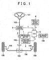
- FIG 1 is a block diagram schematically showing the structure of an electric power steering system according to an example embodiment of the invention, together with the structure of a vehicle related to the electric power steering system.
- the electric power steering system shown in FIG. 1 is a column assist type electric power steering system that includes a brushless motor 1, a reduction gear 2, a torque sensor 3, a vehicle speed sensor 4, a position detecting sensor 5, and an ECU (Electronic Control Unit; hereinafter referred to as "ECU”) 10.
- ECU Electronic Control Unit
- a steering wheel 101 is fixed to one end of a steering shaft 102.
- the other end of the steering shaft 102 is linked to a rack shaft 104 via a rack-and-pinion mechanism 103.
- Each end of the rack shaft 104 is connected to a wheel 106 via a connecting member 105 consisting of a tie-rod and a knuckle arm.
- the electric power steering system provides steering assist described below to reduce the load on the driver.
- the torque sensor 3 detects steering torque T applied to the steering shaft 102 by an operation of the steering wheel 101.
- the vehicle speed sensor 4 detects the vehicle speed S.
- the position detecting sensor 5 detects the rotational position P of a rotor of the brushless motor 1.
- the position detecting sensor 5 is formed by a resolver, for example.
- the ECU 10 is powered by an on-board battery 100 and drives the brushless motor 1 based on the steering torque T, the vehicle speed S, and the rotational position P.
- the brushless motor 1 generates steering assist force when driven by the ECU 10.
- the reduction gear 2 is provided between the brushless motor 1 and the steering shaft 102.
- the steering assist force generated by the brushless motor 1 is used to rotate the steering shaft 102 via the reduction gear 2.
- the steering shaft 102 rotates by both the steering torque applied to the steering wheel 101 and the steering assist force generated by the brushless motor 1.
- the electric power steering system performs steering assist by applying steering assist force generated by the brushless motor 1 to the steering mechanism of the vehicle.
- the electric power steering system according to the example embodiment of the invention is characterized by the motor control apparatus that drives the brushless motor 1. Therefore, the motor control apparatus in the electric power steering system will hereinafter be described.
- FIG. 2 is a block diagram of the structure of the motor control apparatus according to the example embodiment of the invention.
- the motor control apparatus shown in FIG. 2 is formed by the ECU 10 and drives the brushless motor 1 which has three phase windings, i.e., a u-phase winding, a v-phase winding, and a w-phase winding, not shown.
- the ECU 10 includes a phase compensator 11, a microcomputer 20, a three-phase PWM (Pulse Width Modulation) modulator 12, and a motor drive circuit 13.
- PWM Pulse Width Modulation
- the ECU 10 receives a signal indicative of the steering torque T output from the torque sensor 3, a signal indicative of the vehicle speed S output from the vehicle speed sensor 4, and a signal indicative of the rotational position P output from the position detecting sensor 5.
- the phase compensator 11 performs phase compensation on the steering torque T.
- the microcomputer 20 obtains a voltage command value used to drive the brushless motor 1. The function of the microcomputer 20 will be described in detail later.
- the microcomputer 20 functions as a command current setting portion 21, a d-axis command current calculating portion 21a, an open loop control portion 22, a voltage limiting portion 24, a dq-axis / three-phase converting portion 25, a dq-axis current estimating portion 26, an inductance adjusting portion 27, an angle calculating portion 28, and an angular velocity calculating portion 29, by executing programs stored in memory, not shown, housed in the ECU 10.
- the angle calculating portion 28 obtains the rotation angle (i.e., the electrical angle) of the rotor of the brushless motor 1 (hereinafter referred to as "angle ⁇ ") based on the rotational position P detected by the position detecting sensor 5.
- the angular velocity calculating portion 29 obtains the angular velocity (i.e., the rotational velocity of the electrical angle) ⁇ of the rotor of the brushless motor 1 based on the angle ⁇ .
- the angle ⁇ is the angle created between the u-axis and the d-axis when the u-axis, the v-axis, and the w-axis are set for the brushless motor 1 and the d-axis and the q-axis are set for the rotor 6 of the brushless motor 1, as shown in FIG. 3 .
- the command current setting portion 21 obtains a q-axis component of the current to be supplied to the brushless motor 1 (hereinafter referred to as "q-axis current command value Iq*") based on the steering torque T after phase compensation (i.e., an output signal from the phase compensator 11) and the vehicle speed S, and outputs the obtained q-axis current command value Iq* to the open loop control portion 22 and the dq-axis current estimating portion 26, which will be described later.
- phase compensation i.e., an output signal from the phase compensator 11
- the command current setting portion 21 houses a table (hereinafter referred to as an "assist map") that stores the corresponding relationship between the steering torque T and the command current, with the vehicle speed S as a parameter, and obtains the q-axis current command value Iq* referencing this assist map.
- the command current setting portion 21 is able to obtain the q-axis current command value Iq* to be supplied to the brushless motor 1 in order to generate an appropriate amount of steering assist force corresponding to that steering torque T, using the assist map.
- the d-axis command current calculating portion 21a obtains a d-axis component of the current to be supplied to the brushless motor 1 (hereinafter referred to as "d-axis current command value Id*") based on the q-axis current command value Iq* provided by the command current setting portion 21 and the angular velocity ⁇ provided by the angular velocity calculating portion 29.
- the d-axis command current calculating portion 21a then outputs the obtained d-axis current command value Id* to the open loop control portion 22 and the dq-axis current estimating portion 26 which will be described later.
- the open loop control portion 22 obtains the d-axis component and the q-axis component of the voltage to be applied to the brushless motor 1 (hereinafter the value of the d-axis component will be referred to as the "d-axis voltage command value Vd" and the value of the q-axis component will be referred to as the "q-axis voltage command value Vq") based on the q-axis current command value Iq* obtained by the command current setting portion 21, the d-axis current command value Id* obtained by the d-axis command current setting portion 21a, and the angular velocity ⁇ obtained by the angular velocity calculating portion 29.
- Vd R + P ⁇ Ld ⁇ Id * - ⁇ ⁇ Lq ⁇ Iq *
- Vq R + P ⁇ Lq ⁇ Iq * + ⁇ ⁇ Ld ⁇ Id * + ⁇ ⁇ ⁇
- Vd is the d-axis voltage command value
- Vq is the q-axis voltage command value
- Id* is the d-axis current command value
- Iq* is the q-axis current command value
- ⁇ is the angular velocity of the rotor
- R is the circuit resistance including the armature winding resistance
- Ld is the self-inductance of the d-axis
- Lq is the self-inductance of the q-axis
- ⁇ is 3/2 times the maximum value of the number of u-, v-, and w-phase arma
- R, Ld, and Lq are handled as known parameters and are stored in a storage portion 23.
- the circuit resistance represented by R includes wiring resistance between the brushless motor 1 and the ECU 10, and the wiring resistance and the resistance of the motor drive circuit 13 within the ECU 10.
- the open loop control portion 22 functions as a voltage command value calculating portion.
- the voltage limiting portion 24 outputs the d-axis voltage command value Vd obtained by the open loop control portion 22 to the dq-axis / three-phase converting portion 25 as a d-axis voltage estimated value Vd', and outputs the q-axis voltage command value Vq obtained by the open loop control portion 22 to the dq-axis / three-phase converting portion 25 as a q-axis voltage estimated value Vq'.
- a table that includes data indicative of the corresponding relationship between i) the self-inductance Lq of the q-axis and ii) the q-axis current and the d-axis current as well as a table that includes data indicative of the corresponding relationship between i) the self-inductance Ld of the d-axis and ii) the d-axis current and the q-axis, are stored in advance in the storage portion 23.
- the data in the tables is obtained in advance through testing or simulation or the like.
- the format of the data is not limited to a table. For example, when obtaining the self-inductances Ld and Lq by substituting the d-axis current value and the q-axis current value into an equation, the data may be a coefficient of that equation or in another format.
- the dq-axis / three-phase converting portion 25 converts the d-axis voltage estimated value Vd' and the q-axis voltage estimated value Vq' obtained by the open loop control portion 22 to voltage command values on a three-phase alternating current coordinate axes. More specifically, the dq-axis /three-phase converting portion 25 obtains a u-phase voltage estimated value Vu', a v-phase voltage estimated value Vv', and a w-phase voltage estimated value Vw' using Expressions (3) to (5) below based on the d-axis voltage estimated value Vd' and the q-axis voltage estimated value Vq'.
- the angle ⁇ in Expressions (3) and (4) above is an electrical angle obtained by the angle calculating portion 28.
- the u-phase voltage estimated value Vu', the v-phase voltage estimated value Vv', and the w-phase voltage estimated value Vw' may also be collectively referred to as "phase voltage estimated values Vu', Vv', and Vw'").
- Drive currents of the three phases are supplied to the brushless motor 1 by controlling the conduction state of the MOS-FETs using the PWM signals.
- sinusoidal currents corresponding to the ⁇ -phase voltage estimated value Vu', the v-phase voltage estimated value Vv', and the w-phase voltage estimated value Vw' are supplied to the three-phase windings of the brushless motor 1, causing the rotor of the brushless motor 1 to rotate.
- torque corresponding to the current flowing through the brushless motor 1 is generated in a rotating shaft of the brushless motor 1. This generated torque is used for auxiliary steering.
- Vd Vd ⁇ 2
- Vq Vqe + Vq ⁇ 2
- Vqe Vq ⁇ 2 + Vd ⁇ 2 2
- Vqe, Vd1, and Vq1 are known so Vd2 and Vq2 are obtained from Expressions (11) to (14). Furthermore, when the ratio of the q-axis voltage component Vq1 of the vector V1 to the q-axis voltage component Vq2 of the vector V2, or the ratio of the d-axis voltage component Vd1 of the vector V1 to the d-axis voltage component Vd2 of the vector V2 is obtained, those relationships are as shown in Expression (15) below.
- the q-axis current estimated value Iq' can also be obtained according to Expression (17) below.
- Iq ⁇ Vd ⁇ 2 / Vd ⁇ 1 ⁇ Iq *
- the phase voltage correction value calculating portion 32 reads the resistance values corresponding to the phase current estimated values Iu', Iv', and Iw' from the storage portion 34, and obtains the voltage drops ⁇ Vu, ⁇ Vv, and ⁇ Vw (i.e., second estimation parameter values) of the phases based on the read resistance values and the phase current estimated values Iu', Iv', and Iw'.
- the adder 33 obtains phase voltage command values Vuc, Vvc, and Vwc that have been corrected for the voltage drop by adding the voltage drops ⁇ Vu, ⁇ Vv, and ⁇ Vw to the phase voltage command values Vu, Vv, and Vw of the three phases, respectively.
- the motor drive circuit 13 is controlled based on the phase voltage command values Vuc, Vvc, and Vwc after the correction, so fluctuation in the current supplied to the brushless motor 1 due to a voltage drop can be suppressed.
- the voltage correction value calculating portion 41 obtains the phase voltage correction values ⁇ Vd and ⁇ Vq for correcting the d-axis voltage command value Vd and the q-axis voltage command value Vq, based on i) the d-axis current estimated value Id' and the q-axis current estimated value Iq' obtained by the dq-axis current estimating portion 26 and ii) the data read from the storage portion 43, and outputs the obtained phase voltage correction values ⁇ Vd and ⁇ Vq to the adder 42.
Landscapes
- Engineering & Computer Science (AREA)
- Power Engineering (AREA)
- Control Of Motors That Do Not Use Commutators (AREA)
- Power Steering Mechanism (AREA)
- Control Of Ac Motors In General (AREA)
- Steering Control In Accordance With Driving Conditions (AREA)
Claims (14)
- Appareil de commande de moteur qui commande un moteur sans balais, même sans capteurs de courant, comportant :une partie de réglage de valeur de commande de courant (21, 21a) qui établit une valeur de commande de courant d'axe d et une valeur de commande de courant d'axe q qui sont indicatives de courants devant être délivrés au moteur sans balais ;une partie de calcul de valeur de commande de tension (22) qui calcule une valeur de commande de tension d'axe d et une valeur de commande de tension d'axe q qui sont indicatives des tensions devant être appliquées sur le moteur sans balais afin de délivrer le courant indiqué par la valeur de commande de courant d'axe d et la valeur de commande de courant d'axe q au moteur sans balais ; etune partie de détermination (24a) qui détermine si l'amplitude, d'un vecteur de tension de commande, dans lequel la valeur de commande de tension d'axe d est désignée comme une composante de tension d'axe d et la valeur de commande de tension d'axe q est désignée comme une composante de tension d'axe q, est plus grande qu'une valeur de tension prédéterminée ;caractérisé en ce qu'il comprend en outre :une partie d'ajustement de vecteur de tension (24) qui ajuste l'amplitude d'un vecteur de tension qui correspond à un courant d'axe q et qui forme le vecteur de tension de commande afin d'ajuster l'amplitude du vecteur de tension de commande qui est égale ou inférieure à la valeur de tension prédéterminée quand la partie de détermination détermine l'amplitude du vecteur de tension de commande comme étant plus grande que la valeur de vecteur de tension prédéterminée ; etune partie d'estimation de courant (26) qui estime une valeur estimée de courant d'axe q sur la base de i) un rapport de l'amplitude du vecteur de tension après ajustement sur l'amplitude du vecteur de tension avant ajustement, et ii) la valeur de commande de courant d'axe q.
- Appareil de commande de moteur selon la revendication 1, comportant en outre :une première partie de stockage (23) dans laquelle des premières données indicatives d'une relation correspondante entre une première valeur de paramètre et au moins une valeur de courant d'axe d ou une valeur de courant d'axe q sont stockées ; etune partie de calcul de valeur de paramètre (27) qui lit les premières données correspondant à la valeur estimée de courant d'axe q dans la première partie de stockage, et calcule une première valeur de paramètre estimée sur la base des premières données lues et de la valeur estimée de courant d'axe q,la partie de calcul de valeur de commande de tension calculant la valeur de commande de tension d'axe d et la valeur de commande de tension d'axe q en utilisant la première valeur de paramètre estimée calculée.
- Appareil de commande de moteur selon la revendication 1, comportant en outre :une partie de conversion de courant de phase (31) qui convertit la valeur estimée de courant d'axe q en une valeur estimée de courant de phase.
- Appareil de commande de moteur selon la revendication 3, comportant en outre :une partie d'entraînement de moteur (13) qui comprend deux éléments de commutation reliés en série pour chaque phase et commande le moteur sans balais ;une deuxième partie de stockage (34) dans laquelle des deuxièmes données indicatives d'une relation correspondante entre une deuxième valeur de paramètre pour chaque phase et au moins une de la valeur de courant d'axe d ou de la valeur de courant d'axe q est stockée ; etune partie de correction de tension de phase (32, 33) qui corrige une tension d'un noeud des deux éléments de commutation,la partie de correction de tension de phase lisant les deuxièmes données correspondant à la valeur estimée de courant de phase dans la deuxième partie de stockage, calculant une deuxième valeur de paramètre estimée sur la base des deuxièmes données lues et de la valeur estimée de courant de phase, et corrigeant la tension du noeud en utilisant la deuxième valeur de paramètre estimée.
- Appareil de commande de moteur selon la revendication 1 ou 2, comportant en outre :une partie de correction de tension de commande (41, 42) qui corrige au moins une de la valeur de commande de tension d'axe d ou de la valeur de commande de tension d'axe q sur la base de la valeur estimée de courant d'axe q.
- Appareil de commande de moteur selon l'une quelconque des revendications 1 à 5, dans lequel la valeur de tension prédéterminée est la valeur de tension d'une d'alimentation du moteur sans balais.
- Système de direction assistée électrique pourvu de l'appareil de commande de moteur selon l'une quelconque des revendications 1 à 6.
- Appareil de commande de moteur qui commande un moteur sans balais, même sans capteurs de courant, comportant :une première partie de réglage de valeur de commande de courant (21) qui établit une valeur de commande de courant d'axe q indicative d'un courant devant être délivré au moteur sans balais ;une partie de détection de valeur angulaire (29) qui détecte la vitesse angulaire d'un rotor du moteur sans balais ;une deuxième partie de réglage de valeur de commande de courant (21a) qui établit une valeur de commande de courant d'axe d indicative d'un courant d'axe d devant être délivré au moteur sans balais sur la base d'au moins la valeur de commande de courant d'axe q et de la vitesse angulaire ;une partie de calcul de valeur de commande de tension (22) qui calcule une valeur de commande de tension d'axe d et une valeur de commande de tension d'axe q qui sont indicatives des tensions devant être appliquées sur le moteur sans balais afin de délivrer le courant indiqué par la valeur de commande de courant d'axe d et la valeur de commande de courant d'axe q au moteur sans balais ;une partie de détermination (24a) qui détermine si l'amplitude d'un vecteur de tension de commande, dans lequel la valeur de commande de tension d'axe d est désignée comme une composante de tension d'axe d et valeur de commande de tension d'axe q est désignée comme une composante de tension d'axe q, est plus grande qu'une valeur de tension prédéterminée ;caractérisé en ce qu'il comporte en outre :une partie d'ajustement de vecteur de tension (24) qui ajuste l'amplitude d'un vecteur de tension qui correspond à un courant d'axe d et qui forme le vecteur de tension de commande afin d'ajuster l'amplitude du vecteur de tension de commande comme étant égale ou moins à la valeur de tension prédéterminée quand la partie de détermination détermine l'amplitude du vecteur de tension de commande comme étant plus grande que la valeur de vecteur de tension prédéterminée ; etune partie d'estimation de courant (26) qui estime une valeur estimée de courant d'axe d sur la base i) d'un rapport de l'amplitude du vecteur de tension après ajustement sur l'amplitude du vecteur de tension avant ajustement, et ii) de la valeur de commande de courant d'axe d.
- Appareil de commande de moteur selon la revendication 8, comportant en outre :une première partie de stockage (23) dans laquelle des premières données indicatives d'une relation correspondante entre une première valeur de paramètre et au moins une valeur de courant d'axe d ou une valeur de courant d'axe q sont stockées ; etune partie de calcul de valeur de paramètre (27) qui lit les premières données correspondant à la valeur estimée de courant d'axe q dans la première partie de stockage, et calcule une première valeur de paramètre estimée sur la base des premières données lues et de la valeur estimée de courant d'axe q,la partie de calcul de valeur de commande de tension calculant la valeur de commande de tension d'axe d et la valeur de commande de tension d'axe q en utilisant la première valeur de paramètre estimée calculée.
- Appareil de commande de moteur selon la revendication 8, comportant en outre :une partie de conversion de courant de phase (31) qui convertit la valeur estimée de courant d'axe d en une valeur estimée de courant de phase.
- Appareil de commande de moteur selon la revendication 10, comportant en outre :une partie d'entraînement de moteur qui comprend deux éléments de commutation reliés en série pour chaque phase et commande le moteur sans balais (13) ;une deuxième partie de stockage dans laquelle des deuxièmes données indicatives d'une relation correspondante entre une deuxième valeur de paramètre pour chaque phase et au moins une de la valeur de courant d'axe d ou de la valeur de courant d'axe q est stockée (34) ; etune partie de correction de tension de phase (32, 33) qui corrige une tension d'un noeud des deux éléments de commutation,la partie de correction de tension de phase lisant les deuxièmes données correspondant à la valeur estimée de courant de phase dans la deuxième partie de stockage, calculant une deuxième valeur de paramètre estimée sur la base des deuxièmes données lues et de la valeur estimée de courant de phase, et corrigeant la tension du noeud en utilisant la deuxième valeur de paramètre estimée.
- Appareil de commande de moteur selon la revendication 8 ou 9, comportant en outre :une partie de correction de tension de commande (41, 42) qui corrige au moins une de la valeur de commande de tension d'axe d ou de la valeur de commande de tension d'axe q sur la base de la valeur estimée de courant d'axe d.
- Appareil de commande de moteur selon l'une quelconque des revendications 8 à 12, dans lequel la valeur de tension prédéterminée est la valeur de tension d'une d'alimentation du moteur sans balais.
- Système de direction de courant électrique pourvu d'un appareil de commande de moteur selon l'une quelconque des revendications 8 à 13.
Applications Claiming Priority (1)
| Application Number | Priority Date | Filing Date | Title |
|---|---|---|---|
| JP2008104688A JP5453729B2 (ja) | 2008-04-14 | 2008-04-14 | モータ制御装置および電動パワーステアリング装置 |
Publications (2)
| Publication Number | Publication Date |
|---|---|
| EP2110941A1 EP2110941A1 (fr) | 2009-10-21 |
| EP2110941B1 true EP2110941B1 (fr) | 2012-05-30 |
Family
ID=40810872
Family Applications (1)
| Application Number | Title | Priority Date | Filing Date |
|---|---|---|---|
| EP09157862A Not-in-force EP2110941B1 (fr) | 2008-04-14 | 2009-04-14 | Appareil de commande de moteur et système de direction assistée électrique |
Country Status (3)
| Country | Link |
|---|---|
| US (1) | US8115429B2 (fr) |
| EP (1) | EP2110941B1 (fr) |
| JP (1) | JP5453729B2 (fr) |
Families Citing this family (23)
| Publication number | Priority date | Publication date | Assignee | Title |
|---|---|---|---|---|
| DE112010000768T5 (de) * | 2009-01-28 | 2012-11-08 | Mitsubishi Electric Corporation | Ventilsteuervorr!chtung |
| JP2011041343A (ja) * | 2009-08-06 | 2011-02-24 | Toshiba Corp | モータ駆動装置及びモータ駆動方法 |
| JP2011135641A (ja) * | 2009-12-22 | 2011-07-07 | Denso Corp | モータ制御装置 |
| JP5314643B2 (ja) * | 2010-07-16 | 2013-10-16 | 國立台北科技大學 | 三相交流誘導モーター駆動器の制御システム |
| US8831854B2 (en) * | 2010-08-16 | 2014-09-09 | Chrysler Group Llc | Active shimmy mitigation |
| JP5703998B2 (ja) * | 2010-09-06 | 2015-04-22 | 株式会社ジェイテクト | 電動パワーステアリング装置 |
| JP5626702B2 (ja) * | 2010-11-10 | 2014-11-19 | 日本精工株式会社 | 電動パワーステアリング装置 |
| US8450962B2 (en) * | 2011-02-28 | 2013-05-28 | Deere & Company | System for controlling a motor |
| JP5923365B2 (ja) * | 2012-03-30 | 2016-05-24 | 本田技研工業株式会社 | 電動機の出力制御装置 |
| JP5590076B2 (ja) * | 2012-07-04 | 2014-09-17 | 株式会社デンソー | 多相回転機の制御装置 |
| JP6003924B2 (ja) * | 2014-02-25 | 2016-10-05 | 株式会社安川電機 | 回転電機制御装置、回転電機の制御方法 |
| WO2016178262A1 (fr) * | 2015-05-01 | 2016-11-10 | 三菱電機株式会社 | Dispositif de commande de direction assistée électrique et procédé de commande de direction assistée électrique |
| JP6396869B2 (ja) * | 2015-09-09 | 2018-09-26 | 日立オートモティブシステムズ株式会社 | モータ制御装置 |
| CN109716641B (zh) * | 2016-09-14 | 2021-05-04 | 国立大学法人横滨国立大学 | 电力供给系统 |
| JP6774622B2 (ja) * | 2016-09-26 | 2020-10-28 | 株式会社ジェイテクト | モータ制御装置 |
| EP3651339B1 (fr) * | 2017-07-04 | 2022-09-14 | Mitsubishi Electric Corporation | Dispositif onduleur et dispositif de direction assistée électrique |
| JP6990118B2 (ja) * | 2018-01-31 | 2022-01-12 | オークマ株式会社 | 電動機の制御装置 |
| KR102040706B1 (ko) | 2018-03-27 | 2019-11-05 | 현대모비스 주식회사 | 전동식 조향장치 및 그 제어방법 |
| CN111416560B (zh) * | 2020-04-27 | 2024-04-05 | 廖铉泓 | 一种无电流传感器的永磁同步电机控制方法及系统 |
| US12612100B2 (en) * | 2022-02-09 | 2026-04-28 | Mitsubishi Electric Corporation | Electric power steering device |
| JP7783777B2 (ja) * | 2022-04-25 | 2025-12-10 | Astemo株式会社 | 同期機制御装置、同期機制御方法、および電気車 |
| CN115833671A (zh) * | 2022-09-28 | 2023-03-21 | 江苏大学 | 一种双三相电机高精度模型预测电流控制系统及控制方法 |
| JP7819614B2 (ja) * | 2022-11-15 | 2026-02-25 | 株式会社豊田自動織機 | 電動機 |
Family Cites Families (16)
| Publication number | Priority date | Publication date | Assignee | Title |
|---|---|---|---|---|
| JP3455017B2 (ja) | 1996-06-24 | 2003-10-06 | 財団法人鉄道総合技術研究所 | 車両駆動用永久磁石同期電動機の制御装置 |
| JPH10257789A (ja) * | 1997-03-14 | 1998-09-25 | Mitsubishi Heavy Ind Ltd | モータ制御装置 |
| JP3714843B2 (ja) * | 2000-03-21 | 2005-11-09 | 光洋精工株式会社 | 電動パワーステアリング装置および電動ポンプ式パワーステアリング装置 |
| JP4221906B2 (ja) | 2001-02-09 | 2009-02-12 | 日本精工株式会社 | 電動パワーステアリング装置の制御装置 |
| JP2002272196A (ja) * | 2001-03-13 | 2002-09-20 | Toyo Electric Mfg Co Ltd | 同期電動機の制御装置 |
| JP2004229487A (ja) * | 2002-11-29 | 2004-08-12 | Toyoda Mach Works Ltd | モータ制御装置及びモータ制御方法 |
| JP2004208364A (ja) * | 2002-12-24 | 2004-07-22 | Yaskawa Electric Corp | 同期電動機の電流センサレス制御方法および制御装置 |
| JP3789895B2 (ja) * | 2003-02-28 | 2006-06-28 | 三菱電機株式会社 | 巻線界磁型同期モータの制御装置および巻線界磁型同期モータの回転位置ずれ補正方法 |
| JP4379702B2 (ja) * | 2004-02-10 | 2009-12-09 | 株式会社デンソー | ブラシレスモータ制御装置 |
| JP4371844B2 (ja) | 2004-02-16 | 2009-11-25 | 株式会社デンソー | ブラシレスモータ駆動装置 |
| JP2006014431A (ja) * | 2004-06-23 | 2006-01-12 | Yaskawa Electric Corp | 電動機の電流センサレス制御装置および制御方法 |
| JP2006014474A (ja) | 2004-06-25 | 2006-01-12 | Favess Co Ltd | モータ制御装置および電動パワーステアリング装置 |
| JP4581508B2 (ja) * | 2004-06-25 | 2010-11-17 | 富士電機システムズ株式会社 | 電圧形インバータの制御装置 |
| KR100645809B1 (ko) | 2004-12-20 | 2006-11-23 | 엘지전자 주식회사 | 영구자석형 모터의 약계자 운전을 위한 진각 제어장치 및그 방법 |
| JP5131432B2 (ja) * | 2007-02-08 | 2013-01-30 | 株式会社ジェイテクト | モータ用制御装置 |
| JP4961292B2 (ja) * | 2007-07-27 | 2012-06-27 | 三洋電機株式会社 | モータ制御装置 |
-
2008
- 2008-04-14 JP JP2008104688A patent/JP5453729B2/ja not_active Expired - Fee Related
-
2009
- 2009-04-14 US US12/423,393 patent/US8115429B2/en not_active Expired - Fee Related
- 2009-04-14 EP EP09157862A patent/EP2110941B1/fr not_active Not-in-force
Also Published As
| Publication number | Publication date |
|---|---|
| US20090256503A1 (en) | 2009-10-15 |
| US8115429B2 (en) | 2012-02-14 |
| JP5453729B2 (ja) | 2014-03-26 |
| JP2009261066A (ja) | 2009-11-05 |
| EP2110941A1 (fr) | 2009-10-21 |
Similar Documents
| Publication | Publication Date | Title |
|---|---|---|
| EP2110941B1 (fr) | Appareil de commande de moteur et système de direction assistée électrique | |
| EP2293428B1 (fr) | Dispositif de commande de moteur et dispositif de direction assistée électrique | |
| JP5365701B2 (ja) | 電動パワーステアリング装置 | |
| US8710775B2 (en) | Electric power steering apparatus | |
| US8541965B2 (en) | Motor controller and electronic power steering apparatus | |
| EP1961643B1 (fr) | Contrôleur de moteur et appareil de direction assistée électrique | |
| JP5263090B2 (ja) | 電動パワーステアリング装置 | |
| US9124211B2 (en) | Rotary electric machine control apparatus | |
| US8504242B2 (en) | Motor controller and electronic power steering apparatus | |
| JP2011194914A (ja) | 電動パワーステアリング装置およびこれに用いられる電動機駆動制御装置 | |
| JP5406226B2 (ja) | 電動パワーステアリング装置 | |
| EP2066018A2 (fr) | Dispositif de commande de moteur | |
| JP2011131643A (ja) | 電動パワーステアリング装置 | |
| JP5719177B2 (ja) | 電動パワーステアリング装置 | |
| JP5257374B2 (ja) | 電動パワーステアリング装置 | |
| JP2010029027A (ja) | モータ制御装置 | |
| JP2019050684A (ja) | パワーステアリング装置の制御装置 | |
| JP2011230531A (ja) | モータ制御装置 | |
| JP5444697B2 (ja) | モータ制御装置および電動パワーステアリング装置 | |
| JP2011131726A (ja) | 電動パワーステアリング装置 | |
| US10577014B2 (en) | Steering control apparatus |
Legal Events
| Date | Code | Title | Description |
|---|---|---|---|
| PUAI | Public reference made under article 153(3) epc to a published international application that has entered the european phase |
Free format text: ORIGINAL CODE: 0009012 |
|
| AK | Designated contracting states |
Kind code of ref document: A1 Designated state(s): AT BE BG CH CY CZ DE DK EE ES FI FR GB GR HR HU IE IS IT LI LT LU LV MC MK MT NL NO PL PT RO SE SI SK TR |
|
| 17P | Request for examination filed |
Effective date: 20100421 |
|
| GRAP | Despatch of communication of intention to grant a patent |
Free format text: ORIGINAL CODE: EPIDOSNIGR1 |
|
| GRAS | Grant fee paid |
Free format text: ORIGINAL CODE: EPIDOSNIGR3 |
|
| RIN1 | Information on inventor provided before grant (corrected) |
Inventor name: NAGASE, SHIGEKI Inventor name: YOSHIDA, KOUYA Inventor name: UEDA, TAKESHI |
|
| RAP1 | Party data changed (applicant data changed or rights of an application transferred) |
Owner name: JTEKT CORPORATION |
|
| GRAA | (expected) grant |
Free format text: ORIGINAL CODE: 0009210 |
|
| AK | Designated contracting states |
Kind code of ref document: B1 Designated state(s): AT BE BG CH CY CZ DE DK EE ES FI FR GB GR HR HU IE IS IT LI LT LU LV MC MK MT NL NO PL PT RO SE SI SK TR |
|
| REG | Reference to a national code |
Ref country code: GB Ref legal event code: FG4D |
|
| REG | Reference to a national code |
Ref country code: CH Ref legal event code: EP |
|
| REG | Reference to a national code |
Ref country code: AT Ref legal event code: REF Ref document number: 560454 Country of ref document: AT Kind code of ref document: T Effective date: 20120615 |
|
| REG | Reference to a national code |
Ref country code: IE Ref legal event code: FG4D |
|
| REG | Reference to a national code |
Ref country code: DE Ref legal event code: R096 Ref document number: 602009007275 Country of ref document: DE Effective date: 20120726 |
|
| REG | Reference to a national code |
Ref country code: NL Ref legal event code: VDEP Effective date: 20120530 |
|
| REG | Reference to a national code |
Ref country code: LT Ref legal event code: MG4D Effective date: 20120530 |
|
| PG25 | Lapsed in a contracting state [announced via postgrant information from national office to epo] |
Ref country code: CY Free format text: LAPSE BECAUSE OF FAILURE TO SUBMIT A TRANSLATION OF THE DESCRIPTION OR TO PAY THE FEE WITHIN THE PRESCRIBED TIME-LIMIT Effective date: 20120530 Ref country code: NO Free format text: LAPSE BECAUSE OF FAILURE TO SUBMIT A TRANSLATION OF THE DESCRIPTION OR TO PAY THE FEE WITHIN THE PRESCRIBED TIME-LIMIT Effective date: 20120830 Ref country code: FI Free format text: LAPSE BECAUSE OF FAILURE TO SUBMIT A TRANSLATION OF THE DESCRIPTION OR TO PAY THE FEE WITHIN THE PRESCRIBED TIME-LIMIT Effective date: 20120530 Ref country code: LT Free format text: LAPSE BECAUSE OF FAILURE TO SUBMIT A TRANSLATION OF THE DESCRIPTION OR TO PAY THE FEE WITHIN THE PRESCRIBED TIME-LIMIT Effective date: 20120530 Ref country code: IS Free format text: LAPSE BECAUSE OF FAILURE TO SUBMIT A TRANSLATION OF THE DESCRIPTION OR TO PAY THE FEE WITHIN THE PRESCRIBED TIME-LIMIT Effective date: 20120930 Ref country code: SE Free format text: LAPSE BECAUSE OF FAILURE TO SUBMIT A TRANSLATION OF THE DESCRIPTION OR TO PAY THE FEE WITHIN THE PRESCRIBED TIME-LIMIT Effective date: 20120530 |
|
| REG | Reference to a national code |
Ref country code: AT Ref legal event code: MK05 Ref document number: 560454 Country of ref document: AT Kind code of ref document: T Effective date: 20120530 |
|
| PG25 | Lapsed in a contracting state [announced via postgrant information from national office to epo] |
Ref country code: SI Free format text: LAPSE BECAUSE OF FAILURE TO SUBMIT A TRANSLATION OF THE DESCRIPTION OR TO PAY THE FEE WITHIN THE PRESCRIBED TIME-LIMIT Effective date: 20120530 Ref country code: LV Free format text: LAPSE BECAUSE OF FAILURE TO SUBMIT A TRANSLATION OF THE DESCRIPTION OR TO PAY THE FEE WITHIN THE PRESCRIBED TIME-LIMIT Effective date: 20120530 Ref country code: GR Free format text: LAPSE BECAUSE OF FAILURE TO SUBMIT A TRANSLATION OF THE DESCRIPTION OR TO PAY THE FEE WITHIN THE PRESCRIBED TIME-LIMIT Effective date: 20120831 Ref country code: HR Free format text: LAPSE BECAUSE OF FAILURE TO SUBMIT A TRANSLATION OF THE DESCRIPTION OR TO PAY THE FEE WITHIN THE PRESCRIBED TIME-LIMIT Effective date: 20120530 |
|
| PG25 | Lapsed in a contracting state [announced via postgrant information from national office to epo] |
Ref country code: BE Free format text: LAPSE BECAUSE OF FAILURE TO SUBMIT A TRANSLATION OF THE DESCRIPTION OR TO PAY THE FEE WITHIN THE PRESCRIBED TIME-LIMIT Effective date: 20120530 |
|
| PG25 | Lapsed in a contracting state [announced via postgrant information from national office to epo] |
Ref country code: CZ Free format text: LAPSE BECAUSE OF FAILURE TO SUBMIT A TRANSLATION OF THE DESCRIPTION OR TO PAY THE FEE WITHIN THE PRESCRIBED TIME-LIMIT Effective date: 20120530 Ref country code: NL Free format text: LAPSE BECAUSE OF FAILURE TO SUBMIT A TRANSLATION OF THE DESCRIPTION OR TO PAY THE FEE WITHIN THE PRESCRIBED TIME-LIMIT Effective date: 20120530 Ref country code: DK Free format text: LAPSE BECAUSE OF FAILURE TO SUBMIT A TRANSLATION OF THE DESCRIPTION OR TO PAY THE FEE WITHIN THE PRESCRIBED TIME-LIMIT Effective date: 20120530 Ref country code: AT Free format text: LAPSE BECAUSE OF FAILURE TO SUBMIT A TRANSLATION OF THE DESCRIPTION OR TO PAY THE FEE WITHIN THE PRESCRIBED TIME-LIMIT Effective date: 20120530 Ref country code: EE Free format text: LAPSE BECAUSE OF FAILURE TO SUBMIT A TRANSLATION OF THE DESCRIPTION OR TO PAY THE FEE WITHIN THE PRESCRIBED TIME-LIMIT Effective date: 20120530 Ref country code: SK Free format text: LAPSE BECAUSE OF FAILURE TO SUBMIT A TRANSLATION OF THE DESCRIPTION OR TO PAY THE FEE WITHIN THE PRESCRIBED TIME-LIMIT Effective date: 20120530 Ref country code: RO Free format text: LAPSE BECAUSE OF FAILURE TO SUBMIT A TRANSLATION OF THE DESCRIPTION OR TO PAY THE FEE WITHIN THE PRESCRIBED TIME-LIMIT Effective date: 20120530 |
|
| PG25 | Lapsed in a contracting state [announced via postgrant information from national office to epo] |
Ref country code: PT Free format text: LAPSE BECAUSE OF FAILURE TO SUBMIT A TRANSLATION OF THE DESCRIPTION OR TO PAY THE FEE WITHIN THE PRESCRIBED TIME-LIMIT Effective date: 20121001 Ref country code: PL Free format text: LAPSE BECAUSE OF FAILURE TO SUBMIT A TRANSLATION OF THE DESCRIPTION OR TO PAY THE FEE WITHIN THE PRESCRIBED TIME-LIMIT Effective date: 20120530 Ref country code: IT Free format text: LAPSE BECAUSE OF FAILURE TO SUBMIT A TRANSLATION OF THE DESCRIPTION OR TO PAY THE FEE WITHIN THE PRESCRIBED TIME-LIMIT Effective date: 20120530 |
|
| PLBE | No opposition filed within time limit |
Free format text: ORIGINAL CODE: 0009261 |
|
| STAA | Information on the status of an ep patent application or granted ep patent |
Free format text: STATUS: NO OPPOSITION FILED WITHIN TIME LIMIT |
|
| PG25 | Lapsed in a contracting state [announced via postgrant information from national office to epo] |
Ref country code: ES Free format text: LAPSE BECAUSE OF FAILURE TO SUBMIT A TRANSLATION OF THE DESCRIPTION OR TO PAY THE FEE WITHIN THE PRESCRIBED TIME-LIMIT Effective date: 20120910 |
|
| 26N | No opposition filed |
Effective date: 20130301 |
|
| REG | Reference to a national code |
Ref country code: DE Ref legal event code: R097 Ref document number: 602009007275 Country of ref document: DE Effective date: 20130301 |
|
| PG25 | Lapsed in a contracting state [announced via postgrant information from national office to epo] |
Ref country code: BG Free format text: LAPSE BECAUSE OF FAILURE TO SUBMIT A TRANSLATION OF THE DESCRIPTION OR TO PAY THE FEE WITHIN THE PRESCRIBED TIME-LIMIT Effective date: 20120830 |
|
| PG25 | Lapsed in a contracting state [announced via postgrant information from national office to epo] |
Ref country code: MC Free format text: LAPSE BECAUSE OF FAILURE TO SUBMIT A TRANSLATION OF THE DESCRIPTION OR TO PAY THE FEE WITHIN THE PRESCRIBED TIME-LIMIT Effective date: 20120530 |
|
| REG | Reference to a national code |
Ref country code: CH Ref legal event code: PL |
|
| GBPC | Gb: european patent ceased through non-payment of renewal fee |
Effective date: 20130414 |
|
| REG | Reference to a national code |
Ref country code: IE Ref legal event code: MM4A |
|
| PG25 | Lapsed in a contracting state [announced via postgrant information from national office to epo] |
Ref country code: LI Free format text: LAPSE BECAUSE OF NON-PAYMENT OF DUE FEES Effective date: 20130430 Ref country code: CH Free format text: LAPSE BECAUSE OF NON-PAYMENT OF DUE FEES Effective date: 20130430 Ref country code: GB Free format text: LAPSE BECAUSE OF NON-PAYMENT OF DUE FEES Effective date: 20130414 |
|
| PG25 | Lapsed in a contracting state [announced via postgrant information from national office to epo] |
Ref country code: IE Free format text: LAPSE BECAUSE OF NON-PAYMENT OF DUE FEES Effective date: 20130414 |
|
| PG25 | Lapsed in a contracting state [announced via postgrant information from national office to epo] |
Ref country code: MT Free format text: LAPSE BECAUSE OF FAILURE TO SUBMIT A TRANSLATION OF THE DESCRIPTION OR TO PAY THE FEE WITHIN THE PRESCRIBED TIME-LIMIT Effective date: 20120530 |
|
| PG25 | Lapsed in a contracting state [announced via postgrant information from national office to epo] |
Ref country code: TR Free format text: LAPSE BECAUSE OF FAILURE TO SUBMIT A TRANSLATION OF THE DESCRIPTION OR TO PAY THE FEE WITHIN THE PRESCRIBED TIME-LIMIT Effective date: 20120530 |
|
| PG25 | Lapsed in a contracting state [announced via postgrant information from national office to epo] |
Ref country code: HU Free format text: LAPSE BECAUSE OF FAILURE TO SUBMIT A TRANSLATION OF THE DESCRIPTION OR TO PAY THE FEE WITHIN THE PRESCRIBED TIME-LIMIT; INVALID AB INITIO Effective date: 20090414 Ref country code: LU Free format text: LAPSE BECAUSE OF NON-PAYMENT OF DUE FEES Effective date: 20130414 Ref country code: MK Free format text: LAPSE BECAUSE OF FAILURE TO SUBMIT A TRANSLATION OF THE DESCRIPTION OR TO PAY THE FEE WITHIN THE PRESCRIBED TIME-LIMIT Effective date: 20120530 |
|
| REG | Reference to a national code |
Ref country code: FR Ref legal event code: PLFP Year of fee payment: 8 |
|
| REG | Reference to a national code |
Ref country code: FR Ref legal event code: PLFP Year of fee payment: 9 |
|
| REG | Reference to a national code |
Ref country code: FR Ref legal event code: PLFP Year of fee payment: 10 |
|
| PGFP | Annual fee paid to national office [announced via postgrant information from national office to epo] |
Ref country code: FR Payment date: 20190313 Year of fee payment: 11 |
|
| PGFP | Annual fee paid to national office [announced via postgrant information from national office to epo] |
Ref country code: DE Payment date: 20190402 Year of fee payment: 11 |
|
| REG | Reference to a national code |
Ref country code: DE Ref legal event code: R119 Ref document number: 602009007275 Country of ref document: DE |
|
| PG25 | Lapsed in a contracting state [announced via postgrant information from national office to epo] |
Ref country code: FR Free format text: LAPSE BECAUSE OF NON-PAYMENT OF DUE FEES Effective date: 20200430 Ref country code: DE Free format text: LAPSE BECAUSE OF NON-PAYMENT OF DUE FEES Effective date: 20201103 |