EP2110944A2 - Generierungssystem - Google Patents
Generierungssystem Download PDFInfo
- Publication number
- EP2110944A2 EP2110944A2 EP09250706A EP09250706A EP2110944A2 EP 2110944 A2 EP2110944 A2 EP 2110944A2 EP 09250706 A EP09250706 A EP 09250706A EP 09250706 A EP09250706 A EP 09250706A EP 2110944 A2 EP2110944 A2 EP 2110944A2
- Authority
- EP
- European Patent Office
- Prior art keywords
- electrical
- generator
- load
- voltage
- electrical current
- Prior art date
- Legal status (The legal status is an assumption and is not a legal conclusion. Google has not performed a legal analysis and makes no representation as to the accuracy of the status listed.)
- Granted
Links
- 238000000034 method Methods 0.000 claims description 13
- 238000004891 communication Methods 0.000 claims description 5
- 230000001419 dependent effect Effects 0.000 claims description 4
- 239000002131 composite material Substances 0.000 claims description 3
- 230000008859 change Effects 0.000 claims description 2
- 230000001105 regulatory effect Effects 0.000 claims description 2
- 238000012423 maintenance Methods 0.000 abstract description 4
- 230000004043 responsiveness Effects 0.000 abstract 1
- 230000001052 transient effect Effects 0.000 abstract 1
- 230000004044 response Effects 0.000 description 4
- 230000001172 regenerating effect Effects 0.000 description 3
- 230000009471 action Effects 0.000 description 2
- 238000013459 approach Methods 0.000 description 2
- 230000001276 controlling effect Effects 0.000 description 2
- 238000010248 power generation Methods 0.000 description 2
- 239000013589 supplement Substances 0.000 description 2
- 230000004075 alteration Effects 0.000 description 1
- 230000008901 benefit Effects 0.000 description 1
- 230000008878 coupling Effects 0.000 description 1
- 238000010168 coupling process Methods 0.000 description 1
- 238000005859 coupling reaction Methods 0.000 description 1
- 230000003111 delayed effect Effects 0.000 description 1
- 230000000694 effects Effects 0.000 description 1
- 230000005611 electricity Effects 0.000 description 1
- 230000006872 improvement Effects 0.000 description 1
- 230000001939 inductive effect Effects 0.000 description 1
- 230000004048 modification Effects 0.000 description 1
- 238000012986 modification Methods 0.000 description 1
- 230000008569 process Effects 0.000 description 1
- 230000009467 reduction Effects 0.000 description 1
Images


Classifications
-
- H—ELECTRICITY
- H02—GENERATION; CONVERSION OR DISTRIBUTION OF ELECTRIC POWER
- H02P—CONTROL OR REGULATION OF ELECTRIC MOTORS, ELECTRIC GENERATORS OR DYNAMO-ELECTRIC CONVERTERS; CONTROLLING TRANSFORMERS, REACTORS OR CHOKE COILS
- H02P9/00—Arrangements for controlling electric generators for the purpose of obtaining a desired output
- H02P9/10—Control effected upon generator excitation circuit to reduce harmful effects of overloads or transients, e.g. sudden application of load, sudden removal of load, sudden change of load
- H02P9/102—Control effected upon generator excitation circuit to reduce harmful effects of overloads or transients, e.g. sudden application of load, sudden removal of load, sudden change of load for limiting effects of transients
-
- H—ELECTRICITY
- H02—GENERATION; CONVERSION OR DISTRIBUTION OF ELECTRIC POWER
- H02P—CONTROL OR REGULATION OF ELECTRIC MOTORS, ELECTRIC GENERATORS OR DYNAMO-ELECTRIC CONVERTERS; CONTROLLING TRANSFORMERS, REACTORS OR CHOKE COILS
- H02P2101/00—Special adaptation of control arrangements for generators
- H02P2101/30—Special adaptation of control arrangements for generators for aircraft
Definitions
- the present invention relates to generating systems and more particularly to generating systems comprising a number of electrical generators with one generator provided with voltage regulation and another generator provided with electrical current controllers.
- Generating systems which comprise a number of generators arranged to contribute to a common distribution arrangement.
- generators can be embedded within modern aero-engines in order to generate electricity for local engine control loads and also to meet electrical demand on an aircraft associated with the engine.
- parallel coupling in operation of the respective generators can bring benefits with regard to system efficiency, weight and availability of electrical power.
- a suitable control methodology is required. This methodology will avoid conflicts between the respective generation capacities and inputs from the generators.
- one of the generators operates with a voltage control with the others operating with electrical current control.
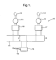
- Prior Art A typical prior system is illustrated in the attached drawing marked Prior Art.
- Voltage control and electrical current control are normally independent controls. Both controls may be implemented on the same generator but they will not be active at the same time.
- a generator operating under voltage control is responsible for controlling electrical system dynamics whereas a generator operating under electrical current control does not provide any dynamic support to the generator that is controlling the generator system voltage.
- an electrical generator or generators under electrical current control will at least attempt to maintain its electrical current output at the demand level at all times.
- the electrical current demand is normally provided from a higher level of system control which monitors, or predicts the total load level in the system and then decides the current demand for each generator under current control. Based upon this principle, the electrical current demand is relatively slow changing and hence, the electrical current control has a relatively slow response time. In such circumstances it is not possible for full system dynamics to be fulfilled with traditional electrical current control regimes. Electrical generators under electrical current demand controls will not respond to any system dynamics. Nevertheless, with regard to some electrical distribution systems relatively heavy electrical loads will result in highly dynamic scenarios with regard to the electrical power generation system. For example within an aeroplane there may be regenerative electrical surface actuators.
- voltage controlled generators will normally operate within stability margins up to a limit of load changes that can be managed before unacceptable voltage dynamics occur.
- the dynamics imposed can be too fast and too severe for the voltage controlled generator to maintain the system voltage within acceptable levels. In such circumstances unacceptable system operation is provided.
- a method of operating an electrical power system comprising a first electrical generator, a voltage controller, a second electrical generator, a current controller and a common electrical distribution arrangement, the first electrical generator and the second electrical generator being coupled to the common electrical distribution arrangement, the method comprising regulating electrical voltage upon the common electrical distribution arrangement using the first electrical generator and the voltage controller, providing electrical current using the second electrical generator and the current controller, providing and actuator signal to the current controller to alter the electrical current provided by the second generator, the actuator signal providing an indication of status of an electrical load upon the common electrical distribution arrangement.
- an electrical power system comprising a first electrical generator, a voltage controller, a second electrical generator, a current controller and a common electrical distribution arrangement, the first electrical generator and the second electrical generator being coupled to the common electrical distribution arrangement, the first electrical generator being controlled by the voltage controller and being arranged to configure the first electrical generator to regulate voltage upon the common electrical distribution arrangement, the second electrical generator being controlled by the current controller and being arranged to provide electrical current to the common electrical distribution arrangement, the system having an electrical load coupled to the common electrical distribution arrangement, a control element arranged to provide an actuator signal to the current controller upon change in the status of the electrical load and the current controller being arrangement to alter the electrical current provided by the second electrical generator dependent upon the actuator signal.
- the actuator signal comprises a composite signal from a plurality of electrical loads.
- the actuator signal is provided by hard wiring or network communication with the current controller.
- the electrical load provides or receives electrical current from the common electrical distribution arrangement.
- the electrical load includes a resistive component and/or a reactive component.
- the electrical load is variable.
- the electrical power system may be incorporated in a gas turbine engine and/or in an aircraft.
- the electrical current controlled generator 12 is associated with the arrangement 15 through an electrical current controller 17. In such circumstances the controller 17 will be arranged to configure the generator 12 for generating its proportion of the electrical current to the arrangement 15.
- the electrical distribution arrangement 15 is associated with a load 18.
- the load 18 may be an actuator or a control load for one of the generators 11, 12 or one of the prime mover engines 13, 14. If the load 18 is significant or the number of loads 18 switched is significant on the arrangement 15 then there will be a dip or raise in the operational voltage. If these changes are within the capabilities of the generator 11 and associated controller 16 then the generator 11 will be used so that the operational voltage is dynamically adjusted for maintenance of the voltage within acceptable margins for operation of the arrangement. If the load 18 or a combination of loads 18 is greater than the capabilities of the generator 11 and the controller 16, then instability will be created.
- a demand signal or actuator signal 19 for the load 18 is also coupled to the electrical current controller 17.
- the controller 17 will effectively have instantaneous or possibly in view of lag within the arrangement 15 slightly prior notice with regard to electrical current demand.
- the controller 17 can then appropriately configure a generator 12 in order to provide electrical current for the expected load 18. With the electrical current adjusted by the controller 17 in view of the provision of the actuator signal associated with load 18 it will be understood that de-stabilising transients as a result of switching of the load 18, which may not be within the capability of the generator 11 alone, can be more easily accommodated.
- the electrical load 18 and/or its demand signal 19 provides an indication of the status of the electrical load to the arrangement.
- Fig 2 provides a schematic illustration of an electrical current control arrangement in accordance with aspects of the present invention.
- a steady state electrical current command Icmd is provided to a control element or summation block 21.
- the summation block 21 also receives electrical current demand in the form as indicated above of an actuator signal ILd.
- the value of ILd may be zero or relatively low.
- the summation block 21 will identify such a zero or low load demand and provide no action.
- the voltage controlled generator and voltage controller will be adequate to accommodate for dynamic instabilities and therefore adequate to maintain the desired voltage level in the arrangement 15.
- the summation block 21 will identify a necessary electrical current target value, Itgt, to be presented to a comparator 22.
- This comparator 22 in a similar fashion to that described above with regard to comparator 4 in the Prior Art illustration will compare the electrical current output Iout from the generator 23 under appropriate electrical current control with the necessary electrical current demand, the current target value Itgt, for stability.
- the voltage controlled generator although generally designed and designated for expected operational transients, may struggle with certain load conditions.
- the actual current control generator can also be utilised dynamically to supplement the effectiveness of the voltage controlled generator and therefore provide greater stability with regard to operation of the generator system, or at least dampen such instability.
- Fig 3 provides a generator system model in accordance with aspects of the present invention.
- the system model depicted in Fig 3 provides two electrical power generators operating in parallel on a ring structured common distribution arrangement. It will be appreciated that in more practical systems more generators may be utilised.
- a first generator designated by broken line 31 is voltage controlled.
- a second generator designated by broken line 32 is controlled by electrical current. In such circumstances the first generator 31 maintains a desired electrical voltage value in a common distribution arrangement 33 whilst the second generator 32 supplies electrical current typically along with other second generators not shown.
- electrical resistance loads 34 are provided along with active or variable loads 35, 36.
- resistive loads and active loads which can be switched into and out of the distribution arrangement 33.
- the arrangement 33 itself incorporates a system load as a result of its structure.
- This system contains connection cables characterised by resistive and inductive elements, 37.
- the voltage controlled generator 31 will be adequate in order to substantially maintain a desired operational voltage for the distribution arrangement 33 with respect to the resistive loads 34.
- dynamic electrical current control is provided to the generator 32.
- the electrical current control generator 32 is configured to provide an electrical current load 38. In such circumstances within the electrical current control the generator will be configured to maintain that electrical current Icmd as described above and defined by input 38 in Fig 3 .
- the loads 35, 36 are arranged to provide a respective actuator signal 41, 42 to the electrical current controller and in particular a module 43, in order to adjust the electrical current output from the generator 32 to effectively meet the electrical current demands of the loads 35, 36.
- the module 43 as described above is a summation block like 21 which will determine the electrical current requirement and therefore configure the generator 32 in order to provide electrical current at the required level for the loads 35, 36 to the arrangement 33.
- the voltage control will reconfigure the generator 31 in terms of speed 43 and other parameters within the generator 31 in order to provide the voltage dynamic adjustment for maintenance of a desired electrical voltage in the arrangement 33.
- the electrical current controlled generator 32 again reconfiguration to meet the necessary electrical current for dynamic response to switching of the loads 35, 36 may be through adjustment of a speed 44 or other configuration of the generator 32.
- oscilloscopes 45, 46, 47, 48 are provided in order to identify voltage and electrical current levels within the system depicted in Fig 3 .
- Fig 4 provides a comparison between the same operating conditions both with and without electrical current dynamic or forward feed control in accordance with aspects of the present invention. It will be observed from the simulated results that when dynamic electrical current control, in accordance with aspects of the present invention, is not used, the dynamic current load will be supplied by the voltage control generator. Owing to delayed response of the load demand upon the voltage control generator, the system voltage will vary over an unacceptable range. When an almost instantaneous dynamic electrical current control is utilised, then the dynamic electrical current load is generally supplied largely by the generator under electrical current control and this relieves the burden from the voltage control generator resulting in a greater maintenance of a constant generator system voltage.
- Fig 4 the left hand oscilloscope traces illustrate respectively at (a) distribution arrangement system voltage, (b) current from the voltage control generator and (c) current from the electrical current controlled generator. Without dynamic electrical current control in accordance with aspects of the present invention and with such dynamic control with regard to the corresponding right hand oscilloscope traces. As can be seen during a load switching action greater stability is provided particularly with regard to system voltage ( Fig 4a ) with forward dynamic electrical current load control in response to actuator signals from the load to the electrical current control in accordance with aspects of the present invention.
- a generator system in which dynamic electrical current generation is achieved to support dynamic loads applied upon a distribution arrangement.
- switched dynamic loads have less effect upon and result in less instability with regard to system voltages within the distribution arrangement.
- aspects of the present invention operate a generator system by providing a link between the load or its demand and the electrical current controller for the electrical generator. It is this process of utilising the actuator signal for the dynamic load in terms of pre-empting or forward feeding to enhance electrical current output from the second generator which augments the effectiveness of voltage control of the principal stability providing first generator in accordance with aspects of the present invention. Forward feed improves the effectiveness of generally slower electrical current control of generators.
- electrical power systems will incorporate a number of generators.
- the voltage controlled generator as indicated will be designed to provide sufficient margin for stability with respect to certain and in particular resistive loads.
- utilisation of pre-emptive or forward feeding dynamic electrical current control to adjust the electrical current provided by the second generators utilising electrical current control will be advantageous is maintaining stability.
- the electrical current generators may increase or decrease the electrical current contribution by the respective second electrical generator dependent upon the load demand presented to the common distribution arrangement.
- the load may draw electrical current or inject electrical current dependent upon the phase of operation of the load.
- the actuator signal may be presented to all electrical current controllers for all second generators in accordance with aspects of the present invention or to particular notable current generators and their associated electrical current controls hardwired or otherwise in communication with respective loads in order to be particularly responsive to those loads and requirements.
Landscapes
- Engineering & Computer Science (AREA)
- Power Engineering (AREA)
- Control Of Eletrric Generators (AREA)
Applications Claiming Priority (1)
| Application Number | Priority Date | Filing Date | Title |
|---|---|---|---|
| GBGB0806492.5A GB0806492D0 (en) | 2008-04-10 | 2008-04-10 | A generating system |
Publications (3)
| Publication Number | Publication Date |
|---|---|
| EP2110944A2 true EP2110944A2 (de) | 2009-10-21 |
| EP2110944A3 EP2110944A3 (de) | 2017-08-09 |
| EP2110944B1 EP2110944B1 (de) | 2018-10-10 |
Family
ID=39433397
Family Applications (1)
| Application Number | Title | Priority Date | Filing Date |
|---|---|---|---|
| EP09250706.0A Not-in-force EP2110944B1 (de) | 2008-04-10 | 2009-03-12 | Generierungssystem |
Country Status (3)
| Country | Link |
|---|---|
| US (1) | US8154260B2 (de) |
| EP (1) | EP2110944B1 (de) |
| GB (1) | GB0806492D0 (de) |
Cited By (1)
| Publication number | Priority date | Publication date | Assignee | Title |
|---|---|---|---|---|
| EP2683049A3 (de) * | 2012-07-02 | 2016-05-11 | Kohler Co. | Generatorverwaltungssystem zur selektiven Trennung von Brennstoff an einen Generator zum Hinzufügen einer Last zu einem Bus |
Families Citing this family (1)
| Publication number | Priority date | Publication date | Assignee | Title |
|---|---|---|---|---|
| US10491147B2 (en) * | 2017-11-29 | 2019-11-26 | Ford Global Technologies, Llc | Dual alternator vehicle power management |
Family Cites Families (11)
| Publication number | Priority date | Publication date | Assignee | Title |
|---|---|---|---|---|
| US2707264A (en) * | 1952-09-13 | 1955-04-26 | Westinghouse Electric Corp | Generator control system |
| US4262209A (en) | 1979-02-26 | 1981-04-14 | Berner Charles A | Supplemental electrical power generating system |
| JPH0810999B2 (ja) | 1983-06-01 | 1996-01-31 | 本田技研工業株式会社 | 車両用発電機の制御装置 |
| US4829228A (en) | 1988-05-06 | 1989-05-09 | General Motors Corporation | Dual generator electrical system |
| US5216350A (en) * | 1991-06-10 | 1993-06-01 | Ford Motor Company | Method and system for controlling an alternator |
| US5594322A (en) * | 1993-05-12 | 1997-01-14 | Sundstrand Corporation | Starter/generator system with variable-frequency exciter control |
| US5977648A (en) * | 1996-10-21 | 1999-11-02 | Sundstrand Corporation | Hydraulically driven low reactance, large air gap permanent magnet generator and voltage regulation system for use therewith |
| US6281664B1 (en) * | 1999-01-13 | 2001-08-28 | Honda Giken Kogyo Kabushiki Kaisha | Generator and generator apparatus |
| US6943531B2 (en) * | 2002-03-20 | 2005-09-13 | Yamaha Hatsudoki Kabushiki Kaisha | Portable power supply incorporating a generator driven by an engine |
| US7309974B2 (en) * | 2005-11-08 | 2007-12-18 | Honeywell International, Inc. | System and method for AC power generation from a reluctance machine |
| GB2435529B (en) * | 2006-02-23 | 2008-06-18 | Rolls Royce Plc | A generator control arrangement |
-
2008
- 2008-04-10 GB GBGB0806492.5A patent/GB0806492D0/en not_active Ceased
-
2009
- 2009-03-12 EP EP09250706.0A patent/EP2110944B1/de not_active Not-in-force
- 2009-03-16 US US12/382,392 patent/US8154260B2/en active Active
Cited By (1)
| Publication number | Priority date | Publication date | Assignee | Title |
|---|---|---|---|---|
| EP2683049A3 (de) * | 2012-07-02 | 2016-05-11 | Kohler Co. | Generatorverwaltungssystem zur selektiven Trennung von Brennstoff an einen Generator zum Hinzufügen einer Last zu einem Bus |
Also Published As
| Publication number | Publication date |
|---|---|
| US20100033141A1 (en) | 2010-02-11 |
| EP2110944B1 (de) | 2018-10-10 |
| US8154260B2 (en) | 2012-04-10 |
| EP2110944A3 (de) | 2017-08-09 |
| GB0806492D0 (en) | 2008-05-14 |
Similar Documents
| Publication | Publication Date | Title |
|---|---|---|
| US10814999B2 (en) | Method and apparatus for operating a power distribution system | |
| EP3553908B1 (de) | Verfahren und vorrichtung zum betrieb eines stromverteilungssystems | |
| KR102627677B1 (ko) | 동적 하이브리드 제어 | |
| US10396565B2 (en) | System and method for power distribution | |
| CA2882057C (en) | Systems and methods for the control and operation of a parallel motor controller architecture | |
| US11437813B2 (en) | System controller for a hybrid aircraft propulsion system | |
| US11520362B2 (en) | Control for a target common bus voltage | |
| CN103158875B (zh) | 电力分配系统和方法 | |
| US7573243B2 (en) | Generator control arrangement | |
| CN100550572C (zh) | 稳定化电力供给系统及其运用方法、以及电力稳定供给的运用工序 | |
| CA2820130A1 (en) | Power distribution systems | |
| EP2110945B1 (de) | Verfahren und System zur Erzeugung elektrischen Stroms | |
| US12331725B2 (en) | Method and windfarm control stage for controlling a windfarm | |
| WO2016060839A1 (en) | Programmable inverter for controllable grid response | |
| US20220037889A1 (en) | Method for feeding in electrical power by means of a wind power installation | |
| US20160105030A1 (en) | Bus conditioner for an aircraft power system | |
| CN103425047B (zh) | 发电机组协调控制系统和方法 | |
| US8154260B2 (en) | Generating system | |
| CA3049617C (en) | Method for feeding electrical power into an electrical supply network | |
| US11518538B2 (en) | Control for a target common bus voltage | |
| Wunderlich et al. | Novel rate-limited droop control for DC distribution with impulsive loads | |
| JP6853225B2 (ja) | 発電設備の運転方法 | |
| CA3064028A1 (en) | Method for supplying electric power by means of a converter-controlled generator unit, in particular a wind turbine |
Legal Events
| Date | Code | Title | Description |
|---|---|---|---|
| PUAI | Public reference made under article 153(3) epc to a published international application that has entered the european phase |
Free format text: ORIGINAL CODE: 0009012 |
|
| AK | Designated contracting states |
Kind code of ref document: A2 Designated state(s): AT BE BG CH CY CZ DE DK EE ES FI FR GB GR HR HU IE IS IT LI LT LU LV MC MK MT NL NO PL PT RO SE SI SK TR |
|
| AX | Request for extension of the european patent |
Extension state: AL BA RS |
|
| RAP1 | Party data changed (applicant data changed or rights of an application transferred) |
Owner name: ROLLS-ROYCE PLC |
|
| PUAL | Search report despatched |
Free format text: ORIGINAL CODE: 0009013 |
|
| AK | Designated contracting states |
Kind code of ref document: A3 Designated state(s): AT BE BG CH CY CZ DE DK EE ES FI FR GB GR HR HU IE IS IT LI LT LU LV MC MK MT NL NO PL PT RO SE SI SK TR |
|
| AX | Request for extension of the european patent |
Extension state: AL BA RS |
|
| RIC1 | Information provided on ipc code assigned before grant |
Ipc: H02P 9/10 20060101AFI20170630BHEP |
|
| STAA | Information on the status of an ep patent application or granted ep patent |
Free format text: STATUS: REQUEST FOR EXAMINATION WAS MADE |
|
| 17P | Request for examination filed |
Effective date: 20180118 |
|
| RBV | Designated contracting states (corrected) |
Designated state(s): AT BE BG CH CY CZ DE DK EE ES FI FR GB GR HR HU IE IS IT LI LT LU LV MC MK MT NL NO PL PT RO SE SI SK TR |
|
| AKX | Designation fees paid |
Designated state(s): AT BE BG CH CY CZ DE DK EE ES FI FR GB GR HR HU IE IS IT LI LT LU LV MC MK MT NL NO PL PT RO SE SI SK TR |
|
| AXX | Extension fees paid |
Extension state: BA Extension state: RS Extension state: AL |
|
| GRAP | Despatch of communication of intention to grant a patent |
Free format text: ORIGINAL CODE: EPIDOSNIGR1 |
|
| STAA | Information on the status of an ep patent application or granted ep patent |
Free format text: STATUS: GRANT OF PATENT IS INTENDED |
|
| INTG | Intention to grant announced |
Effective date: 20180502 |
|
| GRAS | Grant fee paid |
Free format text: ORIGINAL CODE: EPIDOSNIGR3 |
|
| GRAA | (expected) grant |
Free format text: ORIGINAL CODE: 0009210 |
|
| STAA | Information on the status of an ep patent application or granted ep patent |
Free format text: STATUS: THE PATENT HAS BEEN GRANTED |
|
| AK | Designated contracting states |
Kind code of ref document: B1 Designated state(s): AT BE BG CH CY CZ DE DK EE ES FI FR GB GR HR HU IE IS IT LI LT LU LV MC MK MT NL NO PL PT RO SE SI SK TR |
|
| REG | Reference to a national code |
Ref country code: GB Ref legal event code: FG4D |
|
| REG | Reference to a national code |
Ref country code: CH Ref legal event code: EP Ref country code: AT Ref legal event code: REF Ref document number: 1052421 Country of ref document: AT Kind code of ref document: T Effective date: 20181015 |
|
| REG | Reference to a national code |
Ref country code: IE Ref legal event code: FG4D |
|
| REG | Reference to a national code |
Ref country code: DE Ref legal event code: R096 Ref document number: 602009054958 Country of ref document: DE |
|
| REG | Reference to a national code |
Ref country code: NL Ref legal event code: MP Effective date: 20181010 |
|
| REG | Reference to a national code |
Ref country code: LT Ref legal event code: MG4D |
|
| REG | Reference to a national code |
Ref country code: AT Ref legal event code: MK05 Ref document number: 1052421 Country of ref document: AT Kind code of ref document: T Effective date: 20181010 |
|
| PG25 | Lapsed in a contracting state [announced via postgrant information from national office to epo] |
Ref country code: NL Free format text: LAPSE BECAUSE OF FAILURE TO SUBMIT A TRANSLATION OF THE DESCRIPTION OR TO PAY THE FEE WITHIN THE PRESCRIBED TIME-LIMIT Effective date: 20181010 |
|
| PG25 | Lapsed in a contracting state [announced via postgrant information from national office to epo] |
Ref country code: IS Free format text: LAPSE BECAUSE OF FAILURE TO SUBMIT A TRANSLATION OF THE DESCRIPTION OR TO PAY THE FEE WITHIN THE PRESCRIBED TIME-LIMIT Effective date: 20190210 Ref country code: FI Free format text: LAPSE BECAUSE OF FAILURE TO SUBMIT A TRANSLATION OF THE DESCRIPTION OR TO PAY THE FEE WITHIN THE PRESCRIBED TIME-LIMIT Effective date: 20181010 Ref country code: BG Free format text: LAPSE BECAUSE OF FAILURE TO SUBMIT A TRANSLATION OF THE DESCRIPTION OR TO PAY THE FEE WITHIN THE PRESCRIBED TIME-LIMIT Effective date: 20190110 Ref country code: HR Free format text: LAPSE BECAUSE OF FAILURE TO SUBMIT A TRANSLATION OF THE DESCRIPTION OR TO PAY THE FEE WITHIN THE PRESCRIBED TIME-LIMIT Effective date: 20181010 Ref country code: PL Free format text: LAPSE BECAUSE OF FAILURE TO SUBMIT A TRANSLATION OF THE DESCRIPTION OR TO PAY THE FEE WITHIN THE PRESCRIBED TIME-LIMIT Effective date: 20181010 Ref country code: LV Free format text: LAPSE BECAUSE OF FAILURE TO SUBMIT A TRANSLATION OF THE DESCRIPTION OR TO PAY THE FEE WITHIN THE PRESCRIBED TIME-LIMIT Effective date: 20181010 Ref country code: ES Free format text: LAPSE BECAUSE OF FAILURE TO SUBMIT A TRANSLATION OF THE DESCRIPTION OR TO PAY THE FEE WITHIN THE PRESCRIBED TIME-LIMIT Effective date: 20181010 Ref country code: AT Free format text: LAPSE BECAUSE OF FAILURE TO SUBMIT A TRANSLATION OF THE DESCRIPTION OR TO PAY THE FEE WITHIN THE PRESCRIBED TIME-LIMIT Effective date: 20181010 Ref country code: LT Free format text: LAPSE BECAUSE OF FAILURE TO SUBMIT A TRANSLATION OF THE DESCRIPTION OR TO PAY THE FEE WITHIN THE PRESCRIBED TIME-LIMIT Effective date: 20181010 Ref country code: NO Free format text: LAPSE BECAUSE OF FAILURE TO SUBMIT A TRANSLATION OF THE DESCRIPTION OR TO PAY THE FEE WITHIN THE PRESCRIBED TIME-LIMIT Effective date: 20190110 |
|
| PGFP | Annual fee paid to national office [announced via postgrant information from national office to epo] |
Ref country code: FR Payment date: 20190325 Year of fee payment: 11 Ref country code: DE Payment date: 20190327 Year of fee payment: 11 |
|
| PG25 | Lapsed in a contracting state [announced via postgrant information from national office to epo] |
Ref country code: GR Free format text: LAPSE BECAUSE OF FAILURE TO SUBMIT A TRANSLATION OF THE DESCRIPTION OR TO PAY THE FEE WITHIN THE PRESCRIBED TIME-LIMIT Effective date: 20190111 Ref country code: PT Free format text: LAPSE BECAUSE OF FAILURE TO SUBMIT A TRANSLATION OF THE DESCRIPTION OR TO PAY THE FEE WITHIN THE PRESCRIBED TIME-LIMIT Effective date: 20190210 Ref country code: SE Free format text: LAPSE BECAUSE OF FAILURE TO SUBMIT A TRANSLATION OF THE DESCRIPTION OR TO PAY THE FEE WITHIN THE PRESCRIBED TIME-LIMIT Effective date: 20181010 |
|
| REG | Reference to a national code |
Ref country code: DE Ref legal event code: R097 Ref document number: 602009054958 Country of ref document: DE |
|
| PG25 | Lapsed in a contracting state [announced via postgrant information from national office to epo] |
Ref country code: IT Free format text: LAPSE BECAUSE OF FAILURE TO SUBMIT A TRANSLATION OF THE DESCRIPTION OR TO PAY THE FEE WITHIN THE PRESCRIBED TIME-LIMIT Effective date: 20181010 Ref country code: CZ Free format text: LAPSE BECAUSE OF FAILURE TO SUBMIT A TRANSLATION OF THE DESCRIPTION OR TO PAY THE FEE WITHIN THE PRESCRIBED TIME-LIMIT Effective date: 20181010 Ref country code: DK Free format text: LAPSE BECAUSE OF FAILURE TO SUBMIT A TRANSLATION OF THE DESCRIPTION OR TO PAY THE FEE WITHIN THE PRESCRIBED TIME-LIMIT Effective date: 20181010 |
|
| PLBE | No opposition filed within time limit |
Free format text: ORIGINAL CODE: 0009261 |
|
| STAA | Information on the status of an ep patent application or granted ep patent |
Free format text: STATUS: NO OPPOSITION FILED WITHIN TIME LIMIT |
|
| PG25 | Lapsed in a contracting state [announced via postgrant information from national office to epo] |
Ref country code: EE Free format text: LAPSE BECAUSE OF FAILURE TO SUBMIT A TRANSLATION OF THE DESCRIPTION OR TO PAY THE FEE WITHIN THE PRESCRIBED TIME-LIMIT Effective date: 20181010 Ref country code: SK Free format text: LAPSE BECAUSE OF FAILURE TO SUBMIT A TRANSLATION OF THE DESCRIPTION OR TO PAY THE FEE WITHIN THE PRESCRIBED TIME-LIMIT Effective date: 20181010 Ref country code: RO Free format text: LAPSE BECAUSE OF FAILURE TO SUBMIT A TRANSLATION OF THE DESCRIPTION OR TO PAY THE FEE WITHIN THE PRESCRIBED TIME-LIMIT Effective date: 20181010 |
|
| 26N | No opposition filed |
Effective date: 20190711 |
|
| PG25 | Lapsed in a contracting state [announced via postgrant information from national office to epo] |
Ref country code: MC Free format text: LAPSE BECAUSE OF FAILURE TO SUBMIT A TRANSLATION OF THE DESCRIPTION OR TO PAY THE FEE WITHIN THE PRESCRIBED TIME-LIMIT Effective date: 20181010 Ref country code: SI Free format text: LAPSE BECAUSE OF FAILURE TO SUBMIT A TRANSLATION OF THE DESCRIPTION OR TO PAY THE FEE WITHIN THE PRESCRIBED TIME-LIMIT Effective date: 20181010 |
|
| PGFP | Annual fee paid to national office [announced via postgrant information from national office to epo] |
Ref country code: GB Payment date: 20190404 Year of fee payment: 11 |
|
| REG | Reference to a national code |
Ref country code: CH Ref legal event code: PL |
|
| PG25 | Lapsed in a contracting state [announced via postgrant information from national office to epo] |
Ref country code: LU Free format text: LAPSE BECAUSE OF NON-PAYMENT OF DUE FEES Effective date: 20190312 |
|
| REG | Reference to a national code |
Ref country code: BE Ref legal event code: MM Effective date: 20190331 |
|
| PG25 | Lapsed in a contracting state [announced via postgrant information from national office to epo] |
Ref country code: CH Free format text: LAPSE BECAUSE OF NON-PAYMENT OF DUE FEES Effective date: 20190331 Ref country code: IE Free format text: LAPSE BECAUSE OF NON-PAYMENT OF DUE FEES Effective date: 20190312 Ref country code: LI Free format text: LAPSE BECAUSE OF NON-PAYMENT OF DUE FEES Effective date: 20190331 |
|
| PG25 | Lapsed in a contracting state [announced via postgrant information from national office to epo] |
Ref country code: BE Free format text: LAPSE BECAUSE OF NON-PAYMENT OF DUE FEES Effective date: 20190331 |
|
| PG25 | Lapsed in a contracting state [announced via postgrant information from national office to epo] |
Ref country code: TR Free format text: LAPSE BECAUSE OF FAILURE TO SUBMIT A TRANSLATION OF THE DESCRIPTION OR TO PAY THE FEE WITHIN THE PRESCRIBED TIME-LIMIT Effective date: 20181010 |
|
| PG25 | Lapsed in a contracting state [announced via postgrant information from national office to epo] |
Ref country code: MT Free format text: LAPSE BECAUSE OF NON-PAYMENT OF DUE FEES Effective date: 20190312 |
|
| REG | Reference to a national code |
Ref country code: DE Ref legal event code: R119 Ref document number: 602009054958 Country of ref document: DE |
|
| PG25 | Lapsed in a contracting state [announced via postgrant information from national office to epo] |
Ref country code: DE Free format text: LAPSE BECAUSE OF NON-PAYMENT OF DUE FEES Effective date: 20201001 Ref country code: FR Free format text: LAPSE BECAUSE OF NON-PAYMENT OF DUE FEES Effective date: 20200331 |
|
| GBPC | Gb: european patent ceased through non-payment of renewal fee |
Effective date: 20200312 |
|
| PG25 | Lapsed in a contracting state [announced via postgrant information from national office to epo] |
Ref country code: GB Free format text: LAPSE BECAUSE OF NON-PAYMENT OF DUE FEES Effective date: 20200312 |
|
| PG25 | Lapsed in a contracting state [announced via postgrant information from national office to epo] |
Ref country code: CY Free format text: LAPSE BECAUSE OF FAILURE TO SUBMIT A TRANSLATION OF THE DESCRIPTION OR TO PAY THE FEE WITHIN THE PRESCRIBED TIME-LIMIT Effective date: 20181010 |
|
| PG25 | Lapsed in a contracting state [announced via postgrant information from national office to epo] |
Ref country code: HU Free format text: LAPSE BECAUSE OF FAILURE TO SUBMIT A TRANSLATION OF THE DESCRIPTION OR TO PAY THE FEE WITHIN THE PRESCRIBED TIME-LIMIT; INVALID AB INITIO Effective date: 20090312 |
|
| PG25 | Lapsed in a contracting state [announced via postgrant information from national office to epo] |
Ref country code: MK Free format text: LAPSE BECAUSE OF FAILURE TO SUBMIT A TRANSLATION OF THE DESCRIPTION OR TO PAY THE FEE WITHIN THE PRESCRIBED TIME-LIMIT Effective date: 20181010 |