EP2111190B1 - Gestentete Herzklappenvorrichtungen für atrioventrikulären Klappenersatz - Google Patents
Gestentete Herzklappenvorrichtungen für atrioventrikulären Klappenersatz Download PDFInfo
- Publication number
- EP2111190B1 EP2111190B1 EP08724552.8A EP08724552A EP2111190B1 EP 2111190 B1 EP2111190 B1 EP 2111190B1 EP 08724552 A EP08724552 A EP 08724552A EP 2111190 B1 EP2111190 B1 EP 2111190B1
- Authority
- EP
- European Patent Office
- Prior art keywords
- stent
- barrel
- assembly
- barrels
- length
- Prior art date
- Legal status (The legal status is an assumption and is not a legal conclusion. Google has not performed a legal analysis and makes no representation as to the accuracy of the status listed.)
- Ceased
Links
- 0 *C1=CCCC1 Chemical compound *C1=CCCC1 0.000 description 1
Images


Classifications
-
- A—HUMAN NECESSITIES
- A61—MEDICAL OR VETERINARY SCIENCE; HYGIENE
- A61F—FILTERS IMPLANTABLE INTO BLOOD VESSELS; PROSTHESES; DEVICES PROVIDING PATENCY TO, OR PREVENTING COLLAPSING OF, TUBULAR STRUCTURES OF THE BODY, e.g. STENTS; ORTHOPAEDIC, NURSING OR CONTRACEPTIVE DEVICES; FOMENTATION; TREATMENT OR PROTECTION OF EYES OR EARS; BANDAGES, DRESSINGS OR ABSORBENT PADS; FIRST-AID KITS
- A61F2/00—Filters implantable into blood vessels; Prostheses, i.e. artificial substitutes or replacements for parts of the body; Appliances for connecting them with the body; Devices providing patency to, or preventing collapsing of, tubular structures of the body, e.g. stents
- A61F2/02—Prostheses implantable into the body
- A61F2/24—Heart valves ; Vascular valves, e.g. venous valves; Heart implants, e.g. passive devices for improving the function of the native valve or the heart muscle; Transmyocardial revascularisation [TMR] devices; Valves implantable in the body
- A61F2/2412—Heart valves ; Vascular valves, e.g. venous valves; Heart implants, e.g. passive devices for improving the function of the native valve or the heart muscle; Transmyocardial revascularisation [TMR] devices; Valves implantable in the body with soft flexible valve members, e.g. tissue valves shaped like natural valves
- A61F2/2418—Scaffolds therefor, e.g. support stents
-
- A—HUMAN NECESSITIES
- A61—MEDICAL OR VETERINARY SCIENCE; HYGIENE
- A61F—FILTERS IMPLANTABLE INTO BLOOD VESSELS; PROSTHESES; DEVICES PROVIDING PATENCY TO, OR PREVENTING COLLAPSING OF, TUBULAR STRUCTURES OF THE BODY, e.g. STENTS; ORTHOPAEDIC, NURSING OR CONTRACEPTIVE DEVICES; FOMENTATION; TREATMENT OR PROTECTION OF EYES OR EARS; BANDAGES, DRESSINGS OR ABSORBENT PADS; FIRST-AID KITS
- A61F2/00—Filters implantable into blood vessels; Prostheses, i.e. artificial substitutes or replacements for parts of the body; Appliances for connecting them with the body; Devices providing patency to, or preventing collapsing of, tubular structures of the body, e.g. stents
- A61F2/02—Prostheses implantable into the body
- A61F2/24—Heart valves ; Vascular valves, e.g. venous valves; Heart implants, e.g. passive devices for improving the function of the native valve or the heart muscle; Transmyocardial revascularisation [TMR] devices; Valves implantable in the body
- A61F2/2427—Devices for manipulating or deploying heart valves during implantation
- A61F2/243—Deployment by mechanical expansion
- A61F2/2433—Deployment by mechanical expansion using balloon catheter
-
- A—HUMAN NECESSITIES
- A61—MEDICAL OR VETERINARY SCIENCE; HYGIENE
- A61F—FILTERS IMPLANTABLE INTO BLOOD VESSELS; PROSTHESES; DEVICES PROVIDING PATENCY TO, OR PREVENTING COLLAPSING OF, TUBULAR STRUCTURES OF THE BODY, e.g. STENTS; ORTHOPAEDIC, NURSING OR CONTRACEPTIVE DEVICES; FOMENTATION; TREATMENT OR PROTECTION OF EYES OR EARS; BANDAGES, DRESSINGS OR ABSORBENT PADS; FIRST-AID KITS
- A61F2/00—Filters implantable into blood vessels; Prostheses, i.e. artificial substitutes or replacements for parts of the body; Appliances for connecting them with the body; Devices providing patency to, or preventing collapsing of, tubular structures of the body, e.g. stents
- A61F2/82—Devices providing patency to, or preventing collapsing of, tubular structures of the body, e.g. stents
-
- A—HUMAN NECESSITIES
- A61—MEDICAL OR VETERINARY SCIENCE; HYGIENE
- A61F—FILTERS IMPLANTABLE INTO BLOOD VESSELS; PROSTHESES; DEVICES PROVIDING PATENCY TO, OR PREVENTING COLLAPSING OF, TUBULAR STRUCTURES OF THE BODY, e.g. STENTS; ORTHOPAEDIC, NURSING OR CONTRACEPTIVE DEVICES; FOMENTATION; TREATMENT OR PROTECTION OF EYES OR EARS; BANDAGES, DRESSINGS OR ABSORBENT PADS; FIRST-AID KITS
- A61F2/00—Filters implantable into blood vessels; Prostheses, i.e. artificial substitutes or replacements for parts of the body; Appliances for connecting them with the body; Devices providing patency to, or preventing collapsing of, tubular structures of the body, e.g. stents
- A61F2/95—Instruments specially adapted for placement or removal of stents or stent-grafts
- A61F2/958—Inflatable balloons for placing stents or stent-grafts
-
- A—HUMAN NECESSITIES
- A61—MEDICAL OR VETERINARY SCIENCE; HYGIENE
- A61F—FILTERS IMPLANTABLE INTO BLOOD VESSELS; PROSTHESES; DEVICES PROVIDING PATENCY TO, OR PREVENTING COLLAPSING OF, TUBULAR STRUCTURES OF THE BODY, e.g. STENTS; ORTHOPAEDIC, NURSING OR CONTRACEPTIVE DEVICES; FOMENTATION; TREATMENT OR PROTECTION OF EYES OR EARS; BANDAGES, DRESSINGS OR ABSORBENT PADS; FIRST-AID KITS
- A61F2/00—Filters implantable into blood vessels; Prostheses, i.e. artificial substitutes or replacements for parts of the body; Appliances for connecting them with the body; Devices providing patency to, or preventing collapsing of, tubular structures of the body, e.g. stents
- A61F2/82—Devices providing patency to, or preventing collapsing of, tubular structures of the body, e.g. stents
- A61F2/852—Two or more distinct overlapping stents
-
- A—HUMAN NECESSITIES
- A61—MEDICAL OR VETERINARY SCIENCE; HYGIENE
- A61F—FILTERS IMPLANTABLE INTO BLOOD VESSELS; PROSTHESES; DEVICES PROVIDING PATENCY TO, OR PREVENTING COLLAPSING OF, TUBULAR STRUCTURES OF THE BODY, e.g. STENTS; ORTHOPAEDIC, NURSING OR CONTRACEPTIVE DEVICES; FOMENTATION; TREATMENT OR PROTECTION OF EYES OR EARS; BANDAGES, DRESSINGS OR ABSORBENT PADS; FIRST-AID KITS
- A61F2/00—Filters implantable into blood vessels; Prostheses, i.e. artificial substitutes or replacements for parts of the body; Appliances for connecting them with the body; Devices providing patency to, or preventing collapsing of, tubular structures of the body, e.g. stents
- A61F2/02—Prostheses implantable into the body
- A61F2/04—Hollow or tubular parts of organs, e.g. bladders, tracheae, bronchi or bile ducts
- A61F2/06—Blood vessels
- A61F2002/065—Y-shaped blood vessels
-
- A—HUMAN NECESSITIES
- A61—MEDICAL OR VETERINARY SCIENCE; HYGIENE
- A61F—FILTERS IMPLANTABLE INTO BLOOD VESSELS; PROSTHESES; DEVICES PROVIDING PATENCY TO, OR PREVENTING COLLAPSING OF, TUBULAR STRUCTURES OF THE BODY, e.g. STENTS; ORTHOPAEDIC, NURSING OR CONTRACEPTIVE DEVICES; FOMENTATION; TREATMENT OR PROTECTION OF EYES OR EARS; BANDAGES, DRESSINGS OR ABSORBENT PADS; FIRST-AID KITS
- A61F2/00—Filters implantable into blood vessels; Prostheses, i.e. artificial substitutes or replacements for parts of the body; Appliances for connecting them with the body; Devices providing patency to, or preventing collapsing of, tubular structures of the body, e.g. stents
- A61F2/82—Devices providing patency to, or preventing collapsing of, tubular structures of the body, e.g. stents
- A61F2/848—Devices providing patency to, or preventing collapsing of, tubular structures of the body, e.g. stents having means for fixation to the vessel wall, e.g. barbs
- A61F2002/8486—Devices providing patency to, or preventing collapsing of, tubular structures of the body, e.g. stents having means for fixation to the vessel wall, e.g. barbs provided on at least one of the ends
-
- A—HUMAN NECESSITIES
- A61—MEDICAL OR VETERINARY SCIENCE; HYGIENE
- A61F—FILTERS IMPLANTABLE INTO BLOOD VESSELS; PROSTHESES; DEVICES PROVIDING PATENCY TO, OR PREVENTING COLLAPSING OF, TUBULAR STRUCTURES OF THE BODY, e.g. STENTS; ORTHOPAEDIC, NURSING OR CONTRACEPTIVE DEVICES; FOMENTATION; TREATMENT OR PROTECTION OF EYES OR EARS; BANDAGES, DRESSINGS OR ABSORBENT PADS; FIRST-AID KITS
- A61F2210/00—Particular material properties of prostheses classified in groups A61F2/00 - A61F2/26 or A61F2/82 or A61F9/00 or A61F11/00 or subgroups thereof
- A61F2210/0014—Particular material properties of prostheses classified in groups A61F2/00 - A61F2/26 or A61F2/82 or A61F9/00 or A61F11/00 or subgroups thereof using shape memory or superelastic materials, e.g. nitinol
-
- A—HUMAN NECESSITIES
- A61—MEDICAL OR VETERINARY SCIENCE; HYGIENE
- A61F—FILTERS IMPLANTABLE INTO BLOOD VESSELS; PROSTHESES; DEVICES PROVIDING PATENCY TO, OR PREVENTING COLLAPSING OF, TUBULAR STRUCTURES OF THE BODY, e.g. STENTS; ORTHOPAEDIC, NURSING OR CONTRACEPTIVE DEVICES; FOMENTATION; TREATMENT OR PROTECTION OF EYES OR EARS; BANDAGES, DRESSINGS OR ABSORBENT PADS; FIRST-AID KITS
- A61F2220/00—Fixations or connections for prostheses classified in groups A61F2/00 - A61F2/26 or A61F2/82 or A61F9/00 or A61F11/00 or subgroups thereof
- A61F2220/0008—Fixation appliances for connecting prostheses to the body
- A61F2220/0016—Fixation appliances for connecting prostheses to the body with sharp anchoring protrusions, e.g. barbs, pins, spikes
-
- A—HUMAN NECESSITIES
- A61—MEDICAL OR VETERINARY SCIENCE; HYGIENE
- A61F—FILTERS IMPLANTABLE INTO BLOOD VESSELS; PROSTHESES; DEVICES PROVIDING PATENCY TO, OR PREVENTING COLLAPSING OF, TUBULAR STRUCTURES OF THE BODY, e.g. STENTS; ORTHOPAEDIC, NURSING OR CONTRACEPTIVE DEVICES; FOMENTATION; TREATMENT OR PROTECTION OF EYES OR EARS; BANDAGES, DRESSINGS OR ABSORBENT PADS; FIRST-AID KITS
- A61F2230/00—Geometry of prostheses classified in groups A61F2/00 - A61F2/26 or A61F2/82 or A61F9/00 or A61F11/00 or subgroups thereof
- A61F2230/0002—Two-dimensional shapes, e.g. cross-sections
- A61F2230/0004—Rounded shapes, e.g. with rounded corners
- A61F2230/0008—Rounded shapes, e.g. with rounded corners elliptical or oval
-
- A—HUMAN NECESSITIES
- A61—MEDICAL OR VETERINARY SCIENCE; HYGIENE
- A61F—FILTERS IMPLANTABLE INTO BLOOD VESSELS; PROSTHESES; DEVICES PROVIDING PATENCY TO, OR PREVENTING COLLAPSING OF, TUBULAR STRUCTURES OF THE BODY, e.g. STENTS; ORTHOPAEDIC, NURSING OR CONTRACEPTIVE DEVICES; FOMENTATION; TREATMENT OR PROTECTION OF EYES OR EARS; BANDAGES, DRESSINGS OR ABSORBENT PADS; FIRST-AID KITS
- A61F2230/00—Geometry of prostheses classified in groups A61F2/00 - A61F2/26 or A61F2/82 or A61F9/00 or A61F11/00 or subgroups thereof
- A61F2230/0002—Two-dimensional shapes, e.g. cross-sections
- A61F2230/0004—Rounded shapes, e.g. with rounded corners
- A61F2230/001—Figure-8-shaped, e.g. hourglass-shaped
-
- A—HUMAN NECESSITIES
- A61—MEDICAL OR VETERINARY SCIENCE; HYGIENE
- A61F—FILTERS IMPLANTABLE INTO BLOOD VESSELS; PROSTHESES; DEVICES PROVIDING PATENCY TO, OR PREVENTING COLLAPSING OF, TUBULAR STRUCTURES OF THE BODY, e.g. STENTS; ORTHOPAEDIC, NURSING OR CONTRACEPTIVE DEVICES; FOMENTATION; TREATMENT OR PROTECTION OF EYES OR EARS; BANDAGES, DRESSINGS OR ABSORBENT PADS; FIRST-AID KITS
- A61F2230/00—Geometry of prostheses classified in groups A61F2/00 - A61F2/26 or A61F2/82 or A61F9/00 or A61F11/00 or subgroups thereof
- A61F2230/0002—Two-dimensional shapes, e.g. cross-sections
- A61F2230/0017—Angular shapes
-
- A—HUMAN NECESSITIES
- A61—MEDICAL OR VETERINARY SCIENCE; HYGIENE
- A61F—FILTERS IMPLANTABLE INTO BLOOD VESSELS; PROSTHESES; DEVICES PROVIDING PATENCY TO, OR PREVENTING COLLAPSING OF, TUBULAR STRUCTURES OF THE BODY, e.g. STENTS; ORTHOPAEDIC, NURSING OR CONTRACEPTIVE DEVICES; FOMENTATION; TREATMENT OR PROTECTION OF EYES OR EARS; BANDAGES, DRESSINGS OR ABSORBENT PADS; FIRST-AID KITS
- A61F2230/00—Geometry of prostheses classified in groups A61F2/00 - A61F2/26 or A61F2/82 or A61F9/00 or A61F11/00 or subgroups thereof
- A61F2230/0002—Two-dimensional shapes, e.g. cross-sections
- A61F2230/0028—Shapes in the form of latin or greek characters
- A61F2230/005—Rosette-shaped, e.g. star-shaped
-
- A—HUMAN NECESSITIES
- A61—MEDICAL OR VETERINARY SCIENCE; HYGIENE
- A61F—FILTERS IMPLANTABLE INTO BLOOD VESSELS; PROSTHESES; DEVICES PROVIDING PATENCY TO, OR PREVENTING COLLAPSING OF, TUBULAR STRUCTURES OF THE BODY, e.g. STENTS; ORTHOPAEDIC, NURSING OR CONTRACEPTIVE DEVICES; FOMENTATION; TREATMENT OR PROTECTION OF EYES OR EARS; BANDAGES, DRESSINGS OR ABSORBENT PADS; FIRST-AID KITS
- A61F2230/00—Geometry of prostheses classified in groups A61F2/00 - A61F2/26 or A61F2/82 or A61F9/00 or A61F11/00 or subgroups thereof
- A61F2230/0002—Two-dimensional shapes, e.g. cross-sections
- A61F2230/0028—Shapes in the form of latin or greek characters
- A61F2230/0054—V-shaped
-
- A—HUMAN NECESSITIES
- A61—MEDICAL OR VETERINARY SCIENCE; HYGIENE
- A61F—FILTERS IMPLANTABLE INTO BLOOD VESSELS; PROSTHESES; DEVICES PROVIDING PATENCY TO, OR PREVENTING COLLAPSING OF, TUBULAR STRUCTURES OF THE BODY, e.g. STENTS; ORTHOPAEDIC, NURSING OR CONTRACEPTIVE DEVICES; FOMENTATION; TREATMENT OR PROTECTION OF EYES OR EARS; BANDAGES, DRESSINGS OR ABSORBENT PADS; FIRST-AID KITS
- A61F2250/00—Special features of prostheses classified in groups A61F2/00 - A61F2/26 or A61F2/82 or A61F9/00 or A61F11/00 or subgroups thereof
- A61F2250/0014—Special features of prostheses classified in groups A61F2/00 - A61F2/26 or A61F2/82 or A61F9/00 or A61F11/00 or subgroups thereof having different values of a given property or geometrical feature, e.g. mechanical property or material property, at different locations within the same prosthesis
- A61F2250/0018—Special features of prostheses classified in groups A61F2/00 - A61F2/26 or A61F2/82 or A61F9/00 or A61F11/00 or subgroups thereof having different values of a given property or geometrical feature, e.g. mechanical property or material property, at different locations within the same prosthesis differing in elasticity, stiffness or compressibility
-
- A—HUMAN NECESSITIES
- A61—MEDICAL OR VETERINARY SCIENCE; HYGIENE
- A61F—FILTERS IMPLANTABLE INTO BLOOD VESSELS; PROSTHESES; DEVICES PROVIDING PATENCY TO, OR PREVENTING COLLAPSING OF, TUBULAR STRUCTURES OF THE BODY, e.g. STENTS; ORTHOPAEDIC, NURSING OR CONTRACEPTIVE DEVICES; FOMENTATION; TREATMENT OR PROTECTION OF EYES OR EARS; BANDAGES, DRESSINGS OR ABSORBENT PADS; FIRST-AID KITS
- A61F2250/00—Special features of prostheses classified in groups A61F2/00 - A61F2/26 or A61F2/82 or A61F9/00 or A61F11/00 or subgroups thereof
- A61F2250/0014—Special features of prostheses classified in groups A61F2/00 - A61F2/26 or A61F2/82 or A61F9/00 or A61F11/00 or subgroups thereof having different values of a given property or geometrical feature, e.g. mechanical property or material property, at different locations within the same prosthesis
- A61F2250/0036—Special features of prostheses classified in groups A61F2/00 - A61F2/26 or A61F2/82 or A61F9/00 or A61F11/00 or subgroups thereof having different values of a given property or geometrical feature, e.g. mechanical property or material property, at different locations within the same prosthesis differing in thickness
-
- A—HUMAN NECESSITIES
- A61—MEDICAL OR VETERINARY SCIENCE; HYGIENE
- A61F—FILTERS IMPLANTABLE INTO BLOOD VESSELS; PROSTHESES; DEVICES PROVIDING PATENCY TO, OR PREVENTING COLLAPSING OF, TUBULAR STRUCTURES OF THE BODY, e.g. STENTS; ORTHOPAEDIC, NURSING OR CONTRACEPTIVE DEVICES; FOMENTATION; TREATMENT OR PROTECTION OF EYES OR EARS; BANDAGES, DRESSINGS OR ABSORBENT PADS; FIRST-AID KITS
- A61F2250/00—Special features of prostheses classified in groups A61F2/00 - A61F2/26 or A61F2/82 or A61F9/00 or A61F11/00 or subgroups thereof
- A61F2250/0014—Special features of prostheses classified in groups A61F2/00 - A61F2/26 or A61F2/82 or A61F9/00 or A61F11/00 or subgroups thereof having different values of a given property or geometrical feature, e.g. mechanical property or material property, at different locations within the same prosthesis
- A61F2250/0037—Special features of prostheses classified in groups A61F2/00 - A61F2/26 or A61F2/82 or A61F9/00 or A61F11/00 or subgroups thereof having different values of a given property or geometrical feature, e.g. mechanical property or material property, at different locations within the same prosthesis differing in height or in length
-
- A—HUMAN NECESSITIES
- A61—MEDICAL OR VETERINARY SCIENCE; HYGIENE
- A61F—FILTERS IMPLANTABLE INTO BLOOD VESSELS; PROSTHESES; DEVICES PROVIDING PATENCY TO, OR PREVENTING COLLAPSING OF, TUBULAR STRUCTURES OF THE BODY, e.g. STENTS; ORTHOPAEDIC, NURSING OR CONTRACEPTIVE DEVICES; FOMENTATION; TREATMENT OR PROTECTION OF EYES OR EARS; BANDAGES, DRESSINGS OR ABSORBENT PADS; FIRST-AID KITS
- A61F2250/00—Special features of prostheses classified in groups A61F2/00 - A61F2/26 or A61F2/82 or A61F9/00 or A61F11/00 or subgroups thereof
- A61F2250/0014—Special features of prostheses classified in groups A61F2/00 - A61F2/26 or A61F2/82 or A61F9/00 or A61F11/00 or subgroups thereof having different values of a given property or geometrical feature, e.g. mechanical property or material property, at different locations within the same prosthesis
- A61F2250/0039—Special features of prostheses classified in groups A61F2/00 - A61F2/26 or A61F2/82 or A61F9/00 or A61F11/00 or subgroups thereof having different values of a given property or geometrical feature, e.g. mechanical property or material property, at different locations within the same prosthesis differing in diameter
-
- A—HUMAN NECESSITIES
- A61—MEDICAL OR VETERINARY SCIENCE; HYGIENE
- A61F—FILTERS IMPLANTABLE INTO BLOOD VESSELS; PROSTHESES; DEVICES PROVIDING PATENCY TO, OR PREVENTING COLLAPSING OF, TUBULAR STRUCTURES OF THE BODY, e.g. STENTS; ORTHOPAEDIC, NURSING OR CONTRACEPTIVE DEVICES; FOMENTATION; TREATMENT OR PROTECTION OF EYES OR EARS; BANDAGES, DRESSINGS OR ABSORBENT PADS; FIRST-AID KITS
- A61F2250/00—Special features of prostheses classified in groups A61F2/00 - A61F2/26 or A61F2/82 or A61F9/00 or A61F11/00 or subgroups thereof
- A61F2250/0058—Additional features; Implant or prostheses properties not otherwise provided for
- A61F2250/006—Additional features; Implant or prostheses properties not otherwise provided for modular
- A61F2250/0064—Sets comprising a plurality of prosthetic parts of different sizes
-
- A—HUMAN NECESSITIES
- A61—MEDICAL OR VETERINARY SCIENCE; HYGIENE
- A61F—FILTERS IMPLANTABLE INTO BLOOD VESSELS; PROSTHESES; DEVICES PROVIDING PATENCY TO, OR PREVENTING COLLAPSING OF, TUBULAR STRUCTURES OF THE BODY, e.g. STENTS; ORTHOPAEDIC, NURSING OR CONTRACEPTIVE DEVICES; FOMENTATION; TREATMENT OR PROTECTION OF EYES OR EARS; BANDAGES, DRESSINGS OR ABSORBENT PADS; FIRST-AID KITS
- A61F2250/00—Special features of prostheses classified in groups A61F2/00 - A61F2/26 or A61F2/82 or A61F9/00 or A61F11/00 or subgroups thereof
- A61F2250/0058—Additional features; Implant or prostheses properties not otherwise provided for
- A61F2250/0069—Sealing means
Definitions
- the present invention relates generally to devices and methods for repair of heart valves, and more particularly to prosthetic heart valves for use in replacement of the mitral valve.
- the mitral valve which is located on the left side of the heart and which forms or defines a valve annulus and valve leaflets.
- the mitral valve is located between the left atrium and the left ventricle, and serves to direct oxygenated blood from the lungs through the left side of the heart and into the aorta for distribution to the body.
- the mitral valve is a passive structure in that it does not itself expend any energy and does not perform any active contractile function.
- the mitral valve includes two moveable leaflets that open and close in response to differential pressures on either side of the valve. Ideally, the leaflets move apart from each other when the valve is in an open position, and meet or "coapt" when the valve is in a closed position.
- problems can develop with valves, which can generally be classified as either stenosis, in which a valve does not open properly, or insufficiency (also called regurgitation), in which a valve does not close properly. Stenosis and insufficiency may occur concomitantly in the same valve.
- the effects of valvular dysfunction vary, with mitral regurgitation or backflow typically having relatively severe physiological consequences to the patient.
- Regurgitation along with other abnormalities of the mitral valve, can increase the workload placed on the heart.
- medication can be sufficient to treat the patient, which is the preferred option when it is viable; however, in many cases, defective valves have to be repaired or completely replaced in order for the patient to live a normal life.
- valve repair is sometimes either impossible or undesirable or has failed, such as in cases where dilation of the valve annulus is not the problem, leaving valve replacement as the preferred option for improving operation of the mitral valve.
- the two general categories of valves that are available for implantation are mechanical valves and bioprosthetic or tissue valves.
- Mechanical valves have been used for many years and encompass a wide variety of designs that accommodate the blood flow requirements of the particular location where they will be implanted. Although the materials and design features of these valves are continuously being improved, they do increase the risk of clotting in the blood stream, which can lead to a heart attack or stroke. Thus, mechanical valve recipients must take anti-coagulant drugs for life to prevent the potential of blood clots.
- tissue valves can sometimes suffer from structural problems that may force the patient to have additional surgeries for further valve replacement.
- tissue valves provides the advantage of not requiring anti-coagulant drugs, although tissue valves do not typically last as long as mechanical valves.
- tissue valves may wear out and need to be replaced after a number of years.
- the surgical procedure for implantation of many of these mechanical and tissue valves typically involves opening the patient's chest to access the mitral valve through the left atrium, and sewing the new valve in position.
- FR 2 870 716 describes an endovascular stent having ends with one of the ends being beveled according to an angle which is of 30 to 45 degrees.
- the angle is defined as an angle formed between a bevel plane and a section plane of the stent perpendicular to a longitudinal axis of the stent.
- the stent assembly comprises a first stent barrel comprising a tubular structure that is compressible and expandable in a radial direction and that comprises an outer surface having a periphery, wherein a first portion of the periphery of the first stent barrel has a first length and a second portion of the periphery of the first stent barrel has a second length that is less than the first length, and further wherein the first stent barrel comprises a tapered edge that extends from the first portion of the periphery of the first stent barrel to the second portion of the periphery of the first stent barrel.
- the first stent barrel essentially includes a sloped surface between the first and second portions of the stent barrel when the stent is viewed from the side.
- the stent assembly further includes a second stent barrel adjacent to and extending from the first stent barrel, wherein the second stent barrel comprises a tubular structure that is compressible and expandable in a radial direction and that comprises an outer surface having a periphery, wherein a first portion of the periphery of the second stent barrel has a first length and a second portion of the periphery of the second stent barrel has a second length that is less than the first length, and further wherein the second stent barrel comprises a tapered edge that extends from the first portion of the periphery of the second stent barrel to the second portion of the periphery of the second stent barrel.
- the second stent barrel essentially includes a sloped surface between the first and second portions of the stent barrel when the stent is viewed
- Another embodiment of the invention includes a compressible and expandable stent assembly for implantation in a body lumen, wherein the stent assembly comprises a first stent barrel comprising a first length and a tubular structure that is compressible and expandable in a radial direction and a second stent barrel comprising a second length that is less than the first length and a tubular structure that is compressible and expandable in a radial direction, wherein the second stent barrel is adjacent to and extends from the first stent barrel along a tangential line that extends in a generally perpendicular direction to the radial expansion direction of the first and second stent barrels.
- a method of positioning a stent assembly into the mitral valve area of a patient comprising the steps of providing a stent assembly comprising a first stent barrel having an outer peripheral surface and a first length, and a second stent barrel having an outer peripheral surface that is adjacent to and extending from the outer peripheral surface of the first stent barrel, wherein the second stent barrel has a second length that is greater than the first length, and positioning the stent assembly in the mitral valve area so that the first stent barrel is adjacent to an anerolateral portion of the mitral valve and the second stent barrel is adjacent to a posteromedial portion of the mitral valve, wherein the length of the first stent barrel minimizes interference with the functioning of an adjacent aortic valve and provides enough contact area to impede dislodging of the stent assembly.
- a delivery system for delivering a stent to a body lumen and expanding the stent not part of the invention comprising a first axis, a second axis perpendicular to the first axis, an expandable central balloon comprising first and second opposite sides and centered on the intersection of the first and second axes, a first expandable side balloon positioned adjacent to the first side of the central balloon and centered on the first axis, and a second expandable side balloon positioned adjacent to the second side of the central balloon and centered on the first axis, wherein a first width of the device measured along the first axis is greater than a second width of the device measured along the second axis.
- a compressible and expandable tubular stent comprising a first end, an opposite second end, and a central portion between the first and second ends, wherein the central portion comprises a reinforced area extending around at least a portion of a periphery of the stent is disclosed.
- a mitral stent assembly 10 in accordance with the invention is illustrated.
- the stents of the invention such as stent assembly 10
- stent assembly 10 are described herein as being used for mitral valve replacement, it is understood that many of the features of these stents can be used for valves in other areas of the heart.
- the stents of the invention may be used for replacement of the tricuspid valve, where the configuration of such a stent may be identical or slightly different than described herein for replacement of the mitral valve due to the different anatomy in that area of the heart.
- the stents of the invention desirably restore normal functioning of a cardiac valve, and can be implanted percutaneously or using surgical techniques that include minimally invasive methods or more traditional open-heart surgical methods.
- Stent assembly 10 includes a first stent barrel 12 and a second stent barrel 14, which are arranged so that a longitudinal axis 16 of stent barrel 12 is generally parallel to a longitudinal axis 18 of stent barrel 14, although the longitudinal axes 16, 18 may be at least slightly angled relative to each other.
- Stent barrel 12 is attached to stent barrel 14 along at least a portion of its length at an intersection or common area 20.
- stent barrel 12 is tapered along its length, such that the stent barrel 12 is shorter at a first edge 22 than at a second edge 24.
- first edge 22 is essentially the uppermost edge along the length of the stent barrel 12
- second edge 24 is the lowermost edge along the length of the stent barrel 12 and on the opposite side of the barrel 12 from the first edge 22.
- Stent barrel 12 further includes a tapered edge 26 that extends from the first edge 22 to the second edge 24, which can be a relatively straight or smooth slope when viewed from the side, as shown, or instead may be an edge that is curved or otherwise shaped between the edges 22, 24.
- tapered edge 26 may essentially be either concave or convex in shape. Due to the spacing of the wires from each other and the configuration of such wires, the tapered edge 26 may be staggered, such as in a stair-step type of arrangement, rather than being smooth.
- the edge 26 can be considered to be curvilinear between the edges 22, 24 when viewed in perspective.
- the length of second edge 24 may be only slightly longer than the length of first edge 22, or may be considerably longer, depending on the patient anatomy and other factors, as will be described in further detail below. The difference between the lengths of these two edges 22, 24 will be a determining factor in the slope of the edge 26 extending between them.
- Stent barrel 14 of the stent assembly 10 is identical or nearly identical in size and shape to the stent barrel 12, and thus includes a first edge 28 that is essentially the uppermost edge along the length of the stent barrel 14, which corresponds to the first edge 22 of stent barrel 12.
- Stent barrel 14 further includes a second edge 30 that is essentially the lowermost edge along the length of the stent barrel 14 and on the opposite side of the barrel 14 from the first edge 28, which corresponds to the second edge 24 of stent barrel 12.
- Stent barrel 14 further includes a tapered edge (not visible in the illustrated views) that extends from the first edge 28 to the second edge 30 opposite its first edge and generally corresponds to tapered edge 26 of stent barrel 12.
- stent barrel 14 is not visible in these Figures (e.g., Figure 1 ), because it has approximately the same positioning (e.g., length, angle, etc.) as the tapered edge 26 of stent barrel 12 and thus is obscured by the same features of stent barrel 12 in Figure 1 . However, it is contemplated that this edge, along with other features of the stent barrel 14, can be slightly or substantially different from corresponding features of the stent barrel 12 within a single stent assembly 10.
- This "double-barrel" arrangement of connected stents provides a stent arrangement that can at least roughly match the size and shape of the interior opening of the native valve in which it is positioned.
- the stent barrels of the invention can correspond generally to a stent of the type described in the above-cited Tower, et al. and Bonhoeffer et al. references, for example, although it is understood that a wide variety of stent configurations can be used in accordance with the invention.
- the stent barrels may be fabricated of platinum, stainless steel, Nitinol, an alloy of the type commercially available under the trade designation MP35N, or other biocompatible metal.
- the stent barrels of the invention may alternatively be fabricated using wire stock as described in the above-cited Tower, et al.
- the stent barrels may be produced by machining or laser cutting the stent from a metal tube, as is commonly employed in the manufacturing of stents.
- the number of wires, the positioning of such wires, and various other features of the stent can vary considerably from that shown in the figures.
- the specifics of the stent barrels can vary widely within the scope of the invention, such that many other known generally cylindrical or cuff-like stent configurations may be used and are considered to be within the scope of the invention.
- the stent barrels of the invention are preferably compressible to a relatively small diameter for insertion into a patient, but are also at least slightly expandable from this compressed condition to a larger diameter when positioned in a desired location in the patient. It is further preferable that the process of compressing the stent barrels does not permanently deform the stent barrels in such a way that expansion thereof would be difficult or impossible. That is, each stent barrel should be capable of maintaining a desired structural integrity after being compressed and expanded. With the embodiments of the invention that include two barrels connected or attached to each other, these manufacturing techniques may be modified to fabricate both stents as an integral unit, if desired.
- the stent barrels of the invention like most expandable and compressible cylindrical stents, generally take the form of a series of zigzag or sinusoidal ring structures. These structures are coupled longitudinally to one another to form a generally cylindrical-shaped structure, although it is understood that the structures can be arranged in an at least slightly oval or elliptical shape. Each ring structure takes the form of a series of adjacent generally straight sections that meet one another at one end at a curved or angled junction to form a "V" or "U” shaped structure.
- stent barrels used according to the present invention may employ ring structures coupled to one another at all or fewer than all of the bases of their "V"s, or coupled to one another by additional and/or different structures, such as longitudinal members of the type disclosed in U.S. Patent No. 6,773,455, issued to Allen, et al. , U.S. Patent No. 6,641,609, issued to Globerman , and U.S. Patent No. 6,136,023, issued to Boyle .
- the invention also includes within its scope stent barrels in which wires are formed into zigzags and wound spirally to produce a cylindrical structure, as in U.S. Patent No. 6,656,219, issued to Wiktor , or woven stents as disclosed in U.S. Patent No. 4,655,771, issued to Wallsten .
- Stent barrels of the type described above can be assembled into a mitral or tricuspid stented valve assembly in accordance with the methods described herein.
- One exemplary method for assembling a stented valve generally first includes preparation of a vein segment, then a subsequent mounting or attachment of the prepared vein segment to the stent, using a variety of mounting or attachment techniques.
- Figure 2 illustrates the stent assembly 10 with a three-leaflet valve 32, 34 positioned within each of the stent barrels 12, 14, respectively.
- This three-leaflet arrangement is exemplary; alternative configurations include a bi-leaflet valve positioned in both of the stent barrels, and valves that are different from each other in each of the stent barrels (e.g., one of the stent barrels includes a three-leaflet valve while the other barrel includes a bi-leaflet valve).
- the multi-barreled stent configurations of the invention advantageously allow for replacement of only one of the valves if there is a valve failure at some point after implantation, while the properly functioning valve remains operational.
- the stent assemblies of the invention may use a preserved bovine jugular vein of the type described in the above-cited Bonhoeffer, et al. and Tower, et al. references.
- a preserved bovine jugular vein of the type described in the above-cited Bonhoeffer, et al. and Tower, et al. references.
- other vessels or donor species may alternatively be used, and in order to provide additional valve strength in the relatively high-pressure conditions that exist in the mitral valve area of the heart, pericardial valves, polymeric valves, or metallic valves may alternatively be used in a tricuspid or bicuspid leaflet configuration.
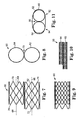
- Figure 6 illustrates the stent assembly 10 with stent barrels 12, 14 in an at least partially compressed condition.
- the stent barrels 12, 14 may be compressed in this manner prior to implantation in a patient, for example, and can be expanded into the mitral or tricuspid valve space during the surgical procedure.
- stent barrels 12, 14 are connected to or extend from each other at common area 20.
- the stent barrels may be connected along their entire lengths at the common area 20, or may instead be attached along only a portion of their lengths.
- the stent barrels 12, 14 may be manufactured as separate components, then bonded, adhered, welded, or otherwise attached to each other at one or more points along the length of common area 20.
- they may be attached or intertwined with each other a limited number of the rows of stent wires.
- the stent barrels 12, 14 may be attached or intertwined at every point where they contact or are otherwise adjacent to each other along their lengths.
- the stent barrels 12, 14 may be manufactured or assembled in such a way that the wires of the stent barrels 12, 14 are woven to intersect or connect in this area during the formation of those two barrels.
- the barrels 12, 14 are formed as portions of an integrated wire structure and therefore are not formed as separate components that need to be attached or secured to each other.
- two separate stent barrels are positioned in a desired location relative to each other, then a separate device or structure, such as a mechanical strut, is positioned for attachment to both stent barrels, thereby connecting them to each other in a double-barrel system of the type shown.
- first edge 22 of stent barrel 12 is shorter than second edge 24 of stent barrel 12.
- the lengths of these two portions are designed to be different in order to accommodate certain anatomical structures, which are described with further reference to Figures 4 and 5 .
- FIG. 4 illustrates a portion of a heart 40, with a stent assembly 10 of the invention positioned therein.
- heart 40 includes a left atrium 42, a left ventricle 44, a mitral valve 46 and an aortic valve 48.
- the broken lines of mitral valve 46 illustrate its native leaflets as they would generally be configured in a closed position prior to implantation of stent assembly 10.
- mitral valve 46 includes a first leaflet 50 on the anterior side of the valve, and a second leaflet 52 on the posterior side of the valve.
- stent assembly 10 can be positioned in the area of mitral valve 46 when it is not functioning properly (to replace the mitral valve) in accordance with the invention, thereby pushing the leaflets 50, 52 out of the mitral valve space, such as are shown as leaflets 56 and 58, respectively.
- first stent barrel 12 is visible; however, the second stent barrel 14 would be positioned immediately behind stent barrel 12.
- first edge 22 of stent barrel 12 is positioned to move leaflet 50 on the anterior side of the valve out of the mitral valve space and to its position shown as leaflet 56
- second edge 24 of stent barrel 12 is positioned to move leaflet 52 on the posterior side of the valve out of the mitral valve space and to its position shown as leaflet 58.
- the first edge 22 of stent barrel 12 is provided with a length that is sufficiently short so that it does not push the leaflet 56 to a position in which it will interfere with blood flow through the aortic valve 48 and/or interfere with the actual movement or functioning of the leaflets of the aortic valve 48.
- first edge 22 of stent barrel 12 further is provided with a sufficient length to provide a suitable area of contact with the annulus of the mitral valve to help to maintain it in its desired position.
- one embodiment of the stent barrel 12 includes a top portion that extends into the left atrium 42 and a lower portion that moves the leaflet 36 out of the mitral valve space, yet allows a portion of leaflet 36 to extend freely beyond the first edge 22.
- the amount of the leaflet 56 that extends beyond the bottom of stent barrel 12 is preferably small enough that it does not substantially and/or detrimentally interfere with the functioning of the aortic valve 48. It is noted that the structure, features, and positioning of the stent barrel 14 of the stent assembly 10 can be similar or identical to that of stent barrel 12.
- Figures 7-11 illustrate another exemplary embodiment of a stent assembly 60 of the invention, which includes a first stent barrel 62 and a second stent barrel 64, which are arranged so that a longitudinal axis 66 of stent barrel 62 is generally parallel to a longitudinal axis 68 of stent barrel 64.
- Stent barrel 62 is connected to stent barrel 64 along at least a portion of its length at a common area 70.
- stent barrel 62 is not tapered along its length, but instead extends as a continuous cylinder shape from its first end 72 to its second end 74.
- stent barrel 64 is not tapered along its length, but instead extends as a continuous cylinder shape from a first end 76 to a second end 78. As shown in the figure, the distance between first and second ends 72, 74 is greater then the distance between first and second ends 76, 78 so that the first stent barrel 62 is longer than the second stent barrel 64.
- the diameters of the first and second stent barrels 62, 64 can be essentially the same as each other when expanded, or may be different, depending on the anatomy of the patient in which the stent assembly will be implanted, the implantation techniques used, and other factors.
- first stent barrel 62 is generally aligned with the second end 78 of second stent barrel 64, while first end 72 of first stent barrel 62 is offset relative to the first end 76 of second stent barrel 64; however, it is contemplated that the second ends 74, 78 of these stent barrels are not aligned, but instead are also offset from each other.
- stent barrel 64 can be positioned in a different relative location along the length of stent barrel 62 in such a way that none of the ends of the stent barrels 62, 64 are aligned with each other.
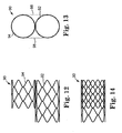
- Figure 11 illustrates stent assembly 60 positioned within the annulus of an exemplary mitral valve 80.
- the shorter stent barrel 64 is adjacent to an anterolateral portion 84 of mitral valve 80 and the longer stent barrel 62 is adjacent to a posteromedial portion 82 of mitral valve 80.
- interference of the stent assembly 60 with the functioning of the aortic valve and left ventricular outflow tract will be minimized, in accordance with the invention.
- the stent barrel 64 which is adjacent to the anterolateral portion 84 of the mitral valve 80, preferably is sufficiently short to minimize interference with the functioning of the aortic valve, yet is sufficiently long to provide enough contact area between the barrel 64 and the annulus to lessen the chances that the stent assembly 60 will become dislodged once it has been implanted.
- the stent barrel 62 which is adjacent to the posteromedial portion 82 of the mitral valve 80, can have any appropriate length that provides sufficient contact area with the annulus to lessen the chance that the stent assembly 60 will become dislodged once it has been implanted.
- the shorter barrel e.g., stent barrel 64 of Figure 7
- the shorter side of a tapered barrel e.g., first edge 22 of stent barrel 12 of Figure 1
- the shorter barrel is preferably aligned with or adjacent to the anterior annulus of the tricuspid valve and/or the septal annulus of the tricuspid valve and/or the anteroseptal commissure of the tricuspid valve.
- Figure 10 illustrates stent assembly 60 with the first and second stent barrels 62, 64 in their compressed conditions.
- the stent assembly may desirably be compressed to such a condition in order to aid in less invasive surgical techniques.
- stent barrels 62, 64 may lengthen at least slightly as compared to their uncompressed or expanded states, or may remain essentially the same length, depending on the construction of the stent barrels 62, 64. Exemplary devices and methods for delivering the stent assembly in such a compressed condition will be explained in further detail below.
- first and second stent barrels 62, 64 can include a tapered edge, a flared edge, or the like, such as is discussed above relative to edge 26 of Figures 1-5 .
- a stent assembly may include two stent barrels having different lengths, where the shorter barrel is additionally provided with a tapered edge to further minimize interference with the leaflet that is closest to the aortic valve.
- both of the stent barrels could have tapered edges, even if they have different lengths.
- Figures 12-14 illustrate another exemplary embodiment of a stent assembly 90 of the invention, which includes a first stent barrel 92 and a second stent barrel 94 that are connected or extend from each other along at least a portion of their lengths.
- the first stent barrel 92 is longer than the second stent barrel 94; however, in this embodiment the second stent barrel 94 is proportionally even shorter relative to the first stent barrel 92 as compared to the length relationship between the stent barrels 62, 64 of stent assembly 60. That is, the difference between the lengths of the barrels is greater than in the embodiment of Figure 7 .
- this embodiment of stent assembly 90 is substantially the same as that of the stent assembly 60, and the same variations and options described above are also contemplated for this embodiment.
- the differences in the lengths of the two stent barrels within a particular stent assembly of the invention may be greater or smaller than that shown in the Figures.
- stent assemblies described herein that include more than one stent barrel are generally shown and described as including stent barrels that are cylindrical, oval, or elliptical in shape; however, a number of different stent shapes are also contemplated.
- stent assembly 250 which includes a first stent barrel 252 and a second stent barrel 254.
- stent assembly 250 which includes a first stent barrel 252 and a second stent barrel 254.
- Each of these two stent barrels has a curvilinear surface (which can be designed to generally match the shape of the ends of the annulus of a mitral valve) and a generally flat or planar surface that results in more "squared off" corners where the flat surface meets the curvilinear surface.
- the flat surfaces of the stent barrels 252, 254 are attached or extend from each other at a central area 256. This arrangement provides more potential connection points between the two stent barrels since the surface area of contact is larger than is provided when two cylindrical stents are brought in contact with each other.
- stent assembly 260 which includes a first stent barrel 262 and a second stent barrel 264, where the second stent barrel 264 is larger than the first stent barrel 262.
- each of these stent barrels is shown to include a portion that is somewhat flat and in contact with a flat portion of the other stent barrel, although it is also contemplated that these stent barrels have curvilinear surfaces that are in contact with each other, basically along a tangent line.
- first stent barrel e.g., stent barrel 264
- second stent barrel e.g., stent barrel 262
- the two stent barrels can be attached to each other either before, during, or after expansion of the second stent barrel
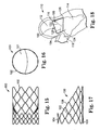
- FIGS 15-18 illustrate yet another embodiment, not part of the invention, of a stent assembly.
- a stent assembly 100 is shown, which includes a single stent barrel 102.
- the single barrel device can be used in a native valve, in a valve previously repaired with an annuloplasty band or ring, or in a valve replaced with a bioprosthetic device.
- Stent barrel 102 is tapered along its length, similar to the stent barrels described above relative to Figures 1-5 .
- stent barrel 102 is shorter at a first edge 104 than at a second edge 106, wherein first edge 104 is shown as the uppermost edge along the length of stent barrel 102, and second edge 106 is shown as the lowermost edge along the opposite side of the barrel 102 from the first edge 104.
- Stent barrel 102 further includes a tapered edge 108 that extends from the first edge 104 to the second edge 106.
- Edge 108 can be relatively straight or smooth when viewed from the side, as shown, or instead may be an edge that is curved or otherwise shaped between the edges 104, 106.
- the tapered edge 108 may be staggered, such as in a stair-step type of arrangement, rather than being smooth. Because the barrel 102 is relatively cylindrical in shape, the edge 108 is actually curvilinear between the edges 104, 106 when viewed in perspective. The length of second edge 106 may be only slightly greater than the length of first edge 104, or may be considerably longer, or even be equal in length, as desired and/or depending on the patient anatomy.
- This stent assembly 100 includes only a single stent barrel as compared to the dual-barrel embodiments described above; however, the tapered edge provides certain similar advantages to those of the dual-barrel design.
- FIG. 18 illustrates a portion of a heart 110, with a stent assembly 100 of the invention positioned therein.
- heart 110 includes a left atrium 112, a left ventricle 114, a mitral valve 116, and an aortic valve 118.
- the broken lines of mitral valve 116 illustrate its leaflets as they would generally be configured prior to implantation of stent assembly 100.
- mitral valve 116 includes a first leaflet 120 on the anterior side of the valve, and a second leaflet 122 on the posterior side of the valve.
- Stent assembly 100 can be positioned at the area of mitral valve 116 when it is not functioning properly (to replace the mitral valve), thereby pushing the first and second native leaflets 120, 122 out of the mitral valve space, such as are shown as leaflet 124 and 126, respectively.
- first edge 104 is positioned to move leaflet 120 on the anterior side of the valve out of the mitral valve space and to its position shown as leaflet 124
- second edge 106 of stent barrel 102 is positioned to move leaflet 122 on the posterior side of the valve out of the mitral valve space and to its position shown as leaflet 126.
- first edge 104 of stent barrel 102 is provided with a length that is sufficiently short so that it does not push the leaflet 124 to a position in which it will interfere with blood flow through the aortic valve 118 and/or interfere with the actual movement or functioning of the leaflets of the aortic valve 118; however, first edge 104 is further provided with a sufficient length to provide a suitable area of contact with the annulus of the mitral valve to help to maintain it in its desired position.
- one embodiment of the stent barrel 102 includes a top portion that extends into the left atrium 112 and a lower portion that moves the leaflet 124 out of the mitral valve space, yet allows a portion of leaflet 124 to extend freely beyond its lower edge.
- the amount of the leaflet 124 that extends beyond the bottom of stent barrel 102 is preferably small enough that it does not substantially and/or detrimentally interfere with the functioning of the aortic valve 118.
- Stent barrel 102 along with any of the other stent barrels of the present invention, may be configured so that they are relatively circular in cross section when in their expanded condition, as shown in the Figures.
- the stent barrels of the invention are at least slightly elliptical, oval, D-shaped, square, or differently shaped in cross-section when in their expanded condition.
- such a non-circular shape may be provided for the stent barrel in order to accommodate the shape of the mitral valve annulus, for example. That is, the shape of the stent assemblies can be designed and selected to provide both positional stability and a proper fit to the patient's anatomy.
- FIG. 16 illustrates stent assembly 100 with a two-leaflet valve 101 positioned within stent barrel 102.
- the leaflets may be attached in a generally central location in order to prevent prolapse of the leaflets into the atrium.
- another leaflet configuration may alternatively be used, such as a three-leaflet valve.
- valve segments may further be attached to each other where they are adjacent to each other in the stent assembly.
- the stent barrel may be provided with a center strut or support portion that spans across the open portion of the stent barrel, thereby dividing the center portion into two generally "D" shaped areas into which valve segments can be attached, for example. These areas can be the same or a different size and shape from each other, depending on where the center strut or support portion is positioned.
- FIGS 19 and 20 illustrate a docking or positioning feature that can optionally be used with any of the stent barrels of the invention, and is shown with particular use on a stent assembly 140.
- Stent assembly 140 includes a first stent barrel 142 and a second stent barrel 144 that is longer than the first stent barrel 142.
- First stent barrel 142 includes a first end 146 and a second end 148, and second stent barrel 144 includes a first end 150, which is generally aligned with the first end 146 of stent barrel 142, and a second end 152, which is offset from the second end 148 of first stent barrel 142.
- First stent barrel 142 further includes at least one flange portion 154 extending from the stent structure at the first end 146.
- one flange portion 154 extends from all or most of the points of each "V" structure at the first end 146, although it is contemplated that the stent barrel 142 include any number of flange portions 154.
- These flange portions 154 may be made of the same wire-type material from which the stent barrel 142 is made, and the flanges may be integrally molded or formed with the stent assembly 140.
- the flange portions 154 may be made of a different material and/or may comprise separate structures that are attached or connected to the structure of stent barrel 142.
- the flange portions 154 may also have a different size or shape than the triangular or V-shaped structures illustrated.
- the flange portions 154 may be semi-circular, rectangular, oblong, or the like, and may be considerably smaller or larger than shown.
- a different flange structure can be provided that is more continuous around the periphery of the stent barrel 142 (i.e., does not comprise a series of adjacent flanges).
- the second stent barrel 144 may include at least one flange portion 156 extending from the stent structure at its first end 150.
- the features and configurations described above relative to flange portions 154 are also contemplated for use with the flange portion(s) 156.
- These flange portions 156 may be the same as or different than the flange portions 154 in structure, shape, size, and the like, depending on the particular configuration and use of the stent assembly 140.
- the flange portion(s) 154 and/or 156 are preferably configured to be shaped and sized to provide an anchoring function for the stent assembly 140 when it is positioned to replace a valve.
- any flange portions that extend from the stent assembly 140 can provide interference with the walls of the left atrium 42, thereby inhibiting motion of the stent assembly 140.
- any of the stent assemblies discussed herein can further include structures that provide a fixation function for securing the stent assembly in its desired location.
- the stent assembly can include hooks, barbs, or the like that attach to a valve annulus upon deployment of the stent assembly.
- the stent assemblies of the invention may further include a cover or other material to prevent blood leakage into undesired areas of the heart.
- the stent assemblies that include two stent barrels may include a cover (e.g., tissue, polymer, or biocompatible fabric) that spans the area between the barrels on one or both sides of the stent assembly and/or covers the entire outer periphery of the stent barrels.
- a cover 98 is illustrated in broken lines in Figure 13 , and is shown on both sides of the stent assembly 90.
- System 130 includes an elongated balloon catheter having two inflatable balloons 132, 134 that are separated from each other near the distal end of the system 130. Balloons 132, 134 are connected for fluid communication with separate lumens that extend through the length of the catheter. These lumens provide for independent inflation and deflation of the balloons 132, 134 with a fluid, such as a radio-opaque fluid, during the process of deploying a stent assembly within a patient.
- a fluid such as a radio-opaque fluid
- the System 130 further includes a thin guide wire 136 that extends generally along the length of the catheter.
- the guide wire 136 may be, for example, a 0.089 cm diameter extra stiff guidewire as manufactured by Amplatzer of Golden Valley, Minnesota, which may be used in a conventional manner to guide the catheter to its desired implant location.
- System 130 may be at least partially disassembled for loading of a stent assembly onto the balloons 132, 134.
- a connector 138 which extends generally from one end of balloons 132, 134 and is attached to the guide wire 136 at its opposite end, can be disconnected from the guide wire to provide two separate balloons 132, 134 onto which two barrels of a double-barreled stent can be positioned.
- the stent barrels may then be crimped or compressed around the balloons 132, 134 until they are the desired size for implanting into a patient, and the connector 138 can then be reattached to the guide wire 136 and the system 130 can be inserted into the patient.
- balloons 132, 134 When the components of the system 130 are positioned relative to the mitral valve area of the patient, balloons 132, 134 may be inflated to thereby expand the compressed stent barrels to the desired size relative to the mitral valve annulus. After such stent expansion is complete, the balloons 132, 134 can be deflated and the system 130 can then be withdrawn from the patient.
- System 130 may further include one or more elongated sheaths (not shown) positioned over the catheter, which are large enough to surround one or both compressed sheaths when they are located over the balloon 132, 134.
- each sheath In their open or deployed configurations, each sheath is positioned along the catheter length so that balloons 132, 134 are not constrained and are therefore able to be inflated. Sliding each sheath toward the distal end of the system 130 so that it covers one or both balloons would provide a closed position of the device 10, which is the configuration in which the device would typically be inserted into a patient.
- a stent assembly having a single barrel, such as is shown in Figures 15-18 , for example. If such a single-barreled stent is to be implanted into a body opening that is not circular in shape, one exemplary delivery and stent-expansion device 200 that can be used for implantation of the stent is illustrated in Figures 22 and 23 .
- Device 200 generally includes a multi-balloon structure consisting of a central balloon 202, two side balloons 204, 206, and an outer balloon 208.
- the width of the device 200 along a first axis 210 is larger than the height of the device 200 along a second axis 212 that is generally perpendicular to the first axis 210.
- This type of arrangement is particularly adaptable to a stent that has a generally elliptical or oval shape, such as may be used in the replacement of a mitral valve, although it can be used for other stent opening shapes.
- the relative sizes of the multiple balloons may vary from the arrangement shown, depending on the shape and size of the stent in which the device 200 will be positioned.
- the side balloons 204, 206 will preferably be at least slightly smaller than the central balloon 202.
- the side balloons 204, 206 may be roughly the same size as the central balloon 202 and/or each of the side balloons 204, 206 may be identically or differently sized and shaped as the other of the side balloons 204, 206.
- the three balloons 202, 204, 206 can be independently expandable or may be connected to each other for simultaneous expansion of all the balloons.
- the balloons 202, 204, 206 will have their own inflation controls, which can be particularly useful to allow a surgeon to adjust the expansion of the stent in which it is being used.
- these inner balloons are preferably expanded prior to inflation of the outer balloon 208. That is, the balloons 202, 204, 206 are first inflated to expand a stent to its desired shape and size, then the outer balloon 208 is inflated to essentially "lock" or seal the stent in place. Due to the configuration of the inner balloons 202, 204, 206, the outer balloon 208 will generally conform to the outermost bounds of the inner balloons, thus maintaining a shape that is not circular.
- the outer balloon 208 provides additional pressure against the inside of the stent, such as stent 214 in Figure 22 , to keep the stent in its desired location.
- the balloons 202, 204, 206, 208 can be deflated and removed from the stent.
- the delivery devices of the invention may include more or less than three inner balloons and/or that the inner balloons may be positioned differently than shown and described.
- the outer balloon e.g., balloon 208
- more than one outer balloon may be used to encompass some or all of the inner balloons.
- the delivery device 200 may use fluids for inflation of the balloons, such as a radio-opaque fluid, during the process of deploying a stent assembly within a patient.
- FIGS 24 and 25 illustrate another embodiment not part of the invention of a stent 220 having a single barrel construction.
- Stent 220 is shown as having a generally circular shape; however, other shapes for the stent are also contemplated, such as elliptical, oval, or another shape that corresponds with an implantation site in a patient.
- Stent 220 includes a series of wires arranged as multiple zigzag structures having adjacent generally straight sections that meet one another at a curved or angled junction to form a "V" or "U” shaped structure, although other wire arrangements are contemplated.
- stent 220 includes a reinforced area 222, which may be provided through the use of a wire that is thicker than the remaining wires in the structure, for example.
- reinforced area 222 may be provided as another structure made of the same or a different material than the other wires of the stent 220, where the reinforced area 222 will be relatively stiff and/or constrained as compared to the areas above and below reinforced area 222.
- the reinforced area 222 may include a sealing gasket, such as tissue, fabric, polymer, metal mesh, or the like.
- the stent 220 can be designed so that the area 222 is the desired size for the annulus in which it will be positioned, while allowing the areas above and below the area 222 to expand or flare to a larger size to help to anchor the stent 220 in place.
- the stent 220 may include a gasket or other member around its exterior to provide for sealing against paravalvular leakage and to facilitate pannus in-growth for stabilization of the stent.
- a gasket or other member may alternatively or additionally be positioned on the interior portion of the stent or on the underside of a cuff provided on the stent.
- Figure 25 illustrates an exemplary delivery system for expanding the stent 220 as described above.
- the delivery system includes one or more balloons, where a balloon or portion of a balloon 224 is positioned on one side of the stent 220 and a balloon or portion of a balloon 226 is positioned on the opposite side of the stent 220.
- the stent 220 is relatively smaller in diameter at its reinforced or central area 222 than at the flared areas near the top and bottom of the stent 220.
- the balloon portions 224, 226 are relatively expandable to provide the necessary pressure to push the stent outwardly in this manner.
- the stent assemblies of the present invention may be positioned within the desired area of the heart via entry in a number of different ways.
- the stent assembly may be inserted transatrially, where entry may be done either percutaneously or in a minimally invasive technique on a beating heart in which access is through the side of the heart, or even through a standard open heart valve replacement procedure using heart-lung bypass and sternotomy where the described device would be used as an alternative to the standard replacement.
- the stent assembly may be inserted transapically, where entry again may be done either percutaneously or in a minimally invasive technique on a beating heart in which access is through the side of the heart.
- the stent assembly may be inserted transeptally, where entry can be done percutaneously, such as via the venous system into the right atrium and across a small hole in the septum to enter the left atrium.
- the delivery approaches may include balloons that would be used to facilitate the crossing of the mitral valve, thereby avoiding entanglement in the mitral apparatus.
- the description of the stent barrels herein is primarily directed to stents that are expanded through pressure from an expandable balloon positioned therein, it is also contemplated that the stent barrels of the present invention are self-expanding such that pressure is required to maintain the stent in its compressed condition, and removal of such pressure will allow these stents to expand to their desired size.
- the delivery system will be somewhat different than that described above relative to stents that are not self-expanding, and will instead include a system that only requires removal of external pressure (e.g., a compressive sheath) to allow the stents to expand, such as is the case with the delivery of stent grafts for aneurysms in the ascending aorta.
- a compressive sheath e.g., a compressive sheath
- These systems may also incorporate means for recapturing and/or repositioning the stent, if desired. In any case, it may be desirable to measure the mitral valve area with some type of spacer prior to installing the actual stent assembly in the heart of the patient.
- the stent assemblies of the invention may further include a means of facilitating orientation of the assembly, which can be particularly advantageous in cases where the stent assemblies include asymmetric features and configurations that must be properly oriented relative to the anatomy of the patient.
- the stent assemblies may include portions with materials that are opaque when viewed with various imaging techniques, such as echogenic coatings and radiopaque metals and polymers. Additionally or alternatively, the material used to fabricate the stent itself may be highly visible when using certain imaging techniques so that the user has a clear visibility of the orientation of the device prior to and during deployment.
Landscapes
- Health & Medical Sciences (AREA)
- Engineering & Computer Science (AREA)
- Cardiology (AREA)
- Biomedical Technology (AREA)
- Heart & Thoracic Surgery (AREA)
- Transplantation (AREA)
- Oral & Maxillofacial Surgery (AREA)
- Vascular Medicine (AREA)
- Life Sciences & Earth Sciences (AREA)
- Animal Behavior & Ethology (AREA)
- General Health & Medical Sciences (AREA)
- Public Health (AREA)
- Veterinary Medicine (AREA)
- Mechanical Engineering (AREA)
- Prostheses (AREA)
Claims (15)
- Zusammenpressbare und ausdehnbare Stent-Anordnung (10), die zur Implantation in ein Herz eines Patienten für einen Herzklappenersatz ausgebildet ist, wobei die Stent-Anordnung umfasst:eine erste Stent-Trommel (12), die eine röhrenförmige Struktur umfasst, die in radialer Richtung zusammenpressbar und ausdehnbar ist und die eine Außenfläche mit einer Peripherie umfasst, wobei ein erster Abschnitt (24) der Peripherie der ersten Stent-Trommel (12) eine erste Länge hat und ein zweiter Abschnitt (22) der Peripherie der ersten Stent-Trommel eine zweite Länge hat, die geringer als die erste Länge ist, und wobei ferner die erste Stent-Trommel (12) eine konisch zulaufende Kante (26) umfasst, die sich vom ersten Abschnitt (24) der Peripherie der ersten Stent-Trommel zum zweiten Abschnitt (22) der Peripherie der ersten Stent-Trommel erstreckt; undeine zweite Stent-Trommel (14) neben der ersten Stent-Trommel (12) und von dieser aus verlaufend, wobei die zweite Stent-Trommel (14) eine röhrenförmige Struktur umfasst, die in radialer Richtung zusammenpressbar und ausdehnbar ist und die eine Außenfläche mit einer Peripherie umfasst, wobei ein erster Abschnitt (30) der Peripherie der zweiten Stent-Trommel eine erste Länge hat und ein zweiter Abschnitt (28) der Peripherie der zweiten Stent-Trommel eine zweite Länge hat, die geringer als die erste Länge ist, und wobei ferner die zweite Stent-Trommel eine konisch zulaufende Kante umfasst, die sich vom ersten Abschnitt (30) der Peripherie der zweiten Stent-Trommel zum zweiten Abschnitt (28) der Peripherie der zweiten Stent-Trommel erstreckt.
- Stent-Anordnung nach Anspruch 1, wobei die erste Stent-Trommel (12) dieselbe erste Länge, dieselbe zweite Länge und dieselben Außenumfangsabmessungen wie die zweite Stent-Trommel (14) hat.
- Stent-Anordnung nach Anspruch 1, wobei sich die erste und zweite Stent-Trommel (12, 14) zueinander entlang einer Tangentiallinie erstrecken, die im Allgemeinen senkrecht zu einer radialen Ausdehnungsrichtung der ersten und zweiten Stent-Trommel (12, 14) verläuft.
- Stent-Anordnung nach Anspruch 1, wobei die erste und zweite Stent-Trommel (12, 14) jeweils eine Reihe von Drähten umfassen, die entlang einer Tangentiallinie verwoben sind, die in einer im Allgemeinen senkrechten Richtung zu der radialen Ausdehnungsrichtung der ersten und zweiten Stent-Trommel verläuft.
- Stent-Anordnung nach Anspruch 1, wobei die erste und zweite Stent-Trommel (12, 14) separate Komponenten umfassen, die entlang mindestens einem Abschnitt ihrer Längen mechanisch miteinander verbunden sind, um die erste Stent-Trommel (12) an der zweiten Stent-Trommel (14) zu befestigen.
- Stent-Anordnung nach Anspruch 1, wobei die erste Längsachse (16), die sich entlang der Länge der ersten Stent-Trommel (12) erstreckt, im Allgemeinen parallel zu einer zweiten Längsachse (18) verläuft, die sich entlang der Länge der zweiten Stent-Trommel (14) erstreckt.
- Stent-Anordnung nach Anspruch 1, wobei mindestens eine der ersten und zweiten Stent-Trommel (12, 14) zylindrisch ist.
- Stent-Anordnung nach Anspruch 7, wobei die erste und zweite Stent-Trommel (12, 14) im Allgemeinen dieselbe Querschnittsform und Größe haben.
- Stent-Anordnung nach Anspruch 1, wobei die erste Stent-Trommel (12) eine andere Querschnittsform als die zweite Stent-Trommel (14) hat.
- Stent-Anordnung nach Anspruch 1, wobei die erste Stent-Trommel (142) ein erstes Ende (146) mit mindestens einem Flanschabschnitt (154) aufweist, der sich in einem Winkel von diesem erstreckt.
- Stent-Anordnung nach Anspruch 10, wobei der mindestens eine Flanschabschnitt (154) eine Reihe von benachbarten Strukturen aufweist, die voneinander um mindestens einen Abschnitt der Peripherie der ersten Stent-Trommel (142) am ersten Ende (146) beabstandet sind.
- Stent-Anordnung nach Anspruch 10, wobei die zweite Stent-Trommel (144) ein erstes Ende (150) mit mindestens einem Flanschabschnitt (156) aufweist, der sich in einem Winkel von diesem erstreckt.
- Stent-Anordnung nach Anspruch 1, wobei die erste Stent-Trommel (62) relativ zu der zweiten Stent-Trommel (64) in eine Richtung versetzt ist, die parallel zu einer Längsachse (66, 68) der ersten und zweiten Stent-Trommel (62, 64) verläuft.
- Zusammenpressbare und ausdehnbare Stent-Anordnung (60), die zur Implantation in ein Herz eines Patienten für einen Herzklappenersatz ausgebildet ist, wobei die Stent-Anordnung umfasst:eine erste Stent-Trommel (62), die eine erste Länge und eine röhrenförmige Struktur umfasst, die in radialer Richtung zusammenpressbar und ausdehnbar ist; undeine zweite Stent-Trommel (64), die eine zweite Länge umfasst, die geringer als die erste Länge ist, und eine röhrenförmige Struktur, die in radialer Richtung zusammenpressbar und ausdehnbar ist, wobei die zweite Stent-Trommel (64) neben der ersten Stent-Trommel (62) liegt und sich von dieser entlang einer Tangentiallinie erstreckt, die in einer im Allgemeinen senkrechten Richtung zu der radialen Ausdehnungsrichtung der ersten und zweiten Stent-Trommel (62, 64) verläuft.
- Stent-Anordnung nach Anspruch 14, wobei die Tangentiallinie, entlang der sich die erste und zweite Stent-Trommel (62, 64) zueinander erstrecken, im Allgemeinen parallel zu einer ersten Längsachse und einer zweiten Längsachse ist, die entlang der Länge der ersten bzw. der zweiten Stent-Trommel verlaufen.
Priority Applications (1)
| Application Number | Priority Date | Filing Date | Title |
|---|---|---|---|
| EP11192376.9A EP2444031B1 (de) | 2007-01-19 | 2008-01-17 | Stentanbringungsvorrichtung |
Applications Claiming Priority (2)
| Application Number | Priority Date | Filing Date | Title |
|---|---|---|---|
| US88135107P | 2007-01-19 | 2007-01-19 | |
| PCT/US2008/000585 WO2008091515A2 (en) | 2007-01-19 | 2008-01-17 | Stented heart valve devices and methods for atrioventricular valve replacement |
Related Child Applications (2)
| Application Number | Title | Priority Date | Filing Date |
|---|---|---|---|
| EP11192376.9A Division EP2444031B1 (de) | 2007-01-19 | 2008-01-17 | Stentanbringungsvorrichtung |
| EP11192376.9 Division-Into | 2011-12-07 |
Publications (2)
| Publication Number | Publication Date |
|---|---|
| EP2111190A2 EP2111190A2 (de) | 2009-10-28 |
| EP2111190B1 true EP2111190B1 (de) | 2013-10-09 |
Family
ID=39387231
Family Applications (2)
| Application Number | Title | Priority Date | Filing Date |
|---|---|---|---|
| EP08724552.8A Ceased EP2111190B1 (de) | 2007-01-19 | 2008-01-17 | Gestentete Herzklappenvorrichtungen für atrioventrikulären Klappenersatz |
| EP11192376.9A Ceased EP2444031B1 (de) | 2007-01-19 | 2008-01-17 | Stentanbringungsvorrichtung |
Family Applications After (1)
| Application Number | Title | Priority Date | Filing Date |
|---|---|---|---|
| EP11192376.9A Ceased EP2444031B1 (de) | 2007-01-19 | 2008-01-17 | Stentanbringungsvorrichtung |
Country Status (3)
| Country | Link |
|---|---|
| US (4) | US9510943B2 (de) |
| EP (2) | EP2111190B1 (de) |
| WO (1) | WO2008091515A2 (de) |
Cited By (19)
| Publication number | Priority date | Publication date | Assignee | Title |
|---|---|---|---|---|
| US9034032B2 (en) | 2011-10-19 | 2015-05-19 | Twelve, Inc. | Prosthetic heart valve devices, prosthetic mitral valves and associated systems and methods |
| US9125740B2 (en) | 2011-06-21 | 2015-09-08 | Twelve, Inc. | Prosthetic heart valve devices and associated systems and methods |
| US9421098B2 (en) | 2010-12-23 | 2016-08-23 | Twelve, Inc. | System for mitral valve repair and replacement |
| US9579198B2 (en) | 2012-03-01 | 2017-02-28 | Twelve, Inc. | Hydraulic delivery systems for prosthetic heart valve devices and associated methods |
| US10856984B2 (en) | 2017-08-25 | 2020-12-08 | Neovasc Tiara Inc. | Sequentially deployed transcatheter mitral valve prosthesis |
| US10940001B2 (en) | 2012-05-30 | 2021-03-09 | Neovasc Tiara Inc. | Methods and apparatus for loading a prosthesis onto a delivery system |
| US11311376B2 (en) | 2019-06-20 | 2022-04-26 | Neovase Tiara Inc. | Low profile prosthetic mitral valve |
| US11357622B2 (en) | 2016-01-29 | 2022-06-14 | Neovase Tiara Inc. | Prosthetic valve for avoiding obstruction of outflow |
| US11389291B2 (en) | 2013-04-04 | 2022-07-19 | Neovase Tiara Inc. | Methods and apparatus for delivering a prosthetic valve to a beating heart |
| US11413139B2 (en) | 2011-11-23 | 2022-08-16 | Neovasc Tiara Inc. | Sequentially deployed transcatheter mitral valve prosthesis |
| US11419720B2 (en) | 2010-05-05 | 2022-08-23 | Neovasc Tiara Inc. | Transcatheter mitral valve prosthesis |
| US11464631B2 (en) | 2016-11-21 | 2022-10-11 | Neovasc Tiara Inc. | Methods and systems for rapid retraction of a transcatheter heart valve delivery system |
| US11491006B2 (en) | 2019-04-10 | 2022-11-08 | Neovasc Tiara Inc. | Prosthetic valve with natural blood flow |
| US11497602B2 (en) | 2012-02-14 | 2022-11-15 | Neovasc Tiara Inc. | Methods and apparatus for engaging a valve prosthesis with tissue |
| US11602429B2 (en) | 2019-04-01 | 2023-03-14 | Neovasc Tiara Inc. | Controllably deployable prosthetic valve |
| US11737872B2 (en) | 2018-11-08 | 2023-08-29 | Neovasc Tiara Inc. | Ventricular deployment of a transcatheter mitral valve prosthesis |
| US11779742B2 (en) | 2019-05-20 | 2023-10-10 | Neovasc Tiara Inc. | Introducer with hemostasis mechanism |
| US11998447B2 (en) | 2019-03-08 | 2024-06-04 | Neovasc Tiara Inc. | Retrievable prosthesis delivery system |
| US12109111B2 (en) | 2015-12-15 | 2024-10-08 | Neovasc Tiara Inc. | Transseptal delivery system |
Families Citing this family (387)
| Publication number | Priority date | Publication date | Assignee | Title |
|---|---|---|---|---|
| DK124690D0 (da) * | 1990-05-18 | 1990-05-18 | Henning Rud Andersen | Klapprotes til implantering i kroppen for erstatning af naturlig klap samt kateter til brug ved implantering af en saadan klapprotese |
| US6006134A (en) * | 1998-04-30 | 1999-12-21 | Medtronic, Inc. | Method and device for electronically controlling the beating of a heart using venous electrical stimulation of nerve fibers |
| EP0850607A1 (de) | 1996-12-31 | 1998-07-01 | Cordis Corporation | Klappenprothese zur Implantation in Körperkanälen |
| US7018406B2 (en) | 1999-11-17 | 2006-03-28 | Corevalve Sa | Prosthetic valve for transluminal delivery |
| US8016877B2 (en) | 1999-11-17 | 2011-09-13 | Medtronic Corevalve Llc | Prosthetic valve for transluminal delivery |
| US8579966B2 (en) | 1999-11-17 | 2013-11-12 | Medtronic Corevalve Llc | Prosthetic valve for transluminal delivery |
| US8241274B2 (en) | 2000-01-19 | 2012-08-14 | Medtronic, Inc. | Method for guiding a medical device |
| US6692513B2 (en) | 2000-06-30 | 2004-02-17 | Viacor, Inc. | Intravascular filter with debris entrapment mechanism |
| US7749245B2 (en) | 2000-01-27 | 2010-07-06 | Medtronic, Inc. | Cardiac valve procedure methods and devices |
| US6454799B1 (en) | 2000-04-06 | 2002-09-24 | Edwards Lifesciences Corporation | Minimally-invasive heart valves and methods of use |
| US6733525B2 (en) | 2001-03-23 | 2004-05-11 | Edwards Lifesciences Corporation | Rolled minimally-invasive heart valves and methods of use |
| US7544206B2 (en) | 2001-06-29 | 2009-06-09 | Medtronic, Inc. | Method and apparatus for resecting and replacing an aortic valve |
| US8623077B2 (en) | 2001-06-29 | 2014-01-07 | Medtronic, Inc. | Apparatus for replacing a cardiac valve |
| US8771302B2 (en) | 2001-06-29 | 2014-07-08 | Medtronic, Inc. | Method and apparatus for resecting and replacing an aortic valve |
| FR2826863B1 (fr) | 2001-07-04 | 2003-09-26 | Jacques Seguin | Ensemble permettant la mise en place d'une valve prothetique dans un conduit corporel |
| FR2828091B1 (fr) | 2001-07-31 | 2003-11-21 | Seguin Jacques | Ensemble permettant la mise en place d'une valve prothetique dans un conduit corporel |
| US7097659B2 (en) | 2001-09-07 | 2006-08-29 | Medtronic, Inc. | Fixation band for affixing a prosthetic heart valve to tissue |
| CA2769574C (en) | 2001-10-04 | 2014-12-23 | Neovasc Medical Ltd. | Flow reducing implant |
| US6893460B2 (en) | 2001-10-11 | 2005-05-17 | Percutaneous Valve Technologies Inc. | Implantable prosthetic valve |
| US20050075725A1 (en) | 2003-10-02 | 2005-04-07 | Rowe Stanton J. | Implantable prosthetic valve with non-laminar flow |
| US9579194B2 (en) | 2003-10-06 | 2017-02-28 | Medtronic ATS Medical, Inc. | Anchoring structure with concave landing zone |
| IL158960A0 (en) | 2003-11-19 | 2004-05-12 | Neovasc Medical Ltd | Vascular implant |
| ITTO20040135A1 (it) | 2004-03-03 | 2004-06-03 | Sorin Biomedica Cardio Spa | Protesi valvolare cardiaca |
| EP1753374A4 (de) | 2004-04-23 | 2010-02-10 | 3F Therapeutics Inc | Implantierbares protheseventil |
| US20060052867A1 (en) | 2004-09-07 | 2006-03-09 | Medtronic, Inc | Replacement prosthetic heart valve, system and method of implant |
| JP2008513060A (ja) | 2004-09-14 | 2008-05-01 | エドワーズ ライフサイエンシーズ アーゲー | 心臓弁逆流の処置のためのデバイスおよび方法 |
| EP2491891A3 (de) | 2004-10-02 | 2013-03-20 | Endoheart AG | Vorrichtungen zum Schutz vor Embolien und zur Mitralklappenreparatur |
| US8562672B2 (en) * | 2004-11-19 | 2013-10-22 | Medtronic, Inc. | Apparatus for treatment of cardiac valves and method of its manufacture |
| DE102005003632A1 (de) | 2005-01-20 | 2006-08-17 | Fraunhofer-Gesellschaft zur Förderung der angewandten Forschung e.V. | Katheter für die transvaskuläre Implantation von Herzklappenprothesen |
| ITTO20050074A1 (it) | 2005-02-10 | 2006-08-11 | Sorin Biomedica Cardio Srl | Protesi valvola cardiaca |
| US7914569B2 (en) | 2005-05-13 | 2011-03-29 | Medtronics Corevalve Llc | Heart valve prosthesis and methods of manufacture and use |
| WO2007038540A1 (en) | 2005-09-26 | 2007-04-05 | Medtronic, Inc. | Prosthetic cardiac and venous valves |
| AU2006315812B2 (en) | 2005-11-10 | 2013-03-28 | Cardiaq Valve Technologies, Inc. | Balloon-expandable, self-expanding, vascular prosthesis connecting stent |
| EP2004095B1 (de) | 2006-03-28 | 2019-06-12 | Medtronic, Inc. | Herzklappenprothese aus herzbeutelmaterial und herstellungsverfahren dafür |
| WO2008013915A2 (en) | 2006-07-28 | 2008-01-31 | Arshad Quadri | Percutaneous valve prosthesis and system and method for implanting same |
| US9408607B2 (en) | 2009-07-02 | 2016-08-09 | Edwards Lifesciences Cardiaq Llc | Surgical implant devices and methods for their manufacture and use |
| EP3360509B1 (de) | 2006-07-31 | 2022-06-22 | Syntheon TAVR, LLC | Verschliessbare endovaskuläre implantate |
| US9585743B2 (en) | 2006-07-31 | 2017-03-07 | Edwards Lifesciences Cardiaq Llc | Surgical implant devices and methods for their manufacture and use |
| US8834564B2 (en) | 2006-09-19 | 2014-09-16 | Medtronic, Inc. | Sinus-engaging valve fixation member |
| US11304800B2 (en) | 2006-09-19 | 2022-04-19 | Medtronic Ventor Technologies Ltd. | Sinus-engaging valve fixation member |
| US8052750B2 (en) | 2006-09-19 | 2011-11-08 | Medtronic Ventor Technologies Ltd | Valve prosthesis fixation techniques using sandwiching |
| WO2008047354A2 (en) | 2006-10-16 | 2008-04-24 | Ventor Technologies Ltd. | Transapical delivery system with ventriculo-arterial overflow bypass |
| EP2104470B1 (de) | 2006-12-06 | 2022-10-26 | Medtronic Corevalve, LLC. | Systeme und verfahren zur transapikalen freisetzung einer ringverankerten selbstexpandierenden klappe |
| US8236045B2 (en) | 2006-12-22 | 2012-08-07 | Edwards Lifesciences Corporation | Implantable prosthetic valve assembly and method of making the same |
| EP2111190B1 (de) | 2007-01-19 | 2013-10-09 | Medtronic, Inc. | Gestentete Herzklappenvorrichtungen für atrioventrikulären Klappenersatz |
| EP2129333B1 (de) | 2007-02-16 | 2019-04-03 | Medtronic, Inc | Herzklappenprothese |
| US7896915B2 (en) | 2007-04-13 | 2011-03-01 | Jenavalve Technology, Inc. | Medical device for treating a heart valve insufficiency |
| FR2915087B1 (fr) | 2007-04-20 | 2021-11-26 | Corevalve Inc | Implant de traitement d'une valve cardiaque, en particulier d'une valve mitrale, materiel inculant cet implant et materiel de mise en place de cet implant. |
| US9566178B2 (en) | 2010-06-24 | 2017-02-14 | Edwards Lifesciences Cardiaq Llc | Actively controllable stent, stent graft, heart valve and method of controlling same |
| US8747458B2 (en) | 2007-08-20 | 2014-06-10 | Medtronic Ventor Technologies Ltd. | Stent loading tool and method for use thereof |
| DE102007043830A1 (de) | 2007-09-13 | 2009-04-02 | Lozonschi, Lucian, Madison | Herzklappenstent |
| US10856970B2 (en) | 2007-10-10 | 2020-12-08 | Medtronic Ventor Technologies Ltd. | Prosthetic heart valve for transfemoral delivery |
| US9848981B2 (en) | 2007-10-12 | 2017-12-26 | Mayo Foundation For Medical Education And Research | Expandable valve prosthesis with sealing mechanism |
| PL2628464T5 (pl) | 2007-12-14 | 2024-10-28 | Edwards Lifesciences Corporation | Zastawka protetyczna |
| US8157853B2 (en) | 2008-01-24 | 2012-04-17 | Medtronic, Inc. | Delivery systems and methods of implantation for prosthetic heart valves |
| US7972378B2 (en) | 2008-01-24 | 2011-07-05 | Medtronic, Inc. | Stents for prosthetic heart valves |
| EP2254512B1 (de) | 2008-01-24 | 2016-01-06 | Medtronic, Inc. | Marker für herzklappenprothesen |
| US9149358B2 (en) | 2008-01-24 | 2015-10-06 | Medtronic, Inc. | Delivery systems for prosthetic heart valves |
| US9393115B2 (en) | 2008-01-24 | 2016-07-19 | Medtronic, Inc. | Delivery systems and methods of implantation for prosthetic heart valves |
| EP2254513B1 (de) | 2008-01-24 | 2015-10-28 | Medtronic, Inc. | Stents für herzklappenprothesen |
| WO2011104269A1 (en) | 2008-02-26 | 2011-09-01 | Jenavalve Technology Inc. | Stent for the positioning and anchoring of a valvular prosthesis in an implantation site in the heart of a patient |
| US9044318B2 (en) | 2008-02-26 | 2015-06-02 | Jenavalve Technology Gmbh | Stent for the positioning and anchoring of a valvular prosthesis |
| WO2009108355A1 (en) | 2008-02-28 | 2009-09-03 | Medtronic, Inc. | Prosthetic heart valve systems |
| US8313525B2 (en) | 2008-03-18 | 2012-11-20 | Medtronic Ventor Technologies, Ltd. | Valve suturing and implantation procedures |
| US8430927B2 (en) * | 2008-04-08 | 2013-04-30 | Medtronic, Inc. | Multiple orifice implantable heart valve and methods of implantation |
| US8312825B2 (en) | 2008-04-23 | 2012-11-20 | Medtronic, Inc. | Methods and apparatuses for assembly of a pericardial prosthetic heart valve |
| US8696743B2 (en) | 2008-04-23 | 2014-04-15 | Medtronic, Inc. | Tissue attachment devices and methods for prosthetic heart valves |
| US20090276040A1 (en) | 2008-05-01 | 2009-11-05 | Edwards Lifesciences Corporation | Device and method for replacing mitral valve |
| US8728153B2 (en) * | 2008-05-14 | 2014-05-20 | Onset Medical Corporation | Expandable transapical sheath and method of use |
| US8668668B2 (en) * | 2008-05-14 | 2014-03-11 | Onset Medical Corporation | Expandable iliac sheath and method of use |
| ATE554731T1 (de) | 2008-05-16 | 2012-05-15 | Sorin Biomedica Cardio Srl | Atraumatische prothetische herzklappenprothese |
| CA3272239A1 (en) | 2008-06-06 | 2025-10-28 | Edwards Lifesciences Corporation | Low profile transcatheter heart valve |
| US8323335B2 (en) | 2008-06-20 | 2012-12-04 | Edwards Lifesciences Corporation | Retaining mechanisms for prosthetic valves and methods for using |
| US8652202B2 (en) | 2008-08-22 | 2014-02-18 | Edwards Lifesciences Corporation | Prosthetic heart valve and delivery apparatus |
| EP4018967B1 (de) | 2008-09-15 | 2025-09-03 | Medtronic Ventor Technologies Ltd | Herzklappenprothese mit identifikationsvorrichtungen zur leichteren radiografischen positionierung |
| US8721714B2 (en) | 2008-09-17 | 2014-05-13 | Medtronic Corevalve Llc | Delivery system for deployment of medical devices |
| US9314335B2 (en) | 2008-09-19 | 2016-04-19 | Edwards Lifesciences Corporation | Prosthetic heart valve configured to receive a percutaneous prosthetic heart valve implantation |
| US8287591B2 (en) * | 2008-09-19 | 2012-10-16 | Edwards Lifesciences Corporation | Transformable annuloplasty ring configured to receive a percutaneous prosthetic heart valve implantation |
| AU2009295960A1 (en) | 2008-09-29 | 2010-04-01 | Cardiaq Valve Technologies, Inc. | Heart valve |
| EP2341871B1 (de) | 2008-10-01 | 2017-03-22 | Edwards Lifesciences CardiAQ LLC | Abgabesystem für ein gefässimplantat |
| US8790387B2 (en) | 2008-10-10 | 2014-07-29 | Edwards Lifesciences Corporation | Expandable sheath for introducing an endovascular delivery device into a body |
| US8137398B2 (en) | 2008-10-13 | 2012-03-20 | Medtronic Ventor Technologies Ltd | Prosthetic valve having tapered tip when compressed for delivery |
| US8986361B2 (en) | 2008-10-17 | 2015-03-24 | Medtronic Corevalve, Inc. | Delivery system for deployment of medical devices |
| WO2010057262A1 (en) | 2008-11-21 | 2010-05-27 | Percutaneous Cardiovascular Solutions Pty Limited | Heart valve prosthesis and method |
| WO2010065265A2 (en) | 2008-11-25 | 2010-06-10 | Edwards Lifesciences Corporation | Apparatus and method for in situ expansion of prosthetic device |
| EP2201911B1 (de) | 2008-12-23 | 2015-09-30 | Sorin Group Italia S.r.l. | Erweiterbare Klappenprothese mit Verankerungsfortsätzen |
| US9402720B2 (en) | 2009-01-12 | 2016-08-02 | Valve Medical Ltd. | Modular percutaneous valve structure and delivery method |
| US20100217382A1 (en) * | 2009-02-25 | 2010-08-26 | Edwards Lifesciences | Mitral valve replacement with atrial anchoring |
| US20100217371A1 (en) * | 2009-02-26 | 2010-08-26 | Medtronic Vascular, Inc. | Device, System, and Method for Aiding Stent Valve Deployment |
| EP4119098A1 (de) | 2009-04-15 | 2023-01-18 | Edwards Lifesciences CardiAQ LLC | Gefässimplantat und freisetzungssystem |
| EP2246011B1 (de) | 2009-04-27 | 2014-09-03 | Sorin Group Italia S.r.l. | Prothetische Gefässleitung |
| CA2760461C (en) | 2009-04-29 | 2014-10-07 | The Cleveland Clinic Foundation | Apparatus and method for replacing a diseased cardiac valve |
| US8475522B2 (en) | 2009-07-14 | 2013-07-02 | Edwards Lifesciences Corporation | Transapical delivery system for heart valves |
| US8597343B2 (en) * | 2009-09-18 | 2013-12-03 | Medtronic Vascular, Inc. | Stent with constant stiffness along the length of the stent |
| US9730790B2 (en) | 2009-09-29 | 2017-08-15 | Edwards Lifesciences Cardiaq Llc | Replacement valve and method |
| US8808369B2 (en) | 2009-10-05 | 2014-08-19 | Mayo Foundation For Medical Education And Research | Minimally invasive aortic valve replacement |
| US12370044B2 (en) * | 2009-10-06 | 2025-07-29 | Reniva, Inc. | Systems and methods for treating luminal valves |
| US8449599B2 (en) | 2009-12-04 | 2013-05-28 | Edwards Lifesciences Corporation | Prosthetic valve for replacing mitral valve |
| WO2011072084A2 (en) | 2009-12-08 | 2011-06-16 | Avalon Medical Ltd. | Device and system for transcatheter mitral valve replacement |
| JP5837422B2 (ja) * | 2010-01-12 | 2015-12-24 | バルブ メディカル エルティーディーValve Medical Ltd | モジュール式経皮弁構造体及び送達方法 |
| US9072603B2 (en) * | 2010-02-24 | 2015-07-07 | Medtronic Ventor Technologies, Ltd. | Mitral prosthesis and methods for implantation |
| US9226826B2 (en) | 2010-02-24 | 2016-01-05 | Medtronic, Inc. | Transcatheter valve structure and methods for valve delivery |
| US9522062B2 (en) * | 2010-02-24 | 2016-12-20 | Medtronic Ventor Technologies, Ltd. | Mitral prosthesis and methods for implantation |
| US8206434B2 (en) | 2010-03-02 | 2012-06-26 | Medtronic Vascular, Inc. | Stent with sinusoidal wave form and orthogonal end and method for making same |
| US20110218615A1 (en) * | 2010-03-02 | 2011-09-08 | Medtronic Vascular, Inc. | Stent With Multi-Crown Constraint and Method for Ending Helical Wound Stents |
| US8795354B2 (en) | 2010-03-05 | 2014-08-05 | Edwards Lifesciences Corporation | Low-profile heart valve and delivery system |
| US8652204B2 (en) | 2010-04-01 | 2014-02-18 | Medtronic, Inc. | Transcatheter valve with torsion spring fixation and related systems and methods |
| US9241816B2 (en) | 2010-04-20 | 2016-01-26 | Shanghai Microport Medical (Group) Co., Ltd. | Stent for bifurcated vessel |
| CN102068331B (zh) * | 2010-04-20 | 2013-08-07 | 上海微创医疗器械(集团)有限公司 | 一种分叉血管支架 |
| US10856978B2 (en) | 2010-05-20 | 2020-12-08 | Jenavalve Technology, Inc. | Catheter system |
| IT1400327B1 (it) | 2010-05-21 | 2013-05-24 | Sorin Biomedica Cardio Srl | Dispositivo di supporto per protesi valvolari e corrispondente corredo. |
| WO2011147849A1 (en) | 2010-05-25 | 2011-12-01 | Jenavalve Technology Inc. | Prosthetic heart valve and transcatheter delivered endoprosthesis comprising a prosthetic heart valve and a stent |
| WO2011159342A1 (en) * | 2010-06-17 | 2011-12-22 | St. Jude Medical, Inc. | Collapsible heart valve with angled frame |
| AU2011271007A1 (en) | 2010-06-21 | 2013-01-31 | Cardiaq Valve Technologies, Inc. | Replacement heart valve |
| CA2804771C (en) | 2010-07-09 | 2018-02-20 | Highlife Sas | Transcatheter atrio-ventricular valve prosthesis |
| US8328072B2 (en) | 2010-07-19 | 2012-12-11 | Medtronic Vascular, Inc. | Method for forming a wave form used to make wound stents |
| ES3023659T3 (en) | 2010-07-23 | 2025-06-02 | Edwards Lifesciences Corp | Retaining mechanisms for prosthetic valves |
| EP2611388B1 (de) | 2010-09-01 | 2022-04-27 | Medtronic Vascular Galway | Stützstruktur für eine herzklappenprothese |
| WO2012040655A2 (en) | 2010-09-23 | 2012-03-29 | Cardiaq Valve Technologies, Inc. | Replacement heart valves, delivery devices and methods |
| CA3020195C (en) | 2010-10-05 | 2020-10-27 | Edwards Lifesciences Corporation | Prosthetic heart valve |
| EP2486894B1 (de) | 2011-02-14 | 2021-06-09 | Sorin Group Italia S.r.l. | Vorrichtung zur nahtlosen Verankerung von Herzklappenprothesen |
| ES2641902T3 (es) | 2011-02-14 | 2017-11-14 | Sorin Group Italia S.R.L. | Dispositivo de anclaje sin sutura para prótesis valvulares cardiacas |
| US9155619B2 (en) | 2011-02-25 | 2015-10-13 | Edwards Lifesciences Corporation | Prosthetic heart valve delivery apparatus |
| EP4119095A1 (de) | 2011-03-21 | 2023-01-18 | Cephea Valve Technologies, Inc. | Scheibenförmige ventilvorrichtung |
| US12502276B2 (en) | 2011-05-16 | 2025-12-23 | Edwards Lifesciences Corporation | Inversion delivery device and method for a prosthesis |
| US20120316632A1 (en) * | 2011-06-13 | 2012-12-13 | Bulang Gao | Retrievable covered stent for bifurcation aneurysms |
| WO2012173995A2 (en) | 2011-06-15 | 2012-12-20 | St. Jude Medical, Inc. | Multi-layer stent |
| US9296034B2 (en) | 2011-07-26 | 2016-03-29 | Medtronic Vascular, Inc. | Apparatus and method for forming a wave form for a stent from a wire |
| US9339384B2 (en) | 2011-07-27 | 2016-05-17 | Edwards Lifesciences Corporation | Delivery systems for prosthetic heart valve |
| EP3705090B1 (de) * | 2011-08-11 | 2023-12-06 | Tendyne Holdings, Inc. | Verbesserungen für prothesenklappen und damit zusammenhängende erfindungen |
| US9763780B2 (en) | 2011-10-19 | 2017-09-19 | Twelve, Inc. | Devices, systems and methods for heart valve replacement |
| US11202704B2 (en) | 2011-10-19 | 2021-12-21 | Twelve, Inc. | Prosthetic heart valve devices, prosthetic mitral valves and associated systems and methods |
| JP6151705B2 (ja) | 2011-10-19 | 2017-06-21 | トゥエルヴ, インコーポレイテッド | 心臓弁置換のためのデバイス、システムおよび方法 |
| US10016271B2 (en) | 2011-10-19 | 2018-07-10 | Twelve, Inc. | Prosthetic heart valve devices, prosthetic mitral valves and associated systems and methods |
| US9655722B2 (en) | 2011-10-19 | 2017-05-23 | Twelve, Inc. | Prosthetic heart valve devices, prosthetic mitral valves and associated systems and methods |
| US9827093B2 (en) | 2011-10-21 | 2017-11-28 | Edwards Lifesciences Cardiaq Llc | Actively controllable stent, stent graft, heart valve and method of controlling same |
| US12364596B2 (en) | 2011-10-21 | 2025-07-22 | Edwards Lifesciences Cardiaq Llc | Actively controllable stent, stent graft, heart valve and method of controlling same |
| EP2775958B1 (de) | 2011-11-11 | 2017-01-04 | Bolton Medical, Inc. | Universelle endovaskuläre implantate |
| EP4049625B1 (de) | 2011-12-09 | 2025-01-08 | Edwards Lifesciences Corporation | Herzklappenprothese mit verbesserten kommissurstützen |
| US8652145B2 (en) | 2011-12-14 | 2014-02-18 | Edwards Lifesciences Corporation | System and method for crimping a prosthetic valve |
| US9827092B2 (en) | 2011-12-16 | 2017-11-28 | Tendyne Holdings, Inc. | Tethers for prosthetic mitral valve |
| EP2609893B1 (de) | 2011-12-29 | 2014-09-03 | Sorin Group Italia S.r.l. | Kit zur Implantation von prothetischen Gefäßleitungen |
| EP3424469A1 (de) | 2012-02-22 | 2019-01-09 | Syntheon TAVR, LLC | Aktiv steuerbarer stent, stentgraft und herzklappe |
| EP2886083B2 (de) * | 2012-03-23 | 2024-06-19 | Corcym S.r.l. | Zusammenklappbare Klappenprothese |
| US9005270B2 (en) | 2012-03-27 | 2015-04-14 | Medtronic Vascular, Inc. | High metal to vessel ratio stent and method |
| US8911490B2 (en) | 2012-03-27 | 2014-12-16 | Medtronic Vascular, Inc. | Integrated mesh high metal to vessel ratio stent and method |
| US9393136B2 (en) | 2012-03-27 | 2016-07-19 | Medtronic Vascular, Inc. | Variable zone high metal to vessel ratio stent and method |
| US9295547B2 (en) | 2012-03-28 | 2016-03-29 | Medtronic Vascular Galway | Prosthesis for transcatheter valve implantation |
| US9023098B2 (en) * | 2012-03-28 | 2015-05-05 | Medtronic, Inc. | Dual valve prosthesis for transcatheter valve implantation |
| US9066800B2 (en) | 2012-03-28 | 2015-06-30 | Medtronic, Inc. | Dual valve prosthesis for transcatheter valve implantation |
| US8926694B2 (en) * | 2012-03-28 | 2015-01-06 | Medtronic Vascular Galway Limited | Dual valve prosthesis for transcatheter valve implantation |
| US9242290B2 (en) | 2012-04-03 | 2016-01-26 | Medtronic Vascular, Inc. | Method and apparatus for creating formed elements used to make wound stents |
| US9238260B2 (en) | 2012-04-18 | 2016-01-19 | Medtronic Vascular, Inc. | Method and apparatus for creating formed elements used to make wound stents |
| US9427315B2 (en) | 2012-04-19 | 2016-08-30 | Caisson Interventional, LLC | Valve replacement systems and methods |
| US9011515B2 (en) | 2012-04-19 | 2015-04-21 | Caisson Interventional, LLC | Heart valve assembly systems and methods |
| US9364351B2 (en) | 2012-04-23 | 2016-06-14 | Medtronic Vascular, Inc. | Method for forming a stent |
| US9883941B2 (en) | 2012-06-19 | 2018-02-06 | Boston Scientific Scimed, Inc. | Replacement heart valve |
| WO2014022124A1 (en) | 2012-07-28 | 2014-02-06 | Tendyne Holdings, Inc. | Improved multi-component designs for heart valve retrieval device, sealing structures and stent assembly |
| US9675454B2 (en) | 2012-07-30 | 2017-06-13 | Tendyne Holdings, Inc. | Delivery systems and methods for transcatheter prosthetic valves |
| ES2735536T3 (es) | 2012-08-10 | 2019-12-19 | Sorin Group Italia Srl | Una prótesis de válvula y un kit |
| ES2931210T3 (es) | 2012-11-21 | 2022-12-27 | Edwards Lifesciences Corp | Mecanismos de retención para válvulas cardiacas protésicas |
| EP2938292B1 (de) | 2012-12-31 | 2018-03-28 | Edwards Lifesciences Corporation | Zur erweiterung nach der implantation angepasste chirurgische herzklappen |
| US10543085B2 (en) | 2012-12-31 | 2020-01-28 | Edwards Lifesciences Corporation | One-piece heart valve stents adapted for post-implant expansion |
| US9439763B2 (en) | 2013-02-04 | 2016-09-13 | Edwards Lifesciences Corporation | Prosthetic valve for replacing mitral valve |
| US9168129B2 (en) | 2013-02-12 | 2015-10-27 | Edwards Lifesciences Corporation | Artificial heart valve with scalloped frame design |
| US10583002B2 (en) | 2013-03-11 | 2020-03-10 | Neovasc Tiara Inc. | Prosthetic valve with anti-pivoting mechanism |
| US20140277427A1 (en) | 2013-03-14 | 2014-09-18 | Cardiaq Valve Technologies, Inc. | Prosthesis for atraumatically grasping intralumenal tissue and methods of delivery |
| US9681951B2 (en) | 2013-03-14 | 2017-06-20 | Edwards Lifesciences Cardiaq Llc | Prosthesis with outer skirt and anchors |
| US9730791B2 (en) | 2013-03-14 | 2017-08-15 | Edwards Lifesciences Cardiaq Llc | Prosthesis for atraumatically grasping intralumenal tissue and methods of delivery |
| US10463489B2 (en) | 2013-04-02 | 2019-11-05 | Tendyne Holdings, Inc. | Prosthetic heart valve and systems and methods for delivering the same |
| US9486306B2 (en) | 2013-04-02 | 2016-11-08 | Tendyne Holdings, Inc. | Inflatable annular sealing device for prosthetic mitral valve |
| US11224510B2 (en) | 2013-04-02 | 2022-01-18 | Tendyne Holdings, Inc. | Prosthetic heart valve and systems and methods for delivering the same |
| US10478293B2 (en) | 2013-04-04 | 2019-11-19 | Tendyne Holdings, Inc. | Retrieval and repositioning system for prosthetic heart valve |
| JP6561044B2 (ja) | 2013-05-03 | 2019-08-14 | メドトロニック,インコーポレイテッド | 弁搬送ツール |
| EP2999435B1 (de) | 2013-05-20 | 2022-12-21 | Twelve, Inc. | Implantierbare herzklappenvorrichtungen, mitralklappenreparaturvorrichtungen sowie entsprechende systeme |
| ES2908132T3 (es) | 2013-05-20 | 2022-04-27 | Edwards Lifesciences Corp | Aparato de suministro de válvula cardiaca protésica |
| US9610159B2 (en) | 2013-05-30 | 2017-04-04 | Tendyne Holdings, Inc. | Structural members for prosthetic mitral valves |
| AU2014302505B2 (en) | 2013-06-25 | 2019-11-28 | Tendyne Holdings, Inc. | Thrombus management and structural compliance features for prosthetic heart valves |
| US9561103B2 (en) | 2013-07-17 | 2017-02-07 | Cephea Valve Technologies, Inc. | System and method for cardiac valve repair and replacement |
| WO2015013666A1 (en) | 2013-07-26 | 2015-01-29 | Cardiaq Valve Technologies, Inc. | Systems and methods for sealing openings in an anatomical wall |
| WO2015017689A1 (en) | 2013-08-01 | 2015-02-05 | Robert Vidlund | Epicardial anchor devices and methods |
| EP2835112B1 (de) | 2013-08-08 | 2021-01-27 | Sorin Group Italia S.r.l. | Herzklappenprothese |
| EP4578426A3 (de) | 2013-08-14 | 2025-09-03 | Mitral Valve Technologies Sàrl | Ersatzherzklappenvorrichtung und verfahren |
| WO2015028209A1 (en) | 2013-08-30 | 2015-03-05 | Jenavalve Technology Gmbh | Radially collapsible frame for a prosthetic valve and method for manufacturing such a frame |
| US10226333B2 (en) | 2013-10-15 | 2019-03-12 | Cedars-Sinai Medical Center | Anatomically-orientated and self-positioning transcatheter mitral valve |
| WO2015057995A2 (en) | 2013-10-16 | 2015-04-23 | Cedars-Sinai Medical Center | Modular dis-assembly of transcatheter valve replacement devices and uses thereof |
| WO2015058039A1 (en) | 2013-10-17 | 2015-04-23 | Robert Vidlund | Apparatus and methods for alignment and deployment of intracardiac devices |
| CN105611889A (zh) | 2013-10-17 | 2016-05-25 | 雪松-西奈医学中心 | 用于经皮治疗心脏瓣膜栓塞的装置 |
| US9421094B2 (en) | 2013-10-23 | 2016-08-23 | Caisson Interventional, LLC | Methods and systems for heart valve therapy |
| EP3062744B1 (de) | 2013-10-28 | 2020-01-22 | Tendyne Holdings, Inc. | Herzklappenprothese sowie systeme zur einführung davon |
| US9526611B2 (en) | 2013-10-29 | 2016-12-27 | Tendyne Holdings, Inc. | Apparatus and methods for delivery of transcatheter prosthetic valves |
| EP3068346B1 (de) | 2013-11-11 | 2021-03-03 | Edwards Lifesciences CardiAQ LLC | Verfahren zur herstellung eines stentrahmens für eine klappenprothese |
| US9622863B2 (en) | 2013-11-22 | 2017-04-18 | Edwards Lifesciences Corporation | Aortic insufficiency repair device and method |
| US10098734B2 (en) | 2013-12-05 | 2018-10-16 | Edwards Lifesciences Corporation | Prosthetic heart valve and delivery apparatus |
| EP3079633B1 (de) * | 2013-12-11 | 2023-01-18 | Cedars-Sinai Medical Center | Vorrichtungen zur neuplatzierung einer transkatheter-mitralklappe in einer mitralklappe mit zwei öffnungen |
| US9901444B2 (en) | 2013-12-17 | 2018-02-27 | Edwards Lifesciences Corporation | Inverted valve structure |
| EP3099345B1 (de) | 2014-01-31 | 2018-10-10 | Cedars-Sinai Medical Center | Pigtail zur optimalen bildgebung eines aortenklappenkomplexes und ausrichtung |
| WO2015120122A2 (en) | 2014-02-05 | 2015-08-13 | Robert Vidlund | Apparatus and methods for transfemoral delivery of prosthetic mitral valve |
| US9986993B2 (en) | 2014-02-11 | 2018-06-05 | Tendyne Holdings, Inc. | Adjustable tether and epicardial pad system for prosthetic heart valve |
| CN110934666B (zh) | 2014-02-18 | 2023-07-07 | 爱德华兹生命科学公司 | 柔性连合框架 |
| ES3037253T3 (en) | 2014-02-20 | 2025-09-30 | Mitral Valve Tech Sarl | A system for implanting a prosthetic heart valve supported by a coiled anchor |
| EP3107498B1 (de) | 2014-02-21 | 2020-09-30 | Mitral Valve Technologies Sàrl | Künstliche mitralklappe mit verankerungsvorrichtung |
| WO2015127283A1 (en) | 2014-02-21 | 2015-08-27 | Cardiaq Valve Technologies, Inc. | Delivery device for controlled deployement of a replacement valve |
| USD755384S1 (en) | 2014-03-05 | 2016-05-03 | Edwards Lifesciences Cardiaq Llc | Stent |
| AU2015229708B2 (en) | 2014-03-10 | 2019-08-15 | Tendyne Holdings, Inc. | Devices and methods for positioning and monitoring tether load for prosthetic mitral valve |
| US10195025B2 (en) | 2014-05-12 | 2019-02-05 | Edwards Lifesciences Corporation | Prosthetic heart valve |
| USRE49792E1 (en) | 2014-05-14 | 2024-01-09 | Corcym S.R.L. | Implant device and implantation kit |
| CN106456328A (zh) | 2014-05-19 | 2017-02-22 | 爱德华兹生命科学卡迪尔克有限责任公司 | 带有环形活瓣的二尖瓣膜替代品 |
| US9532870B2 (en) | 2014-06-06 | 2017-01-03 | Edwards Lifesciences Corporation | Prosthetic valve for replacing a mitral valve |
| MX2017000303A (es) | 2014-07-08 | 2017-07-10 | Avinger Inc | Dispositivos para oclusion transversal cronica total de alta velocidad. |
| EP2982336A1 (de) | 2014-08-04 | 2016-02-10 | Alvimedica Tibb Ürünler San. Ve Dis Tic. A.S. | Mitralklappenprothese, insbesondere zur Transkatheterimplantation |
| US10016272B2 (en) | 2014-09-12 | 2018-07-10 | Mitral Valve Technologies Sarl | Mitral repair and replacement devices and methods |
| ES2731434T3 (es) | 2014-09-23 | 2019-11-15 | Bolton Medical Inc | Dispositivos de reparación vascular |
| BR112017006248A2 (pt) | 2014-09-28 | 2017-12-12 | Cardiokinetix Inc | aparelhos para o tratamento de insuficiência cardíaca |
| US9750605B2 (en) * | 2014-10-23 | 2017-09-05 | Caisson Interventional, LLC | Systems and methods for heart valve therapy |
| US9750607B2 (en) * | 2014-10-23 | 2017-09-05 | Caisson Interventional, LLC | Systems and methods for heart valve therapy |
| US10531951B2 (en) | 2014-11-26 | 2020-01-14 | Edwards Lifesciences Corporation | Transcatheter prosthetic heart valve and delivery system |
| AU2015361260B2 (en) | 2014-12-09 | 2020-04-23 | Cephea Valve Technologies, Inc. | Replacement cardiac valves and methods of use and manufacture |
| CN107405195B (zh) | 2015-01-07 | 2020-09-08 | 坦迪尼控股股份有限公司 | 人造二尖瓣以及用于递送人造二尖瓣的设备和方法 |
| ES2877699T3 (es) | 2015-02-05 | 2021-11-17 | Tendyne Holdings Inc | Válvula cardiaca protésica con ligación y almohadilla epicárdica expandible |
| US10231834B2 (en) | 2015-02-09 | 2019-03-19 | Edwards Lifesciences Corporation | Low profile transseptal catheter and implant system for minimally invasive valve procedure |
| US10039637B2 (en) | 2015-02-11 | 2018-08-07 | Edwards Lifesciences Corporation | Heart valve docking devices and implanting methods |
| WO2016145250A1 (en) | 2015-03-12 | 2016-09-15 | Cedars-Sinai Medical Center | Devices, systems, and methods to optimize annular orientation of transcatheter valves |
| WO2016153918A1 (en) | 2015-03-20 | 2016-09-29 | Cardiokinetix, Inc. | Systems and methods for delivering an implantable device |
| EP3270825B1 (de) | 2015-03-20 | 2020-04-22 | JenaValve Technology, Inc. | Herzklappenprothesenzuführsystem |
| US12194256B2 (en) | 2015-04-10 | 2025-01-14 | Edwards Lifesciences Corporation | Expandable sheath |
| US10792471B2 (en) | 2015-04-10 | 2020-10-06 | Edwards Lifesciences Corporation | Expandable sheath |
| US10327896B2 (en) | 2015-04-10 | 2019-06-25 | Edwards Lifesciences Corporation | Expandable sheath with elastomeric cross sectional portions |
| EP3283010B1 (de) | 2015-04-16 | 2020-06-17 | Tendyne Holdings, Inc. | Vorrichtung zur freisetzung und neupositionierung von transkatheter-klappenprothesen |
| US10441416B2 (en) | 2015-04-21 | 2019-10-15 | Edwards Lifesciences Corporation | Percutaneous mitral valve replacement device |
| US10232564B2 (en) | 2015-04-29 | 2019-03-19 | Edwards Lifesciences Corporation | Laminated sealing member for prosthetic heart valve |
| US10376363B2 (en) | 2015-04-30 | 2019-08-13 | Edwards Lifesciences Cardiaq Llc | Replacement mitral valve, delivery system for replacement mitral valve and methods of use |
| EP3288495B1 (de) | 2015-05-01 | 2019-09-25 | JenaValve Technology, Inc. | Vorrichtung mit reduzierter herzschrittmacherrate bei herzklappenersatz |
| WO2016183523A1 (en) | 2015-05-14 | 2016-11-17 | Cephea Valve Technologies, Inc. | Cardiac valve delivery devices and systems |
| AU2016262564B2 (en) | 2015-05-14 | 2020-11-05 | Cephea Valve Technologies, Inc. | Replacement mitral valves |
| WO2018136959A1 (en) | 2017-01-23 | 2018-07-26 | Cephea Valve Technologies, Inc. | Replacement mitral valves |
| KR20180023943A (ko) | 2015-06-04 | 2018-03-07 | 에피곤 | 천연 첨판 파지 및 유지 기구를 갖는 방실 판막 스텐트 |
| EP3106129A1 (de) * | 2015-06-16 | 2016-12-21 | Epygon Sasu | Herzklappenstent mit variabler dicke |
| GB2539444A (en) | 2015-06-16 | 2016-12-21 | Ucl Business Plc | Prosthetic heart valve |
| US10226335B2 (en) | 2015-06-22 | 2019-03-12 | Edwards Lifesciences Cardiaq Llc | Actively controllable heart valve implant and method of controlling same |
| US10092400B2 (en) | 2015-06-23 | 2018-10-09 | Edwards Lifesciences Cardiaq Llc | Systems and methods for anchoring and sealing a prosthetic heart valve |
| CR20170577A (es) | 2015-07-02 | 2019-05-03 | Edwards Lifesciences Corp | Válvulas cardíacas híbridas adaptadas para expansión post implante |
| CA2990733C (en) | 2015-07-02 | 2023-07-18 | Edwards Lifesciences Corporation | Integrated hybrid heart valves |
| US9974650B2 (en) | 2015-07-14 | 2018-05-22 | Edwards Lifesciences Corporation | Prosthetic heart valve |
| DE102015112390A1 (de) * | 2015-07-29 | 2017-02-02 | Bentley Innomed Gmbh | Ballonkatheter |
| US9895222B2 (en) * | 2015-08-17 | 2018-02-20 | Venus Medtech (Hangzhou) Inc. | Aortic replacement valve |
| CN107920895B (zh) | 2015-08-21 | 2020-06-26 | 托尔福公司 | 可植入心脏瓣膜装置、二尖瓣修复装置以及相关系统和方法 |
| US20170056176A1 (en) * | 2015-08-25 | 2017-03-02 | Edwards Lifesciences Corporation | Treatments for mitral valve insufficiency |
| US10117744B2 (en) | 2015-08-26 | 2018-11-06 | Edwards Lifesciences Cardiaq Llc | Replacement heart valves and methods of delivery |
| US10575951B2 (en) | 2015-08-26 | 2020-03-03 | Edwards Lifesciences Cardiaq Llc | Delivery device and methods of use for transapical delivery of replacement mitral valve |
| US10350066B2 (en) | 2015-08-28 | 2019-07-16 | Edwards Lifesciences Cardiaq Llc | Steerable delivery system for replacement mitral valve and methods of use |
| US10327894B2 (en) | 2015-09-18 | 2019-06-25 | Tendyne Holdings, Inc. | Methods for delivery of prosthetic mitral valves |
| US10314703B2 (en) | 2015-09-21 | 2019-06-11 | Edwards Lifesciences Corporation | Cylindrical implant and balloon |
| EP4309628A3 (de) | 2015-12-03 | 2024-04-10 | Tendyne Holdings, Inc. | Rahmenmerkmale für mitralklappenprothesen |
| WO2017117109A1 (en) | 2015-12-28 | 2017-07-06 | Tendyne Holdings, Inc. | Atrial pocket closures for prosthetic heart valves |
| US10265166B2 (en) | 2015-12-30 | 2019-04-23 | Caisson Interventional, LLC | Systems and methods for heart valve therapy |
| US10179043B2 (en) | 2016-02-12 | 2019-01-15 | Edwards Lifesciences Corporation | Prosthetic heart valve having multi-level sealing member |
| SG10202108804RA (en) | 2016-03-24 | 2021-09-29 | Edwards Lifesciences Corp | Delivery system for prosthetic heart valve |
| WO2017176730A1 (en) | 2016-04-05 | 2017-10-12 | Bolton Medical, Inc. | Stent graft with internal tunnels and fenestrations and methods of use |
| US11471309B2 (en) | 2016-04-27 | 2022-10-18 | Suzhou Venmed Technology Co., Ltd. | Intravascular stent, preparation method and use thereof |
| WO2017185529A1 (zh) | 2016-04-27 | 2017-11-02 | 苏州天鸿盛捷医疗器械有限公司 | 一种血管支架、其制备方法及应用 |
| CN105796219B (zh) * | 2016-04-27 | 2017-12-19 | 苏州天鸿盛捷医疗器械有限公司 | 一种血管支架、其制备方法及应用 |
| CN105796220A (zh) * | 2016-04-27 | 2016-07-27 | 苏州天鸿盛捷医疗器械有限公司 | 一种血管支架、其制备方法及应用 |
| CN105726178B (zh) * | 2016-04-27 | 2017-12-22 | 苏州天鸿盛捷医疗器械有限公司 | 一种血管支架、其制备方法及应用 |
| USD815744S1 (en) | 2016-04-28 | 2018-04-17 | Edwards Lifesciences Cardiaq Llc | Valve frame for a delivery system |
| CN116172753A (zh) | 2016-04-29 | 2023-05-30 | 美敦力瓦斯科尔勒公司 | 具有带系绳的锚定件的假体心脏瓣膜设备以及相关联的系统和方法 |
| US10470877B2 (en) | 2016-05-03 | 2019-11-12 | Tendyne Holdings, Inc. | Apparatus and methods for anterior valve leaflet management |
| EP3451978B1 (de) | 2016-05-06 | 2026-01-21 | University of Virginia Patent Foundation | Ventrikelunterstützungsvorrichtungsstent und ventrikelunterstützungsvorrichtung |
| WO2017195125A1 (en) | 2016-05-13 | 2017-11-16 | Jenavalve Technology, Inc. | Heart valve prosthesis delivery system and method for delivery of heart valve prosthesis with introducer sheath and loading system |
| WO2017218375A1 (en) | 2016-06-13 | 2017-12-21 | Tendyne Holdings, Inc. | Sequential delivery of two-part prosthetic mitral valve |
| US11331187B2 (en) | 2016-06-17 | 2022-05-17 | Cephea Valve Technologies, Inc. | Cardiac valve delivery devices and systems |
| EP3478224B1 (de) | 2016-06-30 | 2022-11-02 | Tendyne Holdings, Inc. | Herzklappenprothesen sowie vorrichtung zur einführung davon |
| WO2018013515A1 (en) | 2016-07-12 | 2018-01-18 | Tendyne Holdings, Inc. | Apparatus and methods for trans-septal retrieval of prosthetic heart valves |
| US10350062B2 (en) | 2016-07-21 | 2019-07-16 | Edwards Lifesciences Corporation | Replacement heart valve prosthesis |
| US11096781B2 (en) | 2016-08-01 | 2021-08-24 | Edwards Lifesciences Corporation | Prosthetic heart valve |
| US10646340B2 (en) | 2016-08-19 | 2020-05-12 | Edwards Lifesciences Corporation | Steerable delivery system for replacement mitral valve |
| US10639143B2 (en) | 2016-08-26 | 2020-05-05 | Edwards Lifesciences Corporation | Multi-portion replacement heart valve prosthesis |
| US10575944B2 (en) | 2016-09-22 | 2020-03-03 | Edwards Lifesciences Corporation | Prosthetic heart valve with reduced stitching |
| US20210220178A1 (en) * | 2016-09-26 | 2021-07-22 | Doya Medical Ltd. | Stent and stenting method |
| EP3531977B1 (de) * | 2016-10-28 | 2024-06-26 | St. Jude Medical, Cardiology Division, Inc. | Prothetische mitralklappe |
| US10758348B2 (en) | 2016-11-02 | 2020-09-01 | Edwards Lifesciences Corporation | Supra and sub-annular mitral valve delivery system |
| US10973631B2 (en) | 2016-11-17 | 2021-04-13 | Edwards Lifesciences Corporation | Crimping accessory device for a prosthetic valve |
| US10463484B2 (en) | 2016-11-17 | 2019-11-05 | Edwards Lifesciences Corporation | Prosthetic heart valve having leaflet inflow below frame |
| US10603165B2 (en) | 2016-12-06 | 2020-03-31 | Edwards Lifesciences Corporation | Mechanically expanding heart valve and delivery apparatus therefor |
| US11013600B2 (en) | 2017-01-23 | 2021-05-25 | Edwards Lifesciences Corporation | Covered prosthetic heart valve |
| US11185406B2 (en) | 2017-01-23 | 2021-11-30 | Edwards Lifesciences Corporation | Covered prosthetic heart valve |
| US11654023B2 (en) | 2017-01-23 | 2023-05-23 | Edwards Lifesciences Corporation | Covered prosthetic heart valve |
| EP4209196A1 (de) | 2017-01-23 | 2023-07-12 | Cephea Valve Technologies, Inc. | Ersatzmitralklappen |
| US11197754B2 (en) | 2017-01-27 | 2021-12-14 | Jenavalve Technology, Inc. | Heart valve mimicry |
| WO2018148839A1 (en) * | 2017-02-17 | 2018-08-23 | Cardiovascular Diagnostics Inc. | Transcatheter heart valve apparatus for calcific mitral stenosis |
| US10575950B2 (en) | 2017-04-18 | 2020-03-03 | Twelve, Inc. | Hydraulic systems for delivering prosthetic heart valve devices and associated methods |
| US10433961B2 (en) | 2017-04-18 | 2019-10-08 | Twelve, Inc. | Delivery systems with tethers for prosthetic heart valve devices and associated methods |
| US10702378B2 (en) | 2017-04-18 | 2020-07-07 | Twelve, Inc. | Prosthetic heart valve device and associated systems and methods |
| US10792151B2 (en) | 2017-05-11 | 2020-10-06 | Twelve, Inc. | Delivery systems for delivering prosthetic heart valve devices and associated methods |
| US11135056B2 (en) | 2017-05-15 | 2021-10-05 | Edwards Lifesciences Corporation | Devices and methods of commissure formation for prosthetic heart valve |
| EP3630013B1 (de) | 2017-05-22 | 2024-04-24 | Edwards Lifesciences Corporation | Ventilanker |
| US12064341B2 (en) | 2017-05-31 | 2024-08-20 | Edwards Lifesciences Corporation | Sealing member for prosthetic heart valve |
| US10646338B2 (en) | 2017-06-02 | 2020-05-12 | Twelve, Inc. | Delivery systems with telescoping capsules for deploying prosthetic heart valve devices and associated methods |
| US10869759B2 (en) | 2017-06-05 | 2020-12-22 | Edwards Lifesciences Corporation | Mechanically expandable heart valve |
| US11026785B2 (en) | 2017-06-05 | 2021-06-08 | Edwards Lifesciences Corporation | Mechanically expandable heart valve |
| US10709591B2 (en) | 2017-06-06 | 2020-07-14 | Twelve, Inc. | Crimping device and method for loading stents and prosthetic heart valves |
| WO2019003221A1 (en) * | 2017-06-29 | 2019-01-03 | Doron Carmi | INTRALUMINAL SUPPORT STRUCTURE AND PROSTHETIC VALVE OBTAINED THEREFROM |
| EP3648708A4 (de) | 2017-07-06 | 2021-03-31 | Edwards Lifesciences Corporation | Steuerbares abgabesystem und komponenten |
| US10729541B2 (en) | 2017-07-06 | 2020-08-04 | Twelve, Inc. | Prosthetic heart valve devices and associated systems and methods |
| US10786352B2 (en) | 2017-07-06 | 2020-09-29 | Twelve, Inc. | Prosthetic heart valve devices and associated systems and methods |
| WO2019014473A1 (en) | 2017-07-13 | 2019-01-17 | Tendyne Holdings, Inc. | PROSTHETIC CARDIAC VALVES AND ASSOCIATED APPARATUS AND METHODS FOR IMPLEMENTING THE SAME |
| US10918473B2 (en) | 2017-07-18 | 2021-02-16 | Edwards Lifesciences Corporation | Transcatheter heart valve storage container and crimping mechanism |
| US11672680B2 (en) | 2017-08-11 | 2023-06-13 | The Charles Stark Draper Laboratory, Inc. | Growth adaptive expandable stent |
| ES2959773T3 (es) | 2017-08-11 | 2024-02-28 | Edwards Lifesciences Corp | Elemento de sellado para válvula cardiaca protésica |
| US11083575B2 (en) | 2017-08-14 | 2021-08-10 | Edwards Lifesciences Corporation | Heart valve frame design with non-uniform struts |
| US10932903B2 (en) | 2017-08-15 | 2021-03-02 | Edwards Lifesciences Corporation | Skirt assembly for implantable prosthetic valve |
| US10898319B2 (en) | 2017-08-17 | 2021-01-26 | Edwards Lifesciences Corporation | Sealing member for prosthetic heart valve |
| US10973628B2 (en) | 2017-08-18 | 2021-04-13 | Edwards Lifesciences Corporation | Pericardial sealing member for prosthetic heart valve |
| US10722353B2 (en) | 2017-08-21 | 2020-07-28 | Edwards Lifesciences Corporation | Sealing member for prosthetic heart valve |
| AU2018323900A1 (en) | 2017-08-28 | 2020-02-27 | Tendyne Holdings, Inc. | Prosthetic heart valves with tether coupling features |
| US10973629B2 (en) | 2017-09-06 | 2021-04-13 | Edwards Lifesciences Corporation | Sealing member for prosthetic heart valve |
| US11147667B2 (en) | 2017-09-08 | 2021-10-19 | Edwards Lifesciences Corporation | Sealing member for prosthetic heart valve |
| EP3720390B1 (de) | 2018-01-25 | 2024-05-01 | Edwards Lifesciences Corporation | Einführsystem zur unterstützten rückgewinnung oder neupositionierung eines klappenersatzes nach dem einsetzen |
| US11051934B2 (en) | 2018-02-28 | 2021-07-06 | Edwards Lifesciences Corporation | Prosthetic mitral valve with improved anchors and seal |
| WO2019195860A2 (en) | 2018-04-04 | 2019-10-10 | Vdyne, Llc | Devices and methods for anchoring transcatheter heart valve |
| US11318011B2 (en) | 2018-04-27 | 2022-05-03 | Edwards Lifesciences Corporation | Mechanically expandable heart valve with leaflet clamps |
| WO2019224581A1 (en) | 2018-05-23 | 2019-11-28 | Sorin Group Italia S.R.L. | A device for the in-situ delivery of heart valve prostheses |
| US11504231B2 (en) | 2018-05-23 | 2022-11-22 | Corcym S.R.L. | Cardiac valve prosthesis |
| USD944398S1 (en) | 2018-06-13 | 2022-02-22 | Edwards Lifesciences Corporation | Expanded heart valve stent |
| CN112638327B (zh) * | 2018-06-20 | 2024-09-10 | W.L.戈尔及同仁股份有限公司 | 用于具有增强的压缩刚度区域的可植入装置的支撑结构 |
| WO2020018385A1 (en) | 2018-07-16 | 2020-01-23 | Adam Groothuis | Systems and methods for treating lumenal valves |
| US12161551B2 (en) | 2018-08-30 | 2024-12-10 | Edwards Lifesciences Corporation | Systems and methods for sizing and implanting prosthetic heart valves |
| US11344413B2 (en) | 2018-09-20 | 2022-05-31 | Vdyne, Inc. | Transcatheter deliverable prosthetic heart valves and methods of delivery |
| US10595994B1 (en) | 2018-09-20 | 2020-03-24 | Vdyne, Llc | Side-delivered transcatheter heart valve replacement |
| US11278437B2 (en) | 2018-12-08 | 2022-03-22 | Vdyne, Inc. | Compression capable annular frames for side delivery of transcatheter heart valve replacement |
| US10321995B1 (en) | 2018-09-20 | 2019-06-18 | Vdyne, Llc | Orthogonally delivered transcatheter heart valve replacement |
| US11071627B2 (en) | 2018-10-18 | 2021-07-27 | Vdyne, Inc. | Orthogonally delivered transcatheter heart valve frame for valve in valve prosthesis |
| US12186187B2 (en) | 2018-09-20 | 2025-01-07 | Vdyne, Inc. | Transcatheter deliverable prosthetic heart valves and methods of delivery |
| CN118975871A (zh) | 2018-10-19 | 2024-11-19 | 爱德华兹生命科学公司 | 具有非圆柱形框架的假体心脏瓣膜 |
| US11109969B2 (en) | 2018-10-22 | 2021-09-07 | Vdyne, Inc. | Guidewire delivery of transcatheter heart valve |
| CR20210226A (es) | 2018-10-30 | 2021-10-01 | Edwards Lifesciences Corp | Control de diámetro de válvula y fuerza de una válvula cardiaca protésica |
| WO2020117887A1 (en) | 2018-12-06 | 2020-06-11 | Edwards Lifesciences Corporation | Mechanically expandable prosthetic heart valve and delivery apparatus |
| US11253359B2 (en) | 2018-12-20 | 2022-02-22 | Vdyne, Inc. | Proximal tab for side-delivered transcatheter heart valves and methods of delivery |
| WO2020146842A1 (en) | 2019-01-10 | 2020-07-16 | Vdyne, Llc | Anchor hook for side-delivery transcatheter heart valve prosthesis |
| CN117838388A (zh) | 2019-01-17 | 2024-04-09 | 爱德华兹生命科学公司 | 用于假体心脏瓣膜的框架 |
| CN113891686B (zh) | 2019-01-23 | 2024-12-27 | 冲击波医疗公司 | 具有覆盖物的流改变装置 |
| US11273032B2 (en) | 2019-01-26 | 2022-03-15 | Vdyne, Inc. | Collapsible inner flow control component for side-deliverable transcatheter heart valve prosthesis |
| US11185409B2 (en) | 2019-01-26 | 2021-11-30 | Vdyne, Inc. | Collapsible inner flow control component for side-delivered transcatheter heart valve prosthesis |
| CN113613594B (zh) | 2019-01-28 | 2024-11-26 | 爱德华兹生命科学公司 | 假体瓣膜 |
| EP3921012A1 (de) | 2019-02-04 | 2021-12-15 | Edwards Lifesciences Corporation | Führungsdrahtvorrichtungen und verfahren |
| CN113613596B (zh) | 2019-02-13 | 2024-11-12 | 爱德华兹生命科学公司 | 具有非均匀支柱的心脏瓣膜框架设计 |
| EP3934582A1 (de) | 2019-03-04 | 2022-01-12 | Edwards Lifesciences Corporation | Nahtbefestigungsfunktion für eine herzklappenprothese |
| CN113543750B (zh) | 2019-03-05 | 2025-10-10 | 维迪内股份有限公司 | 用于正交经导管心脏瓣膜假体的三尖瓣反流控制装置 |
| US11076956B2 (en) | 2019-03-14 | 2021-08-03 | Vdyne, Inc. | Proximal, distal, and anterior anchoring tabs for side-delivered transcatheter mitral valve prosthesis |
| US11173027B2 (en) | 2019-03-14 | 2021-11-16 | Vdyne, Inc. | Side-deliverable transcatheter prosthetic valves and methods for delivering and anchoring the same |
| WO2020198273A2 (en) | 2019-03-26 | 2020-10-01 | Edwards Lifesciences Corporation | Prosthetic heart valve |
| EP3946159A1 (de) | 2019-03-27 | 2022-02-09 | Edwards Lifesciences Corporation | Dichtungselement für eine herzklappenprothese |
| EP3952789B1 (de) | 2019-04-11 | 2024-05-15 | Edwards Lifesciences Corporation | Verfahren zum zusammenbau einer herzklappenprothese |
| EP3952790A1 (de) | 2019-04-12 | 2022-02-16 | W.L. Gore & Associates, Inc. | Ventil mit mehrteiligem rahmen und zugehörigen elastischen überbrückungsmerkmalen |
| ES2982566T3 (es) | 2019-04-23 | 2024-10-16 | Edwards Lifesciences Corp | Sistema de suministro de implantes motorizado |
| AU2020267390B2 (en) | 2019-05-04 | 2025-12-04 | Vdyne, Inc. | Cinch device and method for deployment of a side-delivered prosthetic heart valve in a native annulus |
| CA3141139A1 (en) | 2019-07-03 | 2021-01-07 | Edwards Lifesciences Corporation | Force limiting mechanism for prosthetic heart valve delivery apparatus |
| EP3999000A1 (de) | 2019-07-19 | 2022-05-25 | Edwards Lifesciences Corporation | Crimpvorrichtungen für herzklappenprothesen |
| CN114025712A (zh) | 2019-08-12 | 2022-02-08 | 爱德华兹生命科学公司 | 人工心脏瓣膜 |
| JP7584500B2 (ja) | 2019-08-20 | 2024-11-15 | ブイダイン,インコーポレイテッド | 側方送達可能な経カテーテル人工弁の送達及び回収のデバイス及び方法 |
| CN114630665B (zh) | 2019-08-26 | 2025-06-17 | 维迪内股份有限公司 | 可侧面输送的经导管假体瓣膜及其输送和锚定方法 |
| EP3831343B1 (de) | 2019-12-05 | 2024-01-31 | Tendyne Holdings, Inc. | Geflochtener anker für mitralklappe |
| CN216394380U (zh) | 2019-12-06 | 2022-04-29 | 爱德华兹生命科学公司 | 递送组件 |
| US11801131B2 (en) | 2019-12-20 | 2023-10-31 | Medtronic Vascular, Inc. | Elliptical heart valve prostheses, delivery systems, and methods of use |
| US11648114B2 (en) | 2019-12-20 | 2023-05-16 | Tendyne Holdings, Inc. | Distally loaded sheath and loading funnel |
| WO2021141878A1 (en) | 2020-01-10 | 2021-07-15 | Edwards Lifesciences Corporation | Assembly methods for a prosthetic heart valve leaflet |
| US11234813B2 (en) | 2020-01-17 | 2022-02-01 | Vdyne, Inc. | Ventricular stability elements for side-deliverable prosthetic heart valves and methods of delivery |
| WO2021178317A1 (en) | 2020-03-03 | 2021-09-10 | Edwards Lifesciences Corporation | Prosthetic heart valve leaflet commissure assemblies and methods |
| KR20220150321A (ko) | 2020-03-06 | 2022-11-10 | 에드워즈 라이프사이언시스 코포레이션 | 볼 조인트가 있는 노즈콘을 갖는 전달 장치 |
| US11951002B2 (en) | 2020-03-30 | 2024-04-09 | Tendyne Holdings, Inc. | Apparatus and methods for valve and tether fixation |
| ES3015213T3 (en) | 2020-06-18 | 2025-04-30 | Edwards Lifesciences Corp | Crimping methods |
| CN216823784U (zh) | 2020-07-10 | 2022-06-28 | 爱德华兹生命科学公司 | 假体瓣膜和递送组件 |
| CN216570344U (zh) | 2020-07-10 | 2022-05-24 | 爱德华兹生命科学公司 | 假体瓣膜 |
| WO2022039853A1 (en) | 2020-08-19 | 2022-02-24 | Tendyne Holdings, Inc. | Fully-transseptal apical pad with pulley for tensioning |
| EP4225212A1 (de) | 2020-10-06 | 2023-08-16 | Edwards Lifesciences Corporation | Kommissurverriegelungselement |
| EP4243734A1 (de) | 2020-11-12 | 2023-09-20 | Edwards Lifesciences Corporation | Prothetische herzklappensegelanordnungen und verfahren |
| WO2022132569A1 (en) | 2020-12-18 | 2022-06-23 | Edwards Lifesciences Corporation | Storage jar assembly for aprosthetic heart valve |
| EP4281014A1 (de) | 2021-01-20 | 2023-11-29 | Edwards Lifesciences Corporation | Verbindungsschürze zur befestigung eines segels an einem rahmen einer herzklappenprothese |
| AU2022242802A1 (en) | 2021-03-23 | 2023-09-14 | Edwards Lifesciences Corporation | Prosthetic heart valve having elongated sealing member |
| US12226313B2 (en) | 2021-10-12 | 2025-02-18 | Laguna Tech Usa, Inc. | Prosthetic heart valve device, delivery system, interventional system and related method |
| KR102918984B1 (ko) | 2021-10-27 | 2026-01-28 | 에드워즈 라이프사이언시스 코포레이션 | 인공 심장 판막의 클림핑 및 로딩을 위한 시스템 및 방법 |
| WO2023224786A1 (en) * | 2022-05-18 | 2023-11-23 | St. Jude Medical, Cardiology Division, Inc. | Paravalvular leak protection for balloon expandable valves |
| USD1054562S1 (en) | 2022-08-31 | 2024-12-17 | Edwards Lifesciences Corporation | Leaflet for a prosthetic heart valve |
| EP4601585A1 (de) | 2022-10-14 | 2025-08-20 | Vdyne, Inc. | Vorrichtungen und verfahren zur freisetzung einer herzklappenprothese mit supraannularer stütze |
| US12171658B2 (en) | 2022-11-09 | 2024-12-24 | Jenavalve Technology, Inc. | Catheter system for sequential deployment of an expandable implant |
| CN119184912A (zh) * | 2023-06-26 | 2024-12-27 | 江苏臻亿医疗科技有限公司 | 用于瓣膜假体的支架及瓣膜假体 |
| CN119344922B (zh) * | 2024-12-27 | 2025-05-16 | 上海欣吉特生物科技有限公司 | 一种双孔二尖瓣置换植入物 |
Family Cites Families (75)
| Publication number | Priority date | Publication date | Assignee | Title |
|---|---|---|---|---|
| US3939402A (en) | 1975-01-06 | 1976-02-17 | Mogilevsky V M | Oscillographic ferrometer |
| US4340977A (en) | 1980-09-19 | 1982-07-27 | Brownlee Richard T | Catenary mitral valve replacement |
| SE445884B (sv) | 1982-04-30 | 1986-07-28 | Medinvent Sa | Anordning for implantation av en rorformig protes |
| US5133732A (en) | 1987-10-19 | 1992-07-28 | Medtronic, Inc. | Intravascular stent |
| US5411552A (en) * | 1990-05-18 | 1995-05-02 | Andersen; Henning R. | Valve prothesis for implantation in the body and a catheter for implanting such valve prothesis |
| US5507767A (en) * | 1992-01-15 | 1996-04-16 | Cook Incorporated | Spiral stent |
| CA2087132A1 (en) * | 1992-01-31 | 1993-08-01 | Michael S. Williams | Stent capable of attachment within a body lumen |
| US5645529A (en) * | 1993-03-11 | 1997-07-08 | C. R. Bard, Inc. | Devices for selectively directing inflation devices |
| US5409495A (en) * | 1993-08-24 | 1995-04-25 | Advanced Cardiovascular Systems, Inc. | Apparatus for uniformly implanting a stent |
| US5713950A (en) | 1993-11-01 | 1998-02-03 | Cox; James L. | Method of replacing heart valves using flexible tubes |
| US5554185A (en) * | 1994-07-18 | 1996-09-10 | Block; Peter C. | Inflatable prosthetic cardiovascular valve for percutaneous transluminal implantation of same |
| US5554184A (en) | 1994-07-27 | 1996-09-10 | Machiraju; Venkat R. | Heart valve |
| EP0813397A4 (de) * | 1995-03-10 | 1999-10-06 | Cardiovascular Concepts Inc | Rohrförmige endoluminare prothese mit abgeschrägten enden |
| FR2733682B1 (fr) * | 1995-05-04 | 1997-10-31 | Dibie Alain | Endoprothese pour le traitement de stenose sur des bifurcations de vaisseaux sanguins et materiel de pose a cet effet |
| US6287336B1 (en) | 1995-10-16 | 2001-09-11 | Medtronic, Inc. | Variable flexibility stent |
| US5776161A (en) | 1995-10-16 | 1998-07-07 | Instent, Inc. | Medical stents, apparatus and method for making same |
| US6576009B2 (en) * | 1995-12-01 | 2003-06-10 | Medtronic Ave, Inc. | Bifurcated intraluminal prostheses construction and methods |
| DE69702281T2 (de) | 1996-04-16 | 2001-02-22 | Medtronic, Inc. | Geschweisster sinuswellenförmiger Stent |
| BR9709867A (pt) * | 1996-06-20 | 2000-01-11 | Sulzer Vascutek Ltda | Dispositivo para a retenção uma prótese em uma passagrm do corpo dispositivo para a fixação de uma prótese em uma superfìcie interna de uma passagem do corpo, dispositivo protético, prótese e processo para fixar um dispositivo protético, para reparar um vaso e para inserir uma prótese em uma passagem do corpo. |
| DE19625202A1 (de) | 1996-06-24 | 1998-01-02 | Adiam Medizintechnik Gmbh & Co | Prothetische Mitral-Herzklappe |
| DE19703482A1 (de) * | 1997-01-31 | 1998-08-06 | Ernst Peter Prof Dr M Strecker | Stent |
| EP0916362B1 (de) * | 1997-03-31 | 2009-07-08 | Kabushikikaisha Igaki Iryo Sekkei | Stent für gefässe |
| WO1998046115A2 (en) * | 1997-04-11 | 1998-10-22 | Transvascular, Inc. | Methods and apparatus for transmyocardial direct coronary revascularization |
| US5906641A (en) * | 1997-05-27 | 1999-05-25 | Schneider (Usa) Inc | Bifurcated stent graft |
| CA2241558A1 (en) | 1997-06-24 | 1998-12-24 | Advanced Cardiovascular Systems, Inc. | Stent with reinforced struts and bimodal deployment |
| US5893887A (en) * | 1997-10-14 | 1999-04-13 | Iowa-India Investments Company Limited | Stent for positioning at junction of bifurcated blood vessel and method of making |
| US5938697A (en) | 1998-03-04 | 1999-08-17 | Scimed Life Systems, Inc. | Stent having variable properties |
| ES2230858T3 (es) * | 1998-06-02 | 2005-05-01 | Cook Incorporated | Dispositivo medico intraluminal de multiples lados. |
| US6425916B1 (en) * | 1999-02-10 | 2002-07-30 | Michi E. Garrison | Methods and devices for implanting cardiac valves |
| US6090140A (en) * | 1999-02-17 | 2000-07-18 | Shelhigh, Inc. | Extra-anatomic heart valve apparatus |
| US6110201A (en) * | 1999-02-18 | 2000-08-29 | Venpro | Bifurcated biological pulmonary valved conduit |
| EP1057460A1 (de) | 1999-06-01 | 2000-12-06 | Numed, Inc. | Ersatzventileinrichtung und Verfahren zu ihrer Implantierung |
| FR2797388B1 (fr) * | 1999-08-09 | 2001-11-30 | Novatech Inc | Structure d'une prothese destinee a etre implantee dans un conduit humain ou animal et prothese pourvue d'une telle structure |
| US6458153B1 (en) * | 1999-12-31 | 2002-10-01 | Abps Venture One, Ltd. | Endoluminal cardiac and venous valve prostheses and methods of manufacture and delivery thereof |
| PL201632B1 (pl) * | 2000-01-31 | 2009-04-30 | Cook Biotech | Zespół zastawki stentu |
| US6468301B1 (en) * | 2000-03-27 | 2002-10-22 | Aga Medical Corporation | Repositionable and recapturable vascular stent/graft |
| US7510572B2 (en) * | 2000-09-12 | 2009-03-31 | Shlomo Gabbay | Implantation system for delivery of a heart valve prosthesis |
| US6749628B1 (en) * | 2001-05-17 | 2004-06-15 | Advanced Cardiovascular Systems, Inc. | Stent and catheter assembly and method for treating bifurcations |
| US7128755B2 (en) * | 2001-06-01 | 2006-10-31 | Texas Stent Technologies, Inc. | Expandable biodegradable polymeric stents for combined mechanical support and pharmacological or radiation therapy |
| FR2828263B1 (fr) | 2001-08-03 | 2007-05-11 | Philipp Bonhoeffer | Dispositif d'implantation d'un implant et procede d'implantation du dispositif |
| US6743259B2 (en) * | 2001-08-03 | 2004-06-01 | Core Medical, Inc. | Lung assist apparatus and methods for use |
| US6893460B2 (en) * | 2001-10-11 | 2005-05-17 | Percutaneous Valve Technologies Inc. | Implantable prosthetic valve |
| US6929661B2 (en) * | 2001-11-28 | 2005-08-16 | Aptus Endosystems, Inc. | Multi-lumen prosthesis systems and methods |
| US7147661B2 (en) * | 2001-12-20 | 2006-12-12 | Boston Scientific Santa Rosa Corp. | Radially expandable stent |
| US20050209687A1 (en) * | 2002-02-19 | 2005-09-22 | Bioartis, Inc. | Artificial vessel scaffold and artifical organs therefrom |
| US8721713B2 (en) | 2002-04-23 | 2014-05-13 | Medtronic, Inc. | System for implanting a replacement valve |
| US20030199971A1 (en) | 2002-04-23 | 2003-10-23 | Numed, Inc. | Biological replacement valve assembly |
| US7273492B2 (en) | 2002-08-27 | 2007-09-25 | Advanced Cardiovascular Systems Inc. | Stent for treating vulnerable plaque |
| CO5500017A1 (es) | 2002-09-23 | 2005-03-31 | 3F Therapeutics Inc | Valvula mitral protesica |
| US7159593B2 (en) * | 2003-04-17 | 2007-01-09 | 3F Therapeutics, Inc. | Methods for reduction of pressure effects of cardiac tricuspid valve regurgitation |
| US7530995B2 (en) * | 2003-04-17 | 2009-05-12 | 3F Therapeutics, Inc. | Device for reduction of pressure effects of cardiac tricuspid valve regurgitation |
| US20050209674A1 (en) * | 2003-09-05 | 2005-09-22 | Kutscher Tuvia D | Balloon assembly (V) |
| US7604650B2 (en) * | 2003-10-06 | 2009-10-20 | 3F Therapeutics, Inc. | Method and assembly for distal embolic protection |
| US20050075728A1 (en) * | 2003-10-06 | 2005-04-07 | Nguyen Tuoc Tan | Minimally invasive valve replacement system |
| US20060259137A1 (en) | 2003-10-06 | 2006-11-16 | Jason Artof | Minimally invasive valve replacement system |
| US20050149166A1 (en) * | 2003-11-08 | 2005-07-07 | Schaeffer Darin G. | Branch vessel prosthesis with anchoring device and method |
| US7412993B2 (en) * | 2004-03-09 | 2008-08-19 | George Tzong-Chyi Tzeng | Expandable stent |
| US7674284B2 (en) * | 2004-03-31 | 2010-03-09 | Cook Incorporated | Endoluminal graft |
| EP1753374A4 (de) * | 2004-04-23 | 2010-02-10 | 3F Therapeutics Inc | Implantierbares protheseventil |
| US20050256566A1 (en) * | 2004-05-03 | 2005-11-17 | Shlomo Gabbay | Apparatus and method for improving ventricular function |
| FR2870716B1 (fr) * | 2004-05-27 | 2007-08-10 | Francis Besse | Stent endovasculaire et procede pour son obtention |
| US7276078B2 (en) * | 2004-06-30 | 2007-10-02 | Edwards Lifesciences Pvt | Paravalvular leak detection, sealing, and prevention |
| JP2008511401A (ja) * | 2004-08-27 | 2008-04-17 | クック インコーポレイテッド | 体腔内に複数の管腔内医療器具を配置する装置 |
| US7588596B2 (en) * | 2004-12-29 | 2009-09-15 | Scimed Life Systems, Inc. | Endoluminal prosthesis adapted to resist migration and method of deploying the same |
| RU2007133375A (ru) * | 2005-02-08 | 2009-03-20 | Б-Баллун Лтд. (Il) | Устройства и способы для оперирования на бифуркации сосудов |
| US7799072B2 (en) * | 2005-05-20 | 2010-09-21 | The Cleveland Clinic Foundation | Apparatus and methods for repairing the function of a diseased valve and method for making same |
| US20070005127A1 (en) * | 2005-06-17 | 2007-01-04 | Peter Boekstegers | Hinged tissue implant and related methods and devices for delivering such an implant |
| US7731741B2 (en) * | 2005-09-08 | 2010-06-08 | Boston Scientific Scimed, Inc. | Inflatable bifurcation stent |
| US20070150042A1 (en) * | 2005-12-05 | 2007-06-28 | Balaji Malur R | Stents with beveled ends and methods of use thereof |
| CA2659848C (en) * | 2006-08-18 | 2015-10-06 | William A. Cook Australia Pty. Ltd. | Stent graft |
| US20080097595A1 (en) * | 2006-08-22 | 2008-04-24 | Shlomo Gabbay | Intraventricular cardiac prosthesis |
| WO2008051554A2 (en) * | 2006-10-24 | 2008-05-02 | Beth Israel Deaconess Medical Center | Percutaneous aortic valve assembly |
| EP2111190B1 (de) * | 2007-01-19 | 2013-10-09 | Medtronic, Inc. | Gestentete Herzklappenvorrichtungen für atrioventrikulären Klappenersatz |
| US9402754B2 (en) * | 2010-05-18 | 2016-08-02 | Abbott Cardiovascular Systems, Inc. | Expandable endoprostheses, systems, and methods for treating a bifurcated lumen |
| WO2011159342A1 (en) * | 2010-06-17 | 2011-12-22 | St. Jude Medical, Inc. | Collapsible heart valve with angled frame |
-
2008
- 2008-01-17 EP EP08724552.8A patent/EP2111190B1/de not_active Ceased
- 2008-01-17 US US12/009,323 patent/US9510943B2/en active Active
- 2008-01-17 EP EP11192376.9A patent/EP2444031B1/de not_active Ceased
- 2008-01-17 WO PCT/US2008/000585 patent/WO2008091515A2/en not_active Ceased
-
2016
- 2016-10-28 US US15/338,124 patent/US10736737B2/en active Active
-
2020
- 2020-07-07 US US16/922,666 patent/US11534295B2/en active Active
-
2022
- 2022-12-08 US US18/063,239 patent/US12350148B2/en active Active
Cited By (33)
| Publication number | Priority date | Publication date | Assignee | Title |
|---|---|---|---|---|
| US11419720B2 (en) | 2010-05-05 | 2022-08-23 | Neovasc Tiara Inc. | Transcatheter mitral valve prosthesis |
| US12611303B2 (en) | 2010-05-05 | 2026-04-28 | Neovasc Tiara Inc. | Transcatheter mitral valve prosthesis |
| US9421098B2 (en) | 2010-12-23 | 2016-08-23 | Twelve, Inc. | System for mitral valve repair and replacement |
| US9125740B2 (en) | 2011-06-21 | 2015-09-08 | Twelve, Inc. | Prosthetic heart valve devices and associated systems and methods |
| US9579196B2 (en) | 2011-06-21 | 2017-02-28 | Twelve, Inc. | Prosthetic heart valve devices and associated systems and methods |
| US9039757B2 (en) | 2011-10-19 | 2015-05-26 | Twelve, Inc. | Prosthetic heart valve devices, prosthetic mitral valves and associated systems and methods |
| US9295552B2 (en) | 2011-10-19 | 2016-03-29 | Twelve, Inc. | Prosthetic heart valve devices, prosthetic mitral valves and associated systems and methods |
| US9034033B2 (en) | 2011-10-19 | 2015-05-19 | Twelve, Inc. | Prosthetic heart valve devices, prosthetic mitral valves and associated systems and methods |
| US9034032B2 (en) | 2011-10-19 | 2015-05-19 | Twelve, Inc. | Prosthetic heart valve devices, prosthetic mitral valves and associated systems and methods |
| US11413139B2 (en) | 2011-11-23 | 2022-08-16 | Neovasc Tiara Inc. | Sequentially deployed transcatheter mitral valve prosthesis |
| US12053369B2 (en) | 2011-11-23 | 2024-08-06 | Neovasc Tiara Inc. | Sequentially deployed transcatheter mitral valve prosthesis |
| US12138159B2 (en) | 2012-02-14 | 2024-11-12 | Neovasc Tiara Inc. | Methods and apparatus for engaging a valve prosthesis with tissue |
| US11497602B2 (en) | 2012-02-14 | 2022-11-15 | Neovasc Tiara Inc. | Methods and apparatus for engaging a valve prosthesis with tissue |
| US9579198B2 (en) | 2012-03-01 | 2017-02-28 | Twelve, Inc. | Hydraulic delivery systems for prosthetic heart valve devices and associated methods |
| US11389294B2 (en) | 2012-05-30 | 2022-07-19 | Neovasc Tiara Inc. | Methods and apparatus for loading a prosthesis onto a delivery system |
| US10940001B2 (en) | 2012-05-30 | 2021-03-09 | Neovasc Tiara Inc. | Methods and apparatus for loading a prosthesis onto a delivery system |
| US11617650B2 (en) | 2012-05-30 | 2023-04-04 | Neovasc Tiara Inc. | Methods and apparatus for loading a prosthesis onto a delivery system |
| US11389291B2 (en) | 2013-04-04 | 2022-07-19 | Neovase Tiara Inc. | Methods and apparatus for delivering a prosthetic valve to a beating heart |
| US12109111B2 (en) | 2015-12-15 | 2024-10-08 | Neovasc Tiara Inc. | Transseptal delivery system |
| US11357622B2 (en) | 2016-01-29 | 2022-06-14 | Neovase Tiara Inc. | Prosthetic valve for avoiding obstruction of outflow |
| US12193932B2 (en) | 2016-01-29 | 2025-01-14 | Neovasc Tiara Inc. | Prosthetic valve for avoiding obstruction of outflow |
| US11464631B2 (en) | 2016-11-21 | 2022-10-11 | Neovasc Tiara Inc. | Methods and systems for rapid retraction of a transcatheter heart valve delivery system |
| US12201524B2 (en) | 2016-11-21 | 2025-01-21 | Neovasc Tiara Inc. | Methods and systems for rapid retraction of a transcatheter heart valve delivery system |
| US10856984B2 (en) | 2017-08-25 | 2020-12-08 | Neovasc Tiara Inc. | Sequentially deployed transcatheter mitral valve prosthesis |
| US11793640B2 (en) | 2017-08-25 | 2023-10-24 | Neovasc Tiara Inc. | Sequentially deployed transcatheter mitral valve prosthesis |
| US11737872B2 (en) | 2018-11-08 | 2023-08-29 | Neovasc Tiara Inc. | Ventricular deployment of a transcatheter mitral valve prosthesis |
| US11998447B2 (en) | 2019-03-08 | 2024-06-04 | Neovasc Tiara Inc. | Retrievable prosthesis delivery system |
| US11602429B2 (en) | 2019-04-01 | 2023-03-14 | Neovasc Tiara Inc. | Controllably deployable prosthetic valve |
| US12036117B2 (en) | 2019-04-10 | 2024-07-16 | Neovasc Tiara Inc. | Prosthetic valve with natural blood flow |
| US11491006B2 (en) | 2019-04-10 | 2022-11-08 | Neovasc Tiara Inc. | Prosthetic valve with natural blood flow |
| US11779742B2 (en) | 2019-05-20 | 2023-10-10 | Neovasc Tiara Inc. | Introducer with hemostasis mechanism |
| US11931254B2 (en) | 2019-06-20 | 2024-03-19 | Neovasc Tiara Inc. | Low profile prosthetic mitral valve |
| US11311376B2 (en) | 2019-06-20 | 2022-04-26 | Neovase Tiara Inc. | Low profile prosthetic mitral valve |
Also Published As
| Publication number | Publication date |
|---|---|
| US20200330225A1 (en) | 2020-10-22 |
| WO2008091515A3 (en) | 2008-10-09 |
| US20230107234A1 (en) | 2023-04-06 |
| EP2444031A2 (de) | 2012-04-25 |
| US20170065412A1 (en) | 2017-03-09 |
| US11534295B2 (en) | 2022-12-27 |
| EP2444031A3 (de) | 2013-09-11 |
| US12350148B2 (en) | 2025-07-08 |
| US10736737B2 (en) | 2020-08-11 |
| US20080183273A1 (en) | 2008-07-31 |
| EP2444031B1 (de) | 2015-07-15 |
| WO2008091515A2 (en) | 2008-07-31 |
| EP2111190A2 (de) | 2009-10-28 |
| US9510943B2 (en) | 2016-12-06 |
Similar Documents
| Publication | Publication Date | Title |
|---|---|---|
| US12350148B2 (en) | Stented heart valve devices and methods for atrioventricular valve replacement | |
| US10548723B2 (en) | Prosthetic heart valve devices and methods of valve replacement | |
| EP2299937B1 (de) | Implantierbare herzklappe mit mehreren öffnungen | |
| US10820993B2 (en) | Stents for prosthetic heart valves | |
| US9173737B2 (en) | Stented heart valve devices | |
| US7771467B2 (en) | Apparatus for repairing the function of a native aortic valve |
Legal Events
| Date | Code | Title | Description |
|---|---|---|---|
| PUAI | Public reference made under article 153(3) epc to a published international application that has entered the european phase |
Free format text: ORIGINAL CODE: 0009012 |
|
| 17P | Request for examination filed |
Effective date: 20090819 |
|
| AK | Designated contracting states |
Kind code of ref document: A2 Designated state(s): AT BE BG CH CY CZ DE DK EE ES FI FR GB GR HR HU IE IS IT LI LT LU LV MC MT NL NO PL PT RO SE SI SK TR |
|
| 17Q | First examination report despatched |
Effective date: 20091208 |
|
| DAX | Request for extension of the european patent (deleted) | ||
| GRAP | Despatch of communication of intention to grant a patent |
Free format text: ORIGINAL CODE: EPIDOSNIGR1 |
|
| INTG | Intention to grant announced |
Effective date: 20130502 |
|
| GRAS | Grant fee paid |
Free format text: ORIGINAL CODE: EPIDOSNIGR3 |
|
| GRAA | (expected) grant |
Free format text: ORIGINAL CODE: 0009210 |
|
| AK | Designated contracting states |
Kind code of ref document: B1 Designated state(s): AT BE BG CH CY CZ DE DK EE ES FI FR GB GR HR HU IE IS IT LI LT LU LV MC MT NL NO PL PT RO SE SI SK TR |
|
| REG | Reference to a national code |
Ref country code: GB Ref legal event code: FG4D |
|
| REG | Reference to a national code |
Ref country code: CH Ref legal event code: EP Ref country code: AT Ref legal event code: REF Ref document number: 635225 Country of ref document: AT Kind code of ref document: T Effective date: 20131015 |
|
| REG | Reference to a national code |
Ref country code: IE Ref legal event code: FG4D |
|
| REG | Reference to a national code |
Ref country code: DE Ref legal event code: R096 Ref document number: 602008027993 Country of ref document: DE Effective date: 20131205 |
|
| REG | Reference to a national code |
Ref country code: NL Ref legal event code: T3 |
|
| REG | Reference to a national code |
Ref country code: AT Ref legal event code: MK05 Ref document number: 635225 Country of ref document: AT Kind code of ref document: T Effective date: 20131009 |
|
| PG25 | Lapsed in a contracting state [announced via postgrant information from national office to epo] |
Ref country code: SI Free format text: LAPSE BECAUSE OF FAILURE TO SUBMIT A TRANSLATION OF THE DESCRIPTION OR TO PAY THE FEE WITHIN THE PRESCRIBED TIME-LIMIT Effective date: 20131009 |
|
| REG | Reference to a national code |
Ref country code: LT Ref legal event code: MG4D |
|
| PG25 | Lapsed in a contracting state [announced via postgrant information from national office to epo] |
Ref country code: FI Free format text: LAPSE BECAUSE OF FAILURE TO SUBMIT A TRANSLATION OF THE DESCRIPTION OR TO PAY THE FEE WITHIN THE PRESCRIBED TIME-LIMIT Effective date: 20131009 Ref country code: SE Free format text: LAPSE BECAUSE OF FAILURE TO SUBMIT A TRANSLATION OF THE DESCRIPTION OR TO PAY THE FEE WITHIN THE PRESCRIBED TIME-LIMIT Effective date: 20131009 Ref country code: LT Free format text: LAPSE BECAUSE OF FAILURE TO SUBMIT A TRANSLATION OF THE DESCRIPTION OR TO PAY THE FEE WITHIN THE PRESCRIBED TIME-LIMIT Effective date: 20131009 Ref country code: BE Free format text: LAPSE BECAUSE OF FAILURE TO SUBMIT A TRANSLATION OF THE DESCRIPTION OR TO PAY THE FEE WITHIN THE PRESCRIBED TIME-LIMIT Effective date: 20131009 Ref country code: HR Free format text: LAPSE BECAUSE OF FAILURE TO SUBMIT A TRANSLATION OF THE DESCRIPTION OR TO PAY THE FEE WITHIN THE PRESCRIBED TIME-LIMIT Effective date: 20131009 Ref country code: IS Free format text: LAPSE BECAUSE OF FAILURE TO SUBMIT A TRANSLATION OF THE DESCRIPTION OR TO PAY THE FEE WITHIN THE PRESCRIBED TIME-LIMIT Effective date: 20140209 Ref country code: NO Free format text: LAPSE BECAUSE OF FAILURE TO SUBMIT A TRANSLATION OF THE DESCRIPTION OR TO PAY THE FEE WITHIN THE PRESCRIBED TIME-LIMIT Effective date: 20140109 |
|
| PG25 | Lapsed in a contracting state [announced via postgrant information from national office to epo] |
Ref country code: LV Free format text: LAPSE BECAUSE OF FAILURE TO SUBMIT A TRANSLATION OF THE DESCRIPTION OR TO PAY THE FEE WITHIN THE PRESCRIBED TIME-LIMIT Effective date: 20131009 Ref country code: ES Free format text: LAPSE BECAUSE OF FAILURE TO SUBMIT A TRANSLATION OF THE DESCRIPTION OR TO PAY THE FEE WITHIN THE PRESCRIBED TIME-LIMIT Effective date: 20131009 Ref country code: CY Free format text: LAPSE BECAUSE OF FAILURE TO SUBMIT A TRANSLATION OF THE DESCRIPTION OR TO PAY THE FEE WITHIN THE PRESCRIBED TIME-LIMIT Effective date: 20131009 Ref country code: PL Free format text: LAPSE BECAUSE OF FAILURE TO SUBMIT A TRANSLATION OF THE DESCRIPTION OR TO PAY THE FEE WITHIN THE PRESCRIBED TIME-LIMIT Effective date: 20131009 Ref country code: AT Free format text: LAPSE BECAUSE OF FAILURE TO SUBMIT A TRANSLATION OF THE DESCRIPTION OR TO PAY THE FEE WITHIN THE PRESCRIBED TIME-LIMIT Effective date: 20131009 |
|
| PG25 | Lapsed in a contracting state [announced via postgrant information from national office to epo] |
Ref country code: PT Free format text: LAPSE BECAUSE OF FAILURE TO SUBMIT A TRANSLATION OF THE DESCRIPTION OR TO PAY THE FEE WITHIN THE PRESCRIBED TIME-LIMIT Effective date: 20140210 |
|
| REG | Reference to a national code |
Ref country code: DE Ref legal event code: R097 Ref document number: 602008027993 Country of ref document: DE |
|
| PG25 | Lapsed in a contracting state [announced via postgrant information from national office to epo] |
Ref country code: EE Free format text: LAPSE BECAUSE OF FAILURE TO SUBMIT A TRANSLATION OF THE DESCRIPTION OR TO PAY THE FEE WITHIN THE PRESCRIBED TIME-LIMIT Effective date: 20131009 |
|
| PLBE | No opposition filed within time limit |
Free format text: ORIGINAL CODE: 0009261 |
|
| STAA | Information on the status of an ep patent application or granted ep patent |
Free format text: STATUS: NO OPPOSITION FILED WITHIN TIME LIMIT |
|
| PG25 | Lapsed in a contracting state [announced via postgrant information from national office to epo] |
Ref country code: IT Free format text: LAPSE BECAUSE OF FAILURE TO SUBMIT A TRANSLATION OF THE DESCRIPTION OR TO PAY THE FEE WITHIN THE PRESCRIBED TIME-LIMIT Effective date: 20131009 Ref country code: LU Free format text: LAPSE BECAUSE OF FAILURE TO SUBMIT A TRANSLATION OF THE DESCRIPTION OR TO PAY THE FEE WITHIN THE PRESCRIBED TIME-LIMIT Effective date: 20140117 Ref country code: SK Free format text: LAPSE BECAUSE OF FAILURE TO SUBMIT A TRANSLATION OF THE DESCRIPTION OR TO PAY THE FEE WITHIN THE PRESCRIBED TIME-LIMIT Effective date: 20131009 Ref country code: RO Free format text: LAPSE BECAUSE OF FAILURE TO SUBMIT A TRANSLATION OF THE DESCRIPTION OR TO PAY THE FEE WITHIN THE PRESCRIBED TIME-LIMIT Effective date: 20131009 Ref country code: CZ Free format text: LAPSE BECAUSE OF FAILURE TO SUBMIT A TRANSLATION OF THE DESCRIPTION OR TO PAY THE FEE WITHIN THE PRESCRIBED TIME-LIMIT Effective date: 20131009 Ref country code: MC Free format text: LAPSE BECAUSE OF FAILURE TO SUBMIT A TRANSLATION OF THE DESCRIPTION OR TO PAY THE FEE WITHIN THE PRESCRIBED TIME-LIMIT Effective date: 20131009 |
|
| REG | Reference to a national code |
Ref country code: CH Ref legal event code: PL |
|
| 26N | No opposition filed |
Effective date: 20140710 |
|
| GBPC | Gb: european patent ceased through non-payment of renewal fee |
Effective date: 20140117 |
|
| PG25 | Lapsed in a contracting state [announced via postgrant information from national office to epo] |
Ref country code: DK Free format text: LAPSE BECAUSE OF FAILURE TO SUBMIT A TRANSLATION OF THE DESCRIPTION OR TO PAY THE FEE WITHIN THE PRESCRIBED TIME-LIMIT Effective date: 20131009 |
|
| REG | Reference to a national code |
Ref country code: DE Ref legal event code: R097 Ref document number: 602008027993 Country of ref document: DE Effective date: 20140710 |
|
| PG25 | Lapsed in a contracting state [announced via postgrant information from national office to epo] |
Ref country code: LI Free format text: LAPSE BECAUSE OF NON-PAYMENT OF DUE FEES Effective date: 20140131 Ref country code: CH Free format text: LAPSE BECAUSE OF NON-PAYMENT OF DUE FEES Effective date: 20140131 |
|
| PG25 | Lapsed in a contracting state [announced via postgrant information from national office to epo] |
Ref country code: GB Free format text: LAPSE BECAUSE OF NON-PAYMENT OF DUE FEES Effective date: 20140117 |
|
| REG | Reference to a national code |
Ref country code: FR Ref legal event code: PLFP Year of fee payment: 9 |
|
| PG25 | Lapsed in a contracting state [announced via postgrant information from national office to epo] |
Ref country code: MT Free format text: LAPSE BECAUSE OF FAILURE TO SUBMIT A TRANSLATION OF THE DESCRIPTION OR TO PAY THE FEE WITHIN THE PRESCRIBED TIME-LIMIT Effective date: 20131009 |
|
| PG25 | Lapsed in a contracting state [announced via postgrant information from national office to epo] |
Ref country code: BG Free format text: LAPSE BECAUSE OF FAILURE TO SUBMIT A TRANSLATION OF THE DESCRIPTION OR TO PAY THE FEE WITHIN THE PRESCRIBED TIME-LIMIT Effective date: 20131009 |
|
| PG25 | Lapsed in a contracting state [announced via postgrant information from national office to epo] |
Ref country code: GR Free format text: LAPSE BECAUSE OF FAILURE TO SUBMIT A TRANSLATION OF THE DESCRIPTION OR TO PAY THE FEE WITHIN THE PRESCRIBED TIME-LIMIT Effective date: 20140110 |
|
| PG25 | Lapsed in a contracting state [announced via postgrant information from national office to epo] |
Ref country code: TR Free format text: LAPSE BECAUSE OF FAILURE TO SUBMIT A TRANSLATION OF THE DESCRIPTION OR TO PAY THE FEE WITHIN THE PRESCRIBED TIME-LIMIT Effective date: 20131009 Ref country code: HU Free format text: LAPSE BECAUSE OF FAILURE TO SUBMIT A TRANSLATION OF THE DESCRIPTION OR TO PAY THE FEE WITHIN THE PRESCRIBED TIME-LIMIT; INVALID AB INITIO Effective date: 20080117 |
|
| REG | Reference to a national code |
Ref country code: FR Ref legal event code: PLFP Year of fee payment: 10 |
|
| REG | Reference to a national code |
Ref country code: FR Ref legal event code: PLFP Year of fee payment: 11 |
|
| PGFP | Annual fee paid to national office [announced via postgrant information from national office to epo] |
Ref country code: IE Payment date: 20191223 Year of fee payment: 13 |
|
| PG25 | Lapsed in a contracting state [announced via postgrant information from national office to epo] |
Ref country code: IE Free format text: LAPSE BECAUSE OF NON-PAYMENT OF DUE FEES Effective date: 20210117 |
|
| PGFP | Annual fee paid to national office [announced via postgrant information from national office to epo] |
Ref country code: NL Payment date: 20211216 Year of fee payment: 15 |
|
| PGFP | Annual fee paid to national office [announced via postgrant information from national office to epo] |
Ref country code: FR Payment date: 20221220 Year of fee payment: 16 |
|
| REG | Reference to a national code |
Ref country code: NL Ref legal event code: MM Effective date: 20230201 |
|
| PG25 | Lapsed in a contracting state [announced via postgrant information from national office to epo] |
Ref country code: NL Free format text: LAPSE BECAUSE OF NON-PAYMENT OF DUE FEES Effective date: 20230201 |
|
| PGFP | Annual fee paid to national office [announced via postgrant information from national office to epo] |
Ref country code: DE Payment date: 20231219 Year of fee payment: 17 |
|
| PG25 | Lapsed in a contracting state [announced via postgrant information from national office to epo] |
Ref country code: FR Free format text: LAPSE BECAUSE OF NON-PAYMENT OF DUE FEES Effective date: 20240131 |
|
| PG25 | Lapsed in a contracting state [announced via postgrant information from national office to epo] |
Ref country code: FR Free format text: LAPSE BECAUSE OF NON-PAYMENT OF DUE FEES Effective date: 20240131 |
|
| REG | Reference to a national code |
Ref country code: DE Ref legal event code: R119 Ref document number: 602008027993 Country of ref document: DE |
|
| PG25 | Lapsed in a contracting state [announced via postgrant information from national office to epo] |
Ref country code: DE Free format text: LAPSE BECAUSE OF NON-PAYMENT OF DUE FEES Effective date: 20250801 |