EP2111996B1 - Tampon doté d'un insert de tampon échangeable - Google Patents
Tampon doté d'un insert de tampon échangeable Download PDFInfo
- Publication number
- EP2111996B1 EP2111996B1 EP20090005612 EP09005612A EP2111996B1 EP 2111996 B1 EP2111996 B1 EP 2111996B1 EP 20090005612 EP20090005612 EP 20090005612 EP 09005612 A EP09005612 A EP 09005612A EP 2111996 B1 EP2111996 B1 EP 2111996B1
- Authority
- EP
- European Patent Office
- Prior art keywords
- punch
- detent
- insert
- recess
- punch insert
- Prior art date
- Legal status (The legal status is an assumption and is not a legal conclusion. Google has not performed a legal analysis and makes no representation as to the accuracy of the status listed.)
- Active
Links
Images

Classifications
-
- B—PERFORMING OPERATIONS; TRANSPORTING
- B41—PRINTING; LINING MACHINES; TYPEWRITERS; STAMPS
- B41K—STAMPS; STAMPING OR NUMBERING APPARATUS OR DEVICES
- B41K1/00—Portable hand-operated devices without means for supporting or locating the articles to be stamped, i.e. hand stamps; Inking devices or other accessories therefor
- B41K1/02—Portable hand-operated devices without means for supporting or locating the articles to be stamped, i.e. hand stamps; Inking devices or other accessories therefor with one or more flat stamping surfaces having fixed images
- B41K1/04—Portable hand-operated devices without means for supporting or locating the articles to be stamped, i.e. hand stamps; Inking devices or other accessories therefor with one or more flat stamping surfaces having fixed images with multiple stamping surfaces; with stamping surfaces replaceable as a whole
-
- B—PERFORMING OPERATIONS; TRANSPORTING
- B44—DECORATIVE ARTS
- B44B—MACHINES, APPARATUS OR TOOLS FOR ARTISTIC WORK, e.g. FOR SCULPTURING, GUILLOCHING, CARVING, BRANDING, INLAYING
- B44B5/00—Machines or apparatus for embossing decorations or marks, e.g. embossing coins
- B44B5/02—Dies; Accessories
- B44B5/026—Dies
Definitions
- the invention relates to a stamp with replaceable punch insert for attaching labels, contours or imprints on a variety of materials.
- the stamp insert generally has raised or recessed stamp markings on its surface in order to affix a lettering or embossing to the material to be stamped in the gravure or gravure printing method.
- the stamp insert can be moved in a known manner either relative to the material to be stamped, or the material is injected in an injection molding in an injection mold, wherein the punch insert with the stamp marks itself is part of the injection mold, so that on the manufactured with the injection mold plastic part on the surface of the desired stamp marking is attached.
- a punch with a punch insert in which the punch insert has a substantially semi-circular cross section, wherein on the outer circumference of the punch insert a latching projection and the plunger body a spring is provided which cooperates with the latching projection, thus the punch insert on the punch body easily and without additional To attach parts.
- a punch is described with a replaceable punch insert, wherein the punch insert has a latching projection, which is pivoted by a rotation in a recess of the plunger body and held by means of a spreading compound in installation target position, which disengages the expansion joint from the end position by force on the punch insert.
- the present invention seeks to provide a stamp of the type mentioned with a replaceable punch insert for attaching different labels, contours or embossing on a variety To provide materials that is easily and safely interchangeable and also held during handling in a further improved and secured position.
- the invention provides a punch with replaceable punch insert according to the features of claim 1.
- This stamp with replaceable punch insert for attaching labels, contours or embossing to a variety of materials is characterized in particular in that a locking projection of its punch insert has a detent recess, wherein in the installation target position of the punch insert in the punch body of the punch to a stop in a further recess of the Plunger body rests and engages in the arranged on the punch insert detent recess a movably guided locking body.
- the locking body is arranged in a further, a third recess of the punch body.
- This in the direction of the punch insert movably guided locking body is pressed by a provided in a recess in the punch body energy storage, preferably a spring element, in the direction of the punch insert that the punch insert is held captive and secured by the latching connection in an end position in installation target position in the punch body. Nevertheless, the latching connection can be released by this force acting on the punch insert, so that the out of the end position disengaging punch insert after a Back rotation can be removed from the semi-circular recess of the punch body.
- the latching connection consists of engaging in the detent recess of the interchangeable punch insert detent body, wherein the detent body is held in a detent position in the detent recess of the punch insert by the spring element fitting.
- the locking body is preferably formed as a cylindrical pin whose cylindrical surface in the detent position in the detent recess and on the side surfaces of the recess and on the spring element is applied and that the detent body in the recess movable is guided, wherein acting on the locking body by means of the spring element in the direction of the punch insert a steady pressure force.
- the spring element is formed in particular as a flat band steel spring and disposed in a recess provided in the punch body below the recess for the detent body recess, wherein the spring element bears against the detent body, and wherein the necessary movement of the spring element, the recess wider than the thickness of the spring element is.
- the spring element is held pressed in the recess and secured against lateral slipping.
- the punch insert is rotatable about a rotational axis counterclockwise when inserting the punch insert in the semicircular recess of the punch body, wherein the locking projection of the punch insert into the recess of the punch body pivoted into a stop in an end position and held captive in this end position by the latching connection.
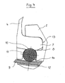
- Spring element 9 abuts.
- the locking body 11 is movably guided in the third recess 14, wherein on the locking body 11 by means of the spring element 9 in the direction of the punch insert 4, a steady pressure force is exerted.
- the spring element 9 is formed in particular as a flat band steel spring and arranged in a provided in the punch body 2 below the third recess 14 recess 12, wherein the spring element 9 presses the locking body 11 in the locking recess 10 in the locking position.
- the spring element 9 is held in the recess 12 and secured against lateral slipping.
- the recess 12 is wider than the thickness of the spring element 9. Zur Holder of the punch body 2, a through hole, not shown, is provided for a retaining pin.
- the invention is not limited to the illustrated embodiment, but is often variable within the scope of the disclosure, in particular in the embodiment of the latching connection 10, 11.
- the stamp according to the invention is for attaching labels, contours or imprints on a variety of materials, preferably in the so-called or gravure printing, but its use is not limited to these methods.
Landscapes
- Labeling Devices (AREA)
- Perforating, Stamping-Out Or Severing By Means Other Than Cutting (AREA)
- Shaping Metal By Deep-Drawing, Or The Like (AREA)
Claims (8)
- Tampon doté d'une pièce de marquage intégrée remplaçable en vue de porter des inscriptions, des motifs ou des empreintes sur des matériaux les plus divers, comprenant un corps (2) muni d'un évidement (5) pour l'essentiel semi-circulaire, dans lequel peut être insérée une pièce de marquage intégrée (4) pourvue de profils de marquage (4'), ladite pièce de marquage intégrée (4) présentant, sur son pourtour extérieur (6) de réalisation semi-circulaire, une saillie d'encliquetage (7) qui peut être introduite par pivotement dans un évidement supplémentaire (8) du corps (2) du tampon, est en applique, dans une position intégrée de consigne dans ledit corps (2) du tampon, contre une butée (13) située dans ledit évidement supplémentaire (8), et est retenue au moyen d'une liaison par déclic, ladite saillie d'encliquetage (7) de ladite pièce de marquage intégrée (4) étant munie, à cette fin, d'une cuvette de crantage (10) dans laquelle pénètre un corps encliquetable (11),
caractérisé par le fait
que le corps encliquetable (11) est logé dans un troisième évidement (14) du corps (2) du tampon, dans lequel il est guidé avec mobilité, le guidage mobile dudit corps encliquetable (11) étant orienté en direction de la pièce de marquage intégrée (4), ledit corps étant pressé en direction de ladite pièce de marquage intégrée (4), par un accumulateur de force prévu dans une cavité (12) pratiquée dans ledit corps (2) du tampon, de façon telle que ladite pièce de marquage intégrée (4) soit retenue de manière imperdable en un emplacement extrême, en position intégrée de consigne dans ledit corps (2) du tampon, et soit arrêtée au moyen de la liaison par déclic (10, 11), sachant qu'une force appliquée à la pièce de marquage intégrée (4) permet de dissocier ladite liaison par déclic (10, 11) et de faire en sorte que ladite pièce de marquage intégrée (4) quitte de nouveau ledit emplacement extrême, par désencliquetage, après une rotation rétrograde hors de l'évidement semi-circulaire (5) dudit corps (2) du tampon. - Tampon selon la revendication 1,
caractérisé par le fait
que la liaison par déclic est constituée du corps encliquetable (11) pénétrant dans la cuvette de crantage (10) de la pièce de marquage intégrée (4) remplaçable, ledit corps encliquetable (11) étant maintenu dans une position crantée, sous l'action d'un élément élastique (9), en applique dans ladite cuvette de crantage (10) de ladite pièce de marquage intégrée (4). - Tampon selon la revendication 1 ou 2,
caractérisé par le fait
que le corps encliquetable (11) est réalisé, de préférence, sous la forme d'une cheville cylindrique dont la surface du cylindre est en applique, dans la position crantée, dans la cuvette de crantage (10) et contre les surfaces latérales de l'évidement (14), ainsi que contre l'élément élastique (9). - Tampon selon l'une des revendications 1, 2 ou 3,
caractérisé par le fait
que le corps encliquetable (11) est guidé avec mobilité, dans l'évidement (14), de façon telle qu'une force de pression continue agisse sur ledit corps encliquetable (11) au moyen de l'élément élastique (9), en direction de la pièce de marquage intégrée (4). - Tampon selon l'une des revendications 2, 3 ou 4,
caractérisé par le fait
que l'élément élastique (9) est réalisé, en particulier, sous la forme d'un ruban élastique aplati en acier et est logé dans une cavité (12) prévue dans le corps (2) dudit tampon, au-dessous de l'évidement (14) dédié au corps encliquetable (11), ledit élément élastique (9) étant en applique contre ledit corps encliquetable (11), la largeur de ladite cavité (12) étant supérieure à l'épaisseur dudit élément élastique (9), afin d'autoriser le nécessaire mouvement dudit élément élastique (9). - Tampon selon l'une des revendications 2, 3, 4 ou 5,
caractérisé par le fait
que l'élément élastique (9) est retenu dans la cavité (12) et est arrêté à l'encontre d'un ripage latéral. - Tampon selon l'une des revendications 1 à 6,
caractérisé par le fait
que la pièce de marquage intégrée (4) peut tourner dans le sens antihoraire autour d'un axe de rotation, en vue de l'insertion de ladite pièce de marquage intégrée (4) dans l'évidement semi-circulaire (5) du corps (2) dudit tampon, sachant que la saillie d'encliquetage (7) de ladite pièce de marquage intégrée (4) peut être introduite dans l'évidement (8) dudit corps (2) du tampon par pivotement vers un emplacement extrême, jusqu'à une butée (13), et est retenue en cet emplacement extrême au moyen de la liaison par déclic (10, 11). - Tampon selon l'une des revendications 1 à 7,
caractérisé par le fait
qu'une force est appliquée manuellement à la pièce de marquage intégrée (4) en vue d'extraire ladite pièce de marquage intégrée (4) hors du corps (2) dudit tampon, sachant que le corps encliquetable (11) se désencliquette de la cuvette de crantage (10) et que ladite pièce de marquage intégrée (4) peut tourner dans le sens horaire, autour de son axe de rotation, jusqu'à ce que la saillie d'encliquetage (7) de ladite pièce de marquage intégrée (4) ne s'engage plus dans l'évidement (8) dudit corps (2) du tampon, et que ladite pièce de marquage intégrée (4) puisse être extraite dudit corps (2) du tampon.
Applications Claiming Priority (1)
| Application Number | Priority Date | Filing Date | Title |
|---|---|---|---|
| DE200820005762 DE202008005762U1 (de) | 2008-04-25 | 2008-04-25 | Stempel mit auswechselbarem Stempeleinsatz |
Publications (3)
| Publication Number | Publication Date |
|---|---|
| EP2111996A2 EP2111996A2 (fr) | 2009-10-28 |
| EP2111996A3 EP2111996A3 (fr) | 2011-05-25 |
| EP2111996B1 true EP2111996B1 (fr) | 2013-02-20 |
Family
ID=39587838
Family Applications (1)
| Application Number | Title | Priority Date | Filing Date |
|---|---|---|---|
| EP20090005612 Active EP2111996B1 (fr) | 2008-04-25 | 2009-04-22 | Tampon doté d'un insert de tampon échangeable |
Country Status (2)
| Country | Link |
|---|---|
| EP (1) | EP2111996B1 (fr) |
| DE (1) | DE202008005762U1 (fr) |
Family Cites Families (3)
| Publication number | Priority date | Publication date | Assignee | Title |
|---|---|---|---|---|
| US5778774A (en) * | 1996-12-18 | 1998-07-14 | Framatome Connectors Usa Inc. | Articulating embossing die |
| DE20307129U1 (de) | 2003-04-27 | 2003-08-14 | Ziegler Sven | Stempel |
| DE202007005512U1 (de) | 2007-04-05 | 2007-07-12 | Ziegler, Sven | Stempel mit auswechselbarem Stempeleinsatz |
-
2008
- 2008-04-25 DE DE200820005762 patent/DE202008005762U1/de not_active Expired - Lifetime
-
2009
- 2009-04-22 EP EP20090005612 patent/EP2111996B1/fr active Active
Also Published As
| Publication number | Publication date |
|---|---|
| EP2111996A2 (fr) | 2009-10-28 |
| DE202008005762U1 (de) | 2008-07-03 |
| EP2111996A3 (fr) | 2011-05-25 |
Similar Documents
| Publication | Publication Date | Title |
|---|---|---|
| EP3307546B1 (fr) | Timbre, tampon encreur et capuchon de fermeture | |
| EP3498484B1 (fr) | Tampon | |
| EP3489024B1 (fr) | Tampon, en particulier tampon de trepied | |
| EP2445696B1 (fr) | Tampon de marquage variable | |
| DE1929875C3 (de) | Haltevorrichtung fur em in einem Formwerkzeug auswechselbar ange ordnetes Formwandteil | |
| EP2111996B1 (fr) | Tampon doté d'un insert de tampon échangeable | |
| AT520700A1 (de) | Transportabler Stempel | |
| EP0476362A2 (fr) | Instrument pour écrire | |
| DE19705187A1 (de) | Datumsstempel für Preß- oder Formwerkzeuge | |
| DE102010024037A1 (de) | Vereinfachter Wechselmarkierungsstempel | |
| DE3129843C2 (de) | Meßband mit einem Beschlag für Innen- und Außenmessung | |
| DE202007005512U1 (de) | Stempel mit auswechselbarem Stempeleinsatz | |
| EP1473169A2 (fr) | Corps de timbrage interchangeable | |
| AT520674A1 (de) | Tragbarer Stempel | |
| DE102012015778A1 (de) | Wischblatt für eine Scheibenwischanlage eines Fahrzeugs und Verbindungsanordnung | |
| DE202011001975U1 (de) | Auftraggerät für eine Flüssigkeit | |
| DE1461636C (de) | Verschlußeinrichtung fur das Vorder ende eines eine zuruckziehbare Federspitze aufweisenden Füllfederhalters | |
| DE4302580C2 (de) | Schreib-, Zeichen- oder Malgerät mit einem Klipp sowie Verfahren zur Montage und Befestigung des Klipps | |
| DE102004030011B3 (de) | Befestigungseinrichtung zum genau positionierten Befestigen eines Prägestempels an einem Lochkörper | |
| DE9005361U1 (de) | Betätigungsvorrichtung | |
| EP2099103B1 (fr) | Pince de sertissage | |
| DE2628740C3 (de) | Pfeifenstopfer | |
| DE3390154T1 (de) | Vorrichtung zum verschiebbaren und drehbaren Anbringen einer Rolle an einer Achse | |
| DE202009008621U1 (de) | Kennzeichnungsstempel | |
| DE1941722U (de) | Vorrichtung zur kennzeichnung von gegenstaenden, insbesondere zur klartextmarkierung von werkstuecken, beispielsweise der weiterverarbeitung dienende halbfabrikate. |
Legal Events
| Date | Code | Title | Description |
|---|---|---|---|
| PUAI | Public reference made under article 153(3) epc to a published international application that has entered the european phase |
Free format text: ORIGINAL CODE: 0009012 |
|
| AK | Designated contracting states |
Kind code of ref document: A2 Designated state(s): AT BE BG CH CY CZ DE DK EE ES FI FR GB GR HR HU IE IS IT LI LT LU LV MC MK MT NL NO PL PT RO SE SI SK TR |
|
| PUAL | Search report despatched |
Free format text: ORIGINAL CODE: 0009013 |
|
| AK | Designated contracting states |
Kind code of ref document: A3 Designated state(s): AT BE BG CH CY CZ DE DK EE ES FI FR GB GR HR HU IE IS IT LI LT LU LV MC MK MT NL NO PL PT RO SE SI SK TR |
|
| AX | Request for extension of the european patent |
Extension state: AL BA RS |
|
| 17P | Request for examination filed |
Effective date: 20111125 |
|
| 17Q | First examination report despatched |
Effective date: 20120123 |
|
| RIC1 | Information provided on ipc code assigned before grant |
Ipc: B41K 1/04 20060101AFI20120814BHEP Ipc: B44B 5/02 20060101ALI20120814BHEP |
|
| GRAP | Despatch of communication of intention to grant a patent |
Free format text: ORIGINAL CODE: EPIDOSNIGR1 |
|
| GRAS | Grant fee paid |
Free format text: ORIGINAL CODE: EPIDOSNIGR3 |
|
| GRAA | (expected) grant |
Free format text: ORIGINAL CODE: 0009210 |
|
| AK | Designated contracting states |
Kind code of ref document: B1 Designated state(s): AT BE BG CH CY CZ DE DK EE ES FI FR GB GR HR HU IE IS IT LI LT LU LV MC MK MT NL NO PL PT RO SE SI SK TR |
|
| REG | Reference to a national code |
Ref country code: GB Ref legal event code: FG4D Free format text: NOT ENGLISH |
|
| REG | Reference to a national code |
Ref country code: CH Ref legal event code: EP |
|
| REG | Reference to a national code |
Ref country code: AT Ref legal event code: REF Ref document number: 597364 Country of ref document: AT Kind code of ref document: T Effective date: 20130315 |
|
| REG | Reference to a national code |
Ref country code: IE Ref legal event code: FG4D Free format text: LANGUAGE OF EP DOCUMENT: GERMAN |
|
| REG | Reference to a national code |
Ref country code: CH Ref legal event code: NV Representative=s name: ROTTMANN, ZIMMERMANN + PARTNER AG, CH |
|
| REG | Reference to a national code |
Ref country code: DE Ref legal event code: R096 Ref document number: 502009006260 Country of ref document: DE Effective date: 20130418 |
|
| REG | Reference to a national code |
Ref country code: NL Ref legal event code: VDEP Effective date: 20130220 |
|
| REG | Reference to a national code |
Ref country code: LT Ref legal event code: MG4D |
|
| PG25 | Lapsed in a contracting state [announced via postgrant information from national office to epo] |
Ref country code: NO Free format text: LAPSE BECAUSE OF FAILURE TO SUBMIT A TRANSLATION OF THE DESCRIPTION OR TO PAY THE FEE WITHIN THE PRESCRIBED TIME-LIMIT Effective date: 20130520 Ref country code: LT Free format text: LAPSE BECAUSE OF FAILURE TO SUBMIT A TRANSLATION OF THE DESCRIPTION OR TO PAY THE FEE WITHIN THE PRESCRIBED TIME-LIMIT Effective date: 20130220 Ref country code: SE Free format text: LAPSE BECAUSE OF FAILURE TO SUBMIT A TRANSLATION OF THE DESCRIPTION OR TO PAY THE FEE WITHIN THE PRESCRIBED TIME-LIMIT Effective date: 20130220 Ref country code: ES Free format text: LAPSE BECAUSE OF FAILURE TO SUBMIT A TRANSLATION OF THE DESCRIPTION OR TO PAY THE FEE WITHIN THE PRESCRIBED TIME-LIMIT Effective date: 20130531 Ref country code: BG Free format text: LAPSE BECAUSE OF FAILURE TO SUBMIT A TRANSLATION OF THE DESCRIPTION OR TO PAY THE FEE WITHIN THE PRESCRIBED TIME-LIMIT Effective date: 20130520 Ref country code: IS Free format text: LAPSE BECAUSE OF FAILURE TO SUBMIT A TRANSLATION OF THE DESCRIPTION OR TO PAY THE FEE WITHIN THE PRESCRIBED TIME-LIMIT Effective date: 20130620 |
|
| PG25 | Lapsed in a contracting state [announced via postgrant information from national office to epo] |
Ref country code: FI Free format text: LAPSE BECAUSE OF FAILURE TO SUBMIT A TRANSLATION OF THE DESCRIPTION OR TO PAY THE FEE WITHIN THE PRESCRIBED TIME-LIMIT Effective date: 20130220 Ref country code: GR Free format text: LAPSE BECAUSE OF FAILURE TO SUBMIT A TRANSLATION OF THE DESCRIPTION OR TO PAY THE FEE WITHIN THE PRESCRIBED TIME-LIMIT Effective date: 20130521 Ref country code: LV Free format text: LAPSE BECAUSE OF FAILURE TO SUBMIT A TRANSLATION OF THE DESCRIPTION OR TO PAY THE FEE WITHIN THE PRESCRIBED TIME-LIMIT Effective date: 20130220 Ref country code: PL Free format text: LAPSE BECAUSE OF FAILURE TO SUBMIT A TRANSLATION OF THE DESCRIPTION OR TO PAY THE FEE WITHIN THE PRESCRIBED TIME-LIMIT Effective date: 20130220 Ref country code: SI Free format text: LAPSE BECAUSE OF FAILURE TO SUBMIT A TRANSLATION OF THE DESCRIPTION OR TO PAY THE FEE WITHIN THE PRESCRIBED TIME-LIMIT Effective date: 20130220 Ref country code: PT Free format text: LAPSE BECAUSE OF FAILURE TO SUBMIT A TRANSLATION OF THE DESCRIPTION OR TO PAY THE FEE WITHIN THE PRESCRIBED TIME-LIMIT Effective date: 20130620 |
|
| PG25 | Lapsed in a contracting state [announced via postgrant information from national office to epo] |
Ref country code: HR Free format text: LAPSE BECAUSE OF FAILURE TO SUBMIT A TRANSLATION OF THE DESCRIPTION OR TO PAY THE FEE WITHIN THE PRESCRIBED TIME-LIMIT Effective date: 20130220 |
|
| BERE | Be: lapsed |
Owner name: ZIEGLER, SVEN Effective date: 20130430 |
|
| PG25 | Lapsed in a contracting state [announced via postgrant information from national office to epo] |
Ref country code: DK Free format text: LAPSE BECAUSE OF FAILURE TO SUBMIT A TRANSLATION OF THE DESCRIPTION OR TO PAY THE FEE WITHIN THE PRESCRIBED TIME-LIMIT Effective date: 20130220 Ref country code: SK Free format text: LAPSE BECAUSE OF FAILURE TO SUBMIT A TRANSLATION OF THE DESCRIPTION OR TO PAY THE FEE WITHIN THE PRESCRIBED TIME-LIMIT Effective date: 20130220 Ref country code: RO Free format text: LAPSE BECAUSE OF FAILURE TO SUBMIT A TRANSLATION OF THE DESCRIPTION OR TO PAY THE FEE WITHIN THE PRESCRIBED TIME-LIMIT Effective date: 20130220 Ref country code: EE Free format text: LAPSE BECAUSE OF FAILURE TO SUBMIT A TRANSLATION OF THE DESCRIPTION OR TO PAY THE FEE WITHIN THE PRESCRIBED TIME-LIMIT Effective date: 20130220 Ref country code: NL Free format text: LAPSE BECAUSE OF FAILURE TO SUBMIT A TRANSLATION OF THE DESCRIPTION OR TO PAY THE FEE WITHIN THE PRESCRIBED TIME-LIMIT Effective date: 20130220 Ref country code: CZ Free format text: LAPSE BECAUSE OF FAILURE TO SUBMIT A TRANSLATION OF THE DESCRIPTION OR TO PAY THE FEE WITHIN THE PRESCRIBED TIME-LIMIT Effective date: 20130220 |
|
| PG25 | Lapsed in a contracting state [announced via postgrant information from national office to epo] |
Ref country code: MC Free format text: LAPSE BECAUSE OF FAILURE TO SUBMIT A TRANSLATION OF THE DESCRIPTION OR TO PAY THE FEE WITHIN THE PRESCRIBED TIME-LIMIT Effective date: 20130220 Ref country code: CY Free format text: LAPSE BECAUSE OF FAILURE TO SUBMIT A TRANSLATION OF THE DESCRIPTION OR TO PAY THE FEE WITHIN THE PRESCRIBED TIME-LIMIT Effective date: 20130220 |
|
| PLBE | No opposition filed within time limit |
Free format text: ORIGINAL CODE: 0009261 |
|
| STAA | Information on the status of an ep patent application or granted ep patent |
Free format text: STATUS: NO OPPOSITION FILED WITHIN TIME LIMIT |
|
| PG25 | Lapsed in a contracting state [announced via postgrant information from national office to epo] |
Ref country code: IT Free format text: LAPSE BECAUSE OF FAILURE TO SUBMIT A TRANSLATION OF THE DESCRIPTION OR TO PAY THE FEE WITHIN THE PRESCRIBED TIME-LIMIT Effective date: 20130220 |
|
| 26N | No opposition filed |
Effective date: 20131121 |
|
| GBPC | Gb: european patent ceased through non-payment of renewal fee |
Effective date: 20130520 |
|
| REG | Reference to a national code |
Ref country code: IE Ref legal event code: MM4A |
|
| PG25 | Lapsed in a contracting state [announced via postgrant information from national office to epo] |
Ref country code: BE Free format text: LAPSE BECAUSE OF NON-PAYMENT OF DUE FEES Effective date: 20130430 |
|
| REG | Reference to a national code |
Ref country code: FR Ref legal event code: ST Effective date: 20131231 |
|
| PG25 | Lapsed in a contracting state [announced via postgrant information from national office to epo] |
Ref country code: FR Free format text: LAPSE BECAUSE OF NON-PAYMENT OF DUE FEES Effective date: 20130430 |
|
| REG | Reference to a national code |
Ref country code: DE Ref legal event code: R097 Ref document number: 502009006260 Country of ref document: DE Effective date: 20131121 |
|
| PG25 | Lapsed in a contracting state [announced via postgrant information from national office to epo] |
Ref country code: IE Free format text: LAPSE BECAUSE OF NON-PAYMENT OF DUE FEES Effective date: 20130422 Ref country code: GB Free format text: LAPSE BECAUSE OF NON-PAYMENT OF DUE FEES Effective date: 20130520 |
|
| PG25 | Lapsed in a contracting state [announced via postgrant information from national office to epo] |
Ref country code: MT Free format text: LAPSE BECAUSE OF FAILURE TO SUBMIT A TRANSLATION OF THE DESCRIPTION OR TO PAY THE FEE WITHIN THE PRESCRIBED TIME-LIMIT Effective date: 20130220 |
|
| REG | Reference to a national code |
Ref country code: DE Ref legal event code: R082 Ref document number: 502009006260 Country of ref document: DE Representative=s name: KANZLEI "REGION GOEPPINGEN" (GBR) PATENTANWALT, DE Ref country code: DE Ref legal event code: R082 Ref document number: 502009006260 Country of ref document: DE Representative=s name: FUERST, SIEGFRIED, DIPL.-ING., DE |
|
| PG25 | Lapsed in a contracting state [announced via postgrant information from national office to epo] |
Ref country code: TR Free format text: LAPSE BECAUSE OF FAILURE TO SUBMIT A TRANSLATION OF THE DESCRIPTION OR TO PAY THE FEE WITHIN THE PRESCRIBED TIME-LIMIT Effective date: 20130220 |
|
| PG25 | Lapsed in a contracting state [announced via postgrant information from national office to epo] |
Ref country code: MK Free format text: LAPSE BECAUSE OF FAILURE TO SUBMIT A TRANSLATION OF THE DESCRIPTION OR TO PAY THE FEE WITHIN THE PRESCRIBED TIME-LIMIT Effective date: 20130220 Ref country code: LU Free format text: LAPSE BECAUSE OF NON-PAYMENT OF DUE FEES Effective date: 20130422 Ref country code: HU Free format text: LAPSE BECAUSE OF FAILURE TO SUBMIT A TRANSLATION OF THE DESCRIPTION OR TO PAY THE FEE WITHIN THE PRESCRIBED TIME-LIMIT; INVALID AB INITIO Effective date: 20090422 |
|
| REG | Reference to a national code |
Ref country code: CH Ref legal event code: PCAR Free format text: NEW ADDRESS: GARTENSTRASSE 28 A, 5400 BADEN (CH) |
|
| REG | Reference to a national code |
Ref country code: DE Ref legal event code: R082 Ref document number: 502009006260 Country of ref document: DE Representative=s name: FUERST, SIEGFRIED, DIPL.-ING., DE |
|
| PGFP | Annual fee paid to national office [announced via postgrant information from national office to epo] |
Ref country code: CH Payment date: 20190328 Year of fee payment: 11 |
|
| REG | Reference to a national code |
Ref country code: CH Ref legal event code: PL |
|
| PG25 | Lapsed in a contracting state [announced via postgrant information from national office to epo] |
Ref country code: CH Free format text: LAPSE BECAUSE OF NON-PAYMENT OF DUE FEES Effective date: 20200430 Ref country code: LI Free format text: LAPSE BECAUSE OF NON-PAYMENT OF DUE FEES Effective date: 20200430 |
|
| PGFP | Annual fee paid to national office [announced via postgrant information from national office to epo] |
Ref country code: DE Payment date: 20250425 Year of fee payment: 17 |
|
| PGFP | Annual fee paid to national office [announced via postgrant information from national office to epo] |
Ref country code: AT Payment date: 20250401 Year of fee payment: 17 |