EP2112360B1 - Bloc monolithique et dispositif de commande des soupapes pour moteur à quatre temps - Google Patents
Bloc monolithique et dispositif de commande des soupapes pour moteur à quatre temps Download PDFInfo
- Publication number
- EP2112360B1 EP2112360B1 EP09251153A EP09251153A EP2112360B1 EP 2112360 B1 EP2112360 B1 EP 2112360B1 EP 09251153 A EP09251153 A EP 09251153A EP 09251153 A EP09251153 A EP 09251153A EP 2112360 B1 EP2112360 B1 EP 2112360B1
- Authority
- EP
- European Patent Office
- Prior art keywords
- cylinder
- crank
- crankcase
- exhaust
- Prior art date
- Legal status (The legal status is an assumption and is not a legal conclusion. Google has not performed a legal analysis and makes no representation as to the accuracy of the status listed.)
- Not-in-force
Links
- 238000005266 casting Methods 0.000 claims description 9
- 239000000446 fuel Substances 0.000 claims description 8
- 238000004519 manufacturing process Methods 0.000 claims description 2
- 238000000034 method Methods 0.000 claims 1
- 238000002485 combustion reaction Methods 0.000 description 9
- 239000003921 oil Substances 0.000 description 9
- 239000010687 lubricating oil Substances 0.000 description 5
- 238000001816 cooling Methods 0.000 description 4
- 239000003595 mist Substances 0.000 description 4
- 239000003999 initiator Substances 0.000 description 3
- 229910000838 Al alloy Inorganic materials 0.000 description 2
- XEEYBQQBJWHFJM-UHFFFAOYSA-N Iron Chemical compound [Fe] XEEYBQQBJWHFJM-UHFFFAOYSA-N 0.000 description 2
- 230000005540 biological transmission Effects 0.000 description 2
- 239000000463 material Substances 0.000 description 2
- 229910052751 metal Inorganic materials 0.000 description 2
- 239000002184 metal Substances 0.000 description 2
- 238000007789 sealing Methods 0.000 description 2
- 239000004215 Carbon black (E152) Substances 0.000 description 1
- VYZAMTAEIAYCRO-UHFFFAOYSA-N Chromium Chemical compound [Cr] VYZAMTAEIAYCRO-UHFFFAOYSA-N 0.000 description 1
- 241000755266 Kathetostoma giganteum Species 0.000 description 1
- FYYHWMGAXLPEAU-UHFFFAOYSA-N Magnesium Chemical compound [Mg] FYYHWMGAXLPEAU-UHFFFAOYSA-N 0.000 description 1
- 229910000831 Steel Inorganic materials 0.000 description 1
- CSDREXVUYHZDNP-UHFFFAOYSA-N alumanylidynesilicon Chemical compound [Al].[Si] CSDREXVUYHZDNP-UHFFFAOYSA-N 0.000 description 1
- 229910052782 aluminium Inorganic materials 0.000 description 1
- XAGFODPZIPBFFR-UHFFFAOYSA-N aluminium Chemical compound [Al] XAGFODPZIPBFFR-UHFFFAOYSA-N 0.000 description 1
- 230000000712 assembly Effects 0.000 description 1
- 238000000429 assembly Methods 0.000 description 1
- 229910052804 chromium Inorganic materials 0.000 description 1
- 239000011651 chromium Substances 0.000 description 1
- 238000005516 engineering process Methods 0.000 description 1
- 230000007613 environmental effect Effects 0.000 description 1
- 229930195733 hydrocarbon Natural products 0.000 description 1
- 150000002430 hydrocarbons Chemical class 0.000 description 1
- 238000001746 injection moulding Methods 0.000 description 1
- 229910052742 iron Inorganic materials 0.000 description 1
- 229910052749 magnesium Inorganic materials 0.000 description 1
- 239000011777 magnesium Substances 0.000 description 1
- 238000012986 modification Methods 0.000 description 1
- 230000004048 modification Effects 0.000 description 1
- MOFOBJHOKRNACT-UHFFFAOYSA-N nickel silver Chemical compound [Ni].[Ag] MOFOBJHOKRNACT-UHFFFAOYSA-N 0.000 description 1
- 239000010956 nickel silver Substances 0.000 description 1
- 230000002000 scavenging effect Effects 0.000 description 1
- 239000010959 steel Substances 0.000 description 1
- 239000011800 void material Substances 0.000 description 1
Images


Classifications
-
- F—MECHANICAL ENGINEERING; LIGHTING; HEATING; WEAPONS; BLASTING
- F02—COMBUSTION ENGINES; HOT-GAS OR COMBUSTION-PRODUCT ENGINE PLANTS
- F02F—CYLINDERS, PISTONS OR CASINGS, FOR COMBUSTION ENGINES; ARRANGEMENTS OF SEALINGS IN COMBUSTION ENGINES
- F02F1/00—Cylinders; Cylinder heads
- F02F1/002—Integrally formed cylinders and cylinder heads
-
- F—MECHANICAL ENGINEERING; LIGHTING; HEATING; WEAPONS; BLASTING
- F01—MACHINES OR ENGINES IN GENERAL; ENGINE PLANTS IN GENERAL; STEAM ENGINES
- F01L—CYCLICALLY OPERATING VALVES FOR MACHINES OR ENGINES
- F01L1/00—Valve-gear or valve arrangements, e.g. lift-valve gear
- F01L1/02—Valve drive
-
- F—MECHANICAL ENGINEERING; LIGHTING; HEATING; WEAPONS; BLASTING
- F01—MACHINES OR ENGINES IN GENERAL; ENGINE PLANTS IN GENERAL; STEAM ENGINES
- F01L—CYCLICALLY OPERATING VALVES FOR MACHINES OR ENGINES
- F01L1/00—Valve-gear or valve arrangements, e.g. lift-valve gear
- F01L1/02—Valve drive
- F01L1/024—Belt drive
-
- F—MECHANICAL ENGINEERING; LIGHTING; HEATING; WEAPONS; BLASTING
- F01—MACHINES OR ENGINES IN GENERAL; ENGINE PLANTS IN GENERAL; STEAM ENGINES
- F01L—CYCLICALLY OPERATING VALVES FOR MACHINES OR ENGINES
- F01L1/00—Valve-gear or valve arrangements, e.g. lift-valve gear
- F01L1/02—Valve drive
- F01L1/04—Valve drive by means of cams, camshafts, cam discs, eccentrics or the like
- F01L1/047—Camshafts
-
- F—MECHANICAL ENGINEERING; LIGHTING; HEATING; WEAPONS; BLASTING
- F01—MACHINES OR ENGINES IN GENERAL; ENGINE PLANTS IN GENERAL; STEAM ENGINES
- F01L—CYCLICALLY OPERATING VALVES FOR MACHINES OR ENGINES
- F01L1/00—Valve-gear or valve arrangements, e.g. lift-valve gear
- F01L1/12—Transmitting gear between valve drive and valve
- F01L1/18—Rocking arms or levers
-
- F—MECHANICAL ENGINEERING; LIGHTING; HEATING; WEAPONS; BLASTING
- F02—COMBUSTION ENGINES; HOT-GAS OR COMBUSTION-PRODUCT ENGINE PLANTS
- F02F—CYLINDERS, PISTONS OR CASINGS, FOR COMBUSTION ENGINES; ARRANGEMENTS OF SEALINGS IN COMBUSTION ENGINES
- F02F7/00—Casings, e.g. crankcases
- F02F7/0002—Cylinder arrangements
- F02F7/0004—Crankcases of one-cylinder engines
-
- F—MECHANICAL ENGINEERING; LIGHTING; HEATING; WEAPONS; BLASTING
- F02—COMBUSTION ENGINES; HOT-GAS OR COMBUSTION-PRODUCT ENGINE PLANTS
- F02B—INTERNAL-COMBUSTION PISTON ENGINES; COMBUSTION ENGINES IN GENERAL
- F02B75/00—Other engines
- F02B75/02—Engines characterised by their cycles, e.g. six-stroke
- F02B2075/022—Engines characterised by their cycles, e.g. six-stroke having less than six strokes per cycle
- F02B2075/027—Engines characterised by their cycles, e.g. six-stroke having less than six strokes per cycle four
-
- Y—GENERAL TAGGING OF NEW TECHNOLOGICAL DEVELOPMENTS; GENERAL TAGGING OF CROSS-SECTIONAL TECHNOLOGIES SPANNING OVER SEVERAL SECTIONS OF THE IPC; TECHNICAL SUBJECTS COVERED BY FORMER USPC CROSS-REFERENCE ART COLLECTIONS [XRACs] AND DIGESTS
- Y10—TECHNICAL SUBJECTS COVERED BY FORMER USPC
- Y10T—TECHNICAL SUBJECTS COVERED BY FORMER US CLASSIFICATION
- Y10T29/00—Metal working
- Y10T29/49—Method of mechanical manufacture
- Y10T29/49229—Prime mover or fluid pump making
- Y10T29/4927—Cylinder, cylinder head or engine valve sleeve making
Definitions
- the present invention relates generally to internal combustion engines, and, in particular, to cylinder crankcase assemblies for four-stroke engines.
- Both two and four-stroke engines typically consist of a crankcase, cylinder block, and cylinder head.
- the crankcase, cylinder block, and cylinder head need to be joined together using mechanical fasteners, thereby necessitating both additional fasteners and precisely machined fastener holes.
- Engines composed of separate cylinder blocks, cylinder heads, and crankcases also require sealing gaskets. These additional components add extra weight to the engines and also present greater potential for gasket failures.
- WO99/02824 discloses a power tool having a rotary implement driven by a four cycle engine.
- the engine crankcase is vented via an axial passageway which extends through at least one of the crankshaft and camshaft axial shaft members.
- US4,513,702 discloses an internal combustion engine which comprises an outside member including a cylinder block section and a crankcase half section which are both casted into a single body, and a crankcase half having a corresponding opening edge thereon for covering the opening of the crankcase half section.
- WO2004/083614A1 discloses a four-stroke reciprocating piston internal combustion engine with an intake valve an exhaust valve and a valve drive assembly driven by the crankshaft for actuating the intake valve and the exhaust valve.
- DE19860391A1 discloses a chain saw which comprises a short-stroke IC engine with a stroke/bore ratio of less than 0.8.
- JP2002-89211A discloses a valve system of a four-cycle engine time in which a governing transmission gear is mounted at one side of an engine body and a cam device comprises a cam connected to a driven pulley of the time governing transmission gear at one side of the cylinder head.
- US2001/0015182A1 discloses a single cylinder, internal combustion engine which comprises an engine housing in which the overhead camshaft and crankshaft are rotatably supported, and the housing includes an integrally formed cylinder and head.
- a timing belt disposed externally of the engine housing interconnects the crankshaft and camshaft.
- JP06-185407 discloses an internal combustion engine in which an opening is provided across the total area from the full face on the opposite side of an output shaft in a crank chamber to the full bottom face on the opposite side of a cylinder hole.
- the invention provides a monolithic four-stroke crankcase, cylinder block, and cylinder head (monolithic four-stroke cylinder crankcase) is provided.
- the monolithic four-stroke cylinder crankcase may include the use of a half-crank crankshaft with a dry-type belt and overhead valves.
- One advantage is that the half-crank crankshaft reduces both the weight and size of the cylinder crankcase. Additional details and advantages are described below.
- the invention may include any of the following aspects in various combinations and may also include any other aspect described below in the written description or shown in the attached drawings.
- One aspect of the present invention includes a four-stroke engine having a cylinder crankcase comprising: a monolithic cylinder head, a cylinder block having a cylinder, and a crankcase that comprises a crank pocket; a piston for reciprocating in the cylinder; a connecting rod; a half-crank crankshaft in the crankcase, wherein the piston is connected to the crankshaft by the connecting rod; an intake valve in the cylinder head and configured to open and close a fuel intake into the cylinder; an exhaust valve in the cylinder head and configured to open and close an exhaust outlet from the cylinder, a camshaft configured to actuate the intake valve and the exhaust valve; and a belt connecting the crankshaft and the camshaft; an inner bearing in the crank pocket configured to support the crankshaft; an outer bearing in the crank pocket configured to support the crankshaft; and a pocket between the inner bearing and the outer bearing; wherein the belt rotates within the pocket and the pocket through which the belt runs is a cast feature formed simultaneously with the casting of the crankcase;
- Another aspect of the present invention includes a method of making a four-stroke cylinder crankcase comprising: constructing a cylinder head, a cylinder, and a crankcase as a single monolithic piece, and wherein the crankcase comprises a crank pocket and the crank pocket further comprises an inner bearing and an outer bearing configured to support the crankshaft; the crank pocket further comprising a pocket between the inner bearing and the outer bearing, the cylinder crankcase further comprising a piston for reciprocating in the cylinder; a connecting rod; a half-crank crankshaft in the crankcase, wherein the piston is connected to the crankshaft by the connecting rod; an intake valve in the cylinder head and configured to open and close a fuel intake into the cylinder; an exhaust valve in the cylinder head and configured to open and close an exhaust outlet from the cylinder, a camshaft configured to actuate the intake valve and the exhaust valve; and a belt connecting the crankshaft and the camshaft; wherein the belt rotates within the pocket; inserting the half-crank crankshaft into
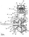
- FIG. 1 presents a profile view of an engine having a monolithic cylinder crankcase 10.
- the monolithic four-stroke cylinder crankcase 10 includes a crankcase 20, cylinder block 50, and cylinder head 80.
- the crankcase 20 includes an integrally cast crank pocket 21 configured to support a crankshaft 22, a plurality of fingers 24 that connect to an outer frame 25, a pocket 26 through which a belt 30 runs, and an outer bearing 28 into which the crankshaft 22 bears.
- the cylinder block 50 includes a plurality of cooling fins 54 and at least one boss 52 for mounting an ignition module.
- the cylinder block 50 also includes a cylinder 51 that generally defines a cylinder axial direction 53 from the crankcase 20 to the cylinder head 80.
- the cylinder head 80 includes a camshaft 82 having a cam gear 84, a valve cover 86, an exhaust passage 86, a fuel passage 90, and a spark plug 92.
- the valve cover 86 which is mechanically fastened to the cylinder head 80, is not of uniform height. Instead, it is taller in a cylinder axial direction at one side than the other. This corresponds to the cylinder head 80 which is shorter at one side than the other.
- the valve cover 86 will be taller on the side with the intake and exhaust valves 98 and 100 to allow greater access to the valves 98 and 100 and valve lashes when the valve cover 86 is removed.
- FIG 2 shows a cross-sectional view of the monolithic four-stroke cylinder crankcase 10 illustrated in Figure 1 .
- the crankshaft 22 is rotatable within an inner bearing 40 and an outer bearing 28. Inside the crank chamber 48. a counterweight 32 is attached to the crankshaft 22.
- a crank pin 36 connects the crankshaft 22 and counterweight 32 to the connecting rod 34.
- the other end of the connecting rod 34 connects to the piston 56 via the connecting pin 60.
- the belt 30 passes into the crank pocket 21 via the pocket 26 formed therein.
- the belt runs around a crank gear 42 mounted on the crankshaft 22 in the pocket 26 before emerging out of the other side of the pocket 26.
- the crankcase 20 is sealed by a crank cover 44 and a sealing gasket 46.
- crankcase 20 and crank cover 44 define a crank chamber 48, which doubles as an oil reservoir.
- an oil slinger 38 Opposite the connecting rod 34 on the crank pin 38 is an oil slinger 38.
- the oil slinger 38 distributes lubricating oil from the crank chamber 48 to the cylinder 51 as the piston 56 reciprocates inside the cylinder 51.
- the cylinder block 50 also includes a passage 58 that connects the valve chamber 106 in the cylinder head 80 to the crank chamber 48, so that lubricating oil may be supplied to and return from the valve chamber 106.
- a check valve may be included in the passage 58 to prevent the valve chamber 106 from being filled with lubricating oil when the engine is operated in an inverted position.
- the cylinder head 80 includes an intake valve seat 94 four an intake valve 98, and an exhaust valve seat 96 for an exhaust valve 100.
- the intake valve 98 is attached to an intake rocker 102, whereas the exhaust valve 100 is attached to an exhaust rocker 104.
- Springs 101 bias the intake rocker 102 and the exhaust rocker 104 to a closed position. Both the intake rocker 102 and exhaust rocker 104 are located in the valve chamber 106, which is defined by the void created between the valve cover 86 and the cylinder head 80.
- FIG 3 illustrates an expanded sectional view of the area surrounding the camshaft 82 and the intake and exhaust rockers 102 and 104.
- the belt 30 connects to the cam gear 84, which is placed on the carn shaft 82.
- the camshaft 82 includes an intake cam lobe 108 and an exhaust cam lobe 110.
- the intake cam lobe 108 pushes against the intake rocker 102 to open the intake valve 98.
- the exhaust cam lobe 110 pushes against the exhaust rocker 104 to open the exhaust valve 100 when the camshaft 82 has completed about three-quarters of a rotation since opening the intake valve 98.
- the bearing 83 for the camshaft 82 is confined entirely within the cylinder head 80, however it should be understood that the camshaft bearing 83 may be located so that it is partially contained in the valve cover 86 and partially in the cylinder head 80. Furthermore, it should be understood that the valve timing may be changed by adjusting the position of the intake and exhaust cam lobes 108 and 110 on the camshaft.
- the reciprocation of the piston 56 in the cylinder 51 drives the balf-crank crankshaft 22 by way of the connecting rod 34.
- a crank gear 42 is mounted on the crankshaft 22 in the pocket 26 in the crank pocket 21 between the inner bearing 40 and the outer bearing 28, The crank gear 42 drives the belt 30.
- the belt 30 drives the cam gear 84.
- the cam gear 84 and the crank gear 82 have a gearing ratio of 1:2 so that for every rotation of the crank gear 82 the cam gear 84 makes one-half of a rotation.
- the intake valve 98 is opened by the intake cam lobe 108 and intake rocker 102, to allow a fresh charge to enter the cylinder 51.
- the intake valve 98 closes and the piston 66 returns on an upstroke, after which the spark plug initiator and spark plug 92 fire causing combustion and a second down stroke of the piston 56.
- the exhaust cam lobe 110 and the exhaust rocker 104 open the exhaust valve 100 and, during the subsequent up-stroke, the piston 56 drives the exhaust from the engine.
- the pocket 26 through which the belt 30 runs is a cast feature formed simultaneous with the casting of the monolithic four-stroke cylinder crankcase 10.
- the crank pocket 21 includes the inner bearing 40 and the outer bearing 28. These bearings 40 and 28 may be pressed into the crank pocket 21 and provide support for the crankshaft 22 and the counterweight 32 to balance the engine.
- the bearing bores 41 and 29 in which the inner bearing 42 and outer bearing 28 are placed are preferable cast; however, the borings may also be machined.
- the cast pocket 26 allows for the use of a half-crank crankshaft 22 with a dry-type belt 30. With a dry-type belt, a belt cover may be used but it is not required.
- using a dry-type belt with a half-crank crankshaft eliminates the need to enlarge the cylinder crankcase casting to form a chamber for the belt in the cylinder block, thereby reducing the weight and cost of the cylinder crankcase.
- the engine is lubricated by the oil slinger 38.
- the slinger 38 located in the crank chamber 48, is rotated so that it dips into and out of a volume of lubricating oil.
- the crank pin 36 rotates about the axis of the crankshaft 22 the oil slinger 38 throws lubricating oil into the cylinder 51.
- the valve chamber includes two passages 58 and 59.
- passage 59 is placed along a central plane 35 defined by the rotation of the connecting rod 34 and opens adjacent to the connecting rod 34 in the crank chamber 48.
- the mist of oil formed by the slinger 38 may pass through the passage 59 into the valve chamber 106. As this mist condenses or collects in the valve chamber 106, it may flow back to the crankcase through one or both of passages 58 and 59.
- one passage 59 connecting the valve chamber 106 and the crank chamber 48 may be used, or more than two passages may be used.
- the oil mist may pass through either passage 58 or 59, and condensed oil may return via either passage.
- the exhaust passage 88 may be placed at an angle to the plane 35 defined by the rotation of the connecting rod 34.
- the exhaust passage 88 allows for the spark plug socket 93 to be placed adjacent to the exhaust passage. With this arrangement, the spark plug 92 may be more easily accessed.
- the spark plug socket 93 and exhaust passage 88 may be used.
- At least one opening is provided between two of the plurality of fingers 24.
- the plurality of fingers 24 connect the crank pocket 21 to the outer frame 25.
- a flywheel 31, shown in Figure 6 connects to the crankshaft 22 adjacent to the outer frame 25.
- the flywheel 31 may include fan elements to help pull cooling air from the side opposite the crankshaft 22, through the at least one opening, around the crankcase 20, about the outer frame 25, and to the cylinder block 50 which includes a plurality of cooling fins 54.
- the monolithic four-stroke cylinder crankcase 10 also includes attachments for various engine components.
- the cylinder head 80 includes a connection 90 for a fuel supply system, which may consist of a carburetor.
- An exhaust outlet 88 that forms a connection for an exhaust pipe or muffler is also supplied.
- at least one boss 52 is provided for connecting a spark plug initiator (not shown) such as an ignition module, It may be desirable to place the boss 52 as dose to the flywheel 31 as possible to allow for better cooling of the spark plug 92 and spark plug initiator.
- the pocket 26 in the crank pocket 21 may include a pair of slots 27.
- the slots 27 are cast into the crank pocket 21.
- the slots 27 provide an opening so that the belt 30 may enter through one slot 27, pass around the crank gear 42, and then exit the pocket 26 through the other slot 27.
- the slots 27 may simplify the casting of the monolithic four-stroke cylinder crankcase 10.
- Figure 5 also shows the bearing 81 for the camshaft 82 in the cylinder head 80. Additionally, the socket 93 for the spark plug is shown adjacent to the exhaust passage 88.
- the camshaft 82 may be placed in the cylinder head 80 in a plane defined by the axis 53 of the cylinder 51 and the axis 23 of the crankshaft 22, as opposed to offset from this plane as in Figures 1-3 .
- the camshaft bearings 83 can be located so that they are contained partially in the cylinder head 83 and partially in the valve cover 86.
- the intake cam lobe 108 and the exhaust cam lobe 110 are formed monolithically with the camshaft 82.
- the cam lobes 108 and 110 need n.ot be monolithically formed as part of the camshaft 82, but could be attached to the camshaft 82.
- an intake cam follower 103 and an exhaust cam follower 105 are used.
- the camshaft 82 is driven by the belt 30 as described above.
- the intake cam lobe 108 depresses the intake cam follower 103, and then after about three-quarters of a revolution of the camshaft 82 the exhaust cam lobe 110 depresses the exhaust cam follower 105.
- the intake valve 98 and exhaust valve 100 are opened and closed at the appropriate times. It should be understood that the valve timing may be changed by adjusting the positions of the cam lobes 108 and 110.
- FIG. 7 and 8 An alternate cylinder crankcase is illustrated in Figures 7 and 8 .
- the monolithic four-stroke cylinder crankcase 10 has an open pocket 26 through which the belt 30 passes.
- the monolithic four-stroke cylinder crankcase has an offset camshaft 82 with only one cam lobe 116.
- the cam lobe 116 activates both the intake rocker arm 112 and the exhaust rocker arm 114.
- Figure 8 shows an isolated view of the cam lobe 116, the intake rocker arm 112, the exhaust rocker arm 114, the intake valve 98, and the exhaust valve 100.
- the Intake rocker arm 112 includes an intake contact clement 120 near the cam lobe 116, while the exhaust rocker arm 114 includes an exhaust contact element 122 near the cam lobe 116.
- the intake rocker arm 112 and the exhaust rocker arm 114 may be made from a variety of materials, for example stamped metal.
- the cam lobe 116 drives either the exhaust rocker arm 114 up, or the intake rocker arm 112 down.
- the intake rocker arm 112 rotates about the rocker pivot pin 118B. This pivoting causes the intake rocker arm 112 to push down and open the intake valve 98.
- this rocker arrangement eliminates one of the cam lobes from a traditional camshaft it should be understood that the valve timing can be changed by adjusting the locations of the intake contact element 120 and exhaust contact element 122 relative to one another and about the circumference of the cam lobe 116.
- the monolithic four-stroke cylinder crankcase described above may be integrally cast as a single nephew.
- the monolithic four-stroke cylinder crankease is made using a die-cast injection molding process.
- other means of casting may be used.
- the monolithic four-stroke cylinder crankcase is made of an aluminum alloy, and more particularly from a high silicon aluminum alloy.
- the monolithic four-stroke cylinder crankcase may be made of any suitable metal able to withstand the elevated combustion temperatures, such as steel, aluminum, iron, or magnesium.
- the cylinder may be plated using, for example, chromium or nickel silver (nickelsil). Alternatively, the cylinder may not be plated but instead the piston may be plated.
Landscapes
- Engineering & Computer Science (AREA)
- Mechanical Engineering (AREA)
- General Engineering & Computer Science (AREA)
- Chemical & Material Sciences (AREA)
- Combustion & Propulsion (AREA)
- Valve-Gear Or Valve Arrangements (AREA)
- Cylinder Crankcases Of Internal Combustion Engines (AREA)
Claims (5)
- Moteur à quatre temps, comportant un carter de cylindre (10), comprenant :une culasse de cylindre monolithique (80), un bloc de cylindre (50) comportant un cylindre (51) et un carter (20) comprenant une poche de manivelle (21) ;un piston (56) pour effectuer un mouvement alternatif dans le cylindre (51) ;une bielle (34) ;un vilebrequin à demi-manivelle (22) dans le carter du moteur (20), le piston (56) étant connecté au vilebrequin (22) par la bielle (34) ;une soupape d'admission (98) dans la culasse (80), configurée de sorte à ouvrir et à fermer une admission de carburant vers le cylindre (51) ;une soupape d'échappement (100) dans la culasse du cylindre (80), configurée de sorte à ouvrir et à fermer un orifice d'échappement (88) à partir du cylindre (51) ;un arbre à cames (82), configuré de sorte à actionner la soupape d'admission (98) et la soupape d'échappement (100) ;une courroie (30), connectant le vilebrequin (22) et l'arbre à cames (82) ;un palier interne (40) dans la poche de manivelle (21), configuré de sorte à supporter le vilebrequin (22) ;un palier externe (28) dans la poche de manivelle (21), configuré de sorte à supporter le vilebrequin (22) ;une poche (26) entre le palier interne (40) et le palier externe (28) ;la courroie (30) tournant dans la poche (26), et la poche (26) à travers laquelle se déplace la courroie (30) étant constituée par une structure coulée formée de manière simultanée à la coulée du carter (20) ; etune partie de la courroie (30) rentrant dans la poche (26) à travers une première fente (27) dans la poche de manivelle (21) pour passer autour du mécanisme à bielle et manivelle (42) monté sur le vilebrequin (22), une autre partie de la courroie (30) sortant de la poche (26) à travers une deuxième fente (27) dans la poche de manivelle (21), les fentes (26, 27) étant coulées dans la poche de manivelle (21).
- Moteur à quatre temps selon la revendication 1, comprenant en outre :un galet de came d'admission (103) fixé sur la soupape d'admission (98) ;un galet de came d'échappement (105) fixé sur la soupape d'échappement (100) ; etun bossage de came d'admission (108) et un bossage de came d'échappement (110) agencés sur l'arbre à cames (82) et configurés de sorte à enfoncer respectivement le galet de came d'admission (103) et le galet de came d'échappement (105) ;le bossage de came d'admission (108) et le bossage de came d'échappement (110) étant formés de manière monolithique avec l'arbre à cames (82).
- Moteur à quatre temps selon la revendication 2, comprenant en outre :un culbuteur d'admission (102) fixé sur la soupape d'admission (98) et un culbuteur d'échappement (104) fixé sur la soupape d'échappement (100) ;le bossage de came d'admission (108) et le bossage de came d'échappement (110) étant configurés de sorte à actionner respectivement le culbuteur d'admission (102) et le culbuteur d'échappement (104).
- Procédé de fabrication d'un moteur à quatre temps, comportant un carter de cylindre (10), comprenant les étapes ci-dessous :construction d'une culasse (80), d'un cylindre (51) et d'un carter (20) sous forme d'une seule pièce monolithique, le carter (20) comprenant une poche de manivelle (21) et la poche de manivelle (21) comprenant en outre un palier interne (40) et un palier externe (28), configurés de sorte à supporter le vilebrequin (22) ; la poche de manivelle (21) comprenant en outre une poche (26) entre le palier interne (40) et le palier externe (28), le carter de cylindre (10) comprenant en outre un piston (56) pour effectuer un mouvement alternatif dans le cylindre (51) ; une bielle (34) ; un vilebrequin à demi-manivelle (22) dans le carter (20), le piston (56) étant connecté au vilebrequin (22) par la bielle (34) ; une soupape d'admission (98) dans la culasse (80), configurée de sorte à ouvrir et à fermer une admission du carburant vers le cylindre (51) ; une soupape d'échappement (100) dans la culasse (80), configurée de sorte à ouvrir et à fermer un orifice d'échappement (88) à partir du cylindre (51) ; un arbre à cames (82), configuré de sorte à actionner la soupape d'admission (98) et la soupape d'échappement (100) ; et une courroie (30) connectant le vilebrequin (22) et l'arbre à cames (82) ; la courroie (30) tournant dans la poche (26) ;insertion du vilebrequin à demi-manivelle (22) dans le carter (20) et la poche du carter (21) ; etpassage de la courroie (30) à travers une première fente (27) dans la poche de manivelle (21),afin de rentrer dans la poche (26) et de tourner autour d'un mécanisme à bielle et manivelle (42) monté sur le vilebrequin (22), et à travers une deuxième fente (26) dans la poche de manivelle (21), afin de sortir de la poche (26) et passer autour d'un arbre à cames (82) au niveau de la culasse (80) ;la poche (26) à travers laquelle la courroie (30) se déplace étant constituée par une structure coulée, formée de manière simultanée à la coulée du carter (20), les fentes (26, 27) étant coulées dans la poche de manivelle (21).
- Procédé selon la revendication 4, dans lequel la culasse (80) est construite de sorte à comporter un galet de came d'admission (103) fixé sur la soupape d'admission (98) ; un galet de came d'échappement (105) fixé sur la soupape d'échappement (100) ; et un bossage de came d'admission (108) et un bossage de came d'échappement (110) agencés sur l'arbre à cames (82), et configurés de sorte à enfoncer respectivement le galet de came d'admission (103) et le galet de came d'échappement (105), le bossage de came d'admission (108) et le bossage de came d'échappement (110) étant formés de manière monolithique avec l'arbre à cames (82).
Applications Claiming Priority (1)
| Application Number | Priority Date | Filing Date | Title |
|---|---|---|---|
| US12/107,956 US7814879B2 (en) | 2008-04-23 | 2008-04-23 | Monolithic block and valve train for a four-stroke engine |
Publications (2)
| Publication Number | Publication Date |
|---|---|
| EP2112360A1 EP2112360A1 (fr) | 2009-10-28 |
| EP2112360B1 true EP2112360B1 (fr) | 2011-11-23 |
Family
ID=40810796
Family Applications (1)
| Application Number | Title | Priority Date | Filing Date |
|---|---|---|---|
| EP09251153A Not-in-force EP2112360B1 (fr) | 2008-04-23 | 2009-04-22 | Bloc monolithique et dispositif de commande des soupapes pour moteur à quatre temps |
Country Status (6)
| Country | Link |
|---|---|
| US (1) | US7814879B2 (fr) |
| EP (1) | EP2112360B1 (fr) |
| CN (1) | CN101644207B (fr) |
| AT (1) | ATE534812T1 (fr) |
| AU (1) | AU2009201571B2 (fr) |
| MX (1) | MX2009004281A (fr) |
Families Citing this family (10)
| Publication number | Priority date | Publication date | Assignee | Title |
|---|---|---|---|---|
| DE102009048124A1 (de) * | 2009-10-02 | 2011-04-07 | Daimler Ag | Stahlkolben für Verbrennungsmotoren |
| US8714130B2 (en) * | 2009-10-19 | 2014-05-06 | Nagesh S. Mavinahally | Integrally cast block and upper crankcase |
| US9581106B2 (en) | 2013-07-09 | 2017-02-28 | Briggs & Stratton Corporation | Welded engine block for small internal combustion engines |
| US10202938B2 (en) | 2013-07-09 | 2019-02-12 | Briggs & Stratton Corporation | Welded engine block for small internal combustion engines |
| US20150013535A1 (en) * | 2013-07-09 | 2015-01-15 | John McIntye | Alternative crankshaft mechanism |
| CN105556103B (zh) * | 2013-07-09 | 2018-08-10 | 布里格斯斯特拉顿公司 | 小型内燃机的焊接发动机缸体 |
| CN103758602B (zh) * | 2014-01-23 | 2017-07-28 | 长城汽车股份有限公司 | 用于发动机的配气机构及具有其的车辆 |
| US20170175621A1 (en) * | 2015-12-18 | 2017-06-22 | Briggs & Stratton Corporation | Engine operable in horizontal and vertical shaft orientations |
| CN108266268B (zh) * | 2016-12-30 | 2020-06-09 | 中国石油天然气集团公司 | 发动机 |
| WO2021176335A1 (fr) | 2020-03-02 | 2021-09-10 | Briggs & Stratton, Llc | Moteur à combustion interne à entretien d'huile réduit |
Family Cites Families (90)
| Publication number | Priority date | Publication date | Assignee | Title |
|---|---|---|---|---|
| US2218332A (en) * | 1939-04-10 | 1940-10-15 | Leonard E Fowler | Internal combustion engine |
| US2489150A (en) * | 1945-12-10 | 1949-11-22 | Damon L Mccoy | Two-cycle engine, crankcase compression, valve control |
| US2740393A (en) * | 1952-10-27 | 1956-04-03 | Roscoe C Hoffman | Cylinder block and method of construction |
| US3191618A (en) * | 1962-10-29 | 1965-06-29 | Carrol D Mckim | Curved seat reed valve |
| US3561416A (en) * | 1969-04-25 | 1971-02-09 | Kiekhaefer Elmer Carl | Internal combustion engine cylinder block |
| FR2257788B1 (fr) * | 1974-01-16 | 1978-12-08 | Peugeot & Renault | |
| US3973548A (en) * | 1975-05-29 | 1976-08-10 | Aldo Celli | Engine with die cast static parts |
| US4092958A (en) * | 1975-09-04 | 1978-06-06 | Brunswick Corporation | Internal combustion engine |
| DE2553291C3 (de) | 1975-11-27 | 1979-12-13 | Bayerische Motoren Werke Ag, 8000 Muenchen | Gegossenes Zylinder-Kurbelgehäuse für wassergekühlte V-Motoren |
| JPS56102366A (en) * | 1980-01-19 | 1981-08-15 | Mazda Motor Corp | Production of cylinder block for internal combustion engine |
| US4394850A (en) * | 1980-09-16 | 1983-07-26 | Nissan Motor Company, Limited | Cylinder block for automotive internal combustion engine |
| SE435418B (sv) * | 1981-06-16 | 1984-09-24 | Electrolux Ab | Forbrenningsmotor med vevaxellager |
| US4513702A (en) * | 1981-10-13 | 1985-04-30 | Honda Giken Kogyo Kabushiki Kaisha | Internal combustion engine |
| DE3146799C1 (de) * | 1981-11-26 | 1983-06-01 | Audi Nsu Auto Union Ag, 7107 Neckarsulm | Hubkolben-Brennkraftmaschine |
| US4630345A (en) * | 1983-03-24 | 1986-12-23 | Sachs-Systemtechnik Gmbh | Method for manufacturing a cylinder unit for a cylinder piston combustion engine |
| US4644911A (en) * | 1983-10-07 | 1987-02-24 | Honda Giken Kogyo Kabushiki Kaisha | Cylinder block for internal combustion engine |
| DE3465758D1 (en) * | 1983-12-02 | 1987-10-08 | Austin Rover Group | Internal combustion engine |
| DE3343876A1 (de) * | 1983-12-05 | 1985-06-13 | Fichtel & Sachs Ag, 8720 Schweinfurt | Mehrzylinder-brennkraftmaschine |
| US4586486A (en) * | 1984-07-06 | 1986-05-06 | National Air Systems, Inc. | Multilevel air distribution panel for air ventilation hood |
| US4549507A (en) * | 1984-09-19 | 1985-10-29 | Brunswick Corp. | Two cycle loop scavenged engine with improved transfer passage flow |
| SE8404998L (sv) * | 1984-10-05 | 1986-04-06 | Electrolux Ab | Motorsagsunderrede |
| US4905642A (en) * | 1984-11-09 | 1990-03-06 | Honda Giken Kogyo Kabushiki Kaisha | Siamese-type cylinder block blank and apparatus for casting the same |
| CH671434A5 (fr) | 1984-11-29 | 1989-08-31 | Fischer Ag Georg | |
| IT1182082B (it) * | 1984-12-13 | 1987-09-30 | Honda Motor Co Ltd | Struttura di blocco clindri per motore a combustione interna a piu' cilindri |
| US4632169A (en) * | 1985-05-01 | 1986-12-30 | Outboard Marine Corporation | Two cycle cylinder block foam pattern |
| JPS61265341A (ja) * | 1985-05-17 | 1986-11-25 | Kawasaki Heavy Ind Ltd | V型エンジンのシリンダ−ブロツク構造 |
| CA1328588C (fr) | 1987-05-15 | 1994-04-19 | Honda Giken Kogyo Kabushiki Kaisha (Also Trading As Honda Motor Co., Ltd .) | Moteur a combustion interne |
| US5016584A (en) * | 1988-10-11 | 1991-05-21 | Honda Giken Kogyo Kabushiki Kaisha | Engine block construction with skeletal frame |
| JPH074885Y2 (ja) * | 1989-04-15 | 1995-02-08 | 株式会社共立 | チェーンソー |
| US4893597A (en) * | 1989-04-24 | 1990-01-16 | Tecumseh Products Company | Engine cylinder assembly having an intake cross-passageway |
| US4984539A (en) * | 1989-05-15 | 1991-01-15 | Honda Giken Kogyo Kabushiki Kaisha | Liquid cooled internal combustion engine |
| US4958599A (en) * | 1989-09-11 | 1990-09-25 | Yamaha Hatsudoki Kabushiki Kaisha | Cooling device for engine |
| US4977863A (en) * | 1989-10-02 | 1990-12-18 | Tecumseh Products Company | Air-cooled internal combustion engine having canted combustion chamber and integral crossover intake manifold |
| US5000244A (en) * | 1989-12-04 | 1991-03-19 | General Motors Corporation | Lost foam casting of dual alloy engine block |
| DE59106144D1 (de) | 1990-11-16 | 1995-09-07 | Avl Verbrennungskraft Messtech | Gussform für den Zylinderblock einer Brennkraftmaschine mit zwei in V-Form angeordneten Zylinderreihen. |
| US5107809A (en) * | 1991-05-28 | 1992-04-28 | Kia Motors Corporation | Engine block and bearing assembly |
| CA2071458C (fr) * | 1991-06-20 | 1997-03-25 | Yoshitaka Kawahara | Moteur 4 temps |
| JPH06185407A (ja) * | 1991-07-29 | 1994-07-05 | Kawasaki Heavy Ind Ltd | 内燃機関 |
| EP0751289B1 (fr) * | 1992-01-06 | 1999-04-14 | Honda Giken Kogyo Kabushiki Kaisha | Procédé de coulage pour des blocs-cylindres |
| GB9200434D0 (en) | 1992-01-09 | 1992-02-26 | Cavanagh Patrick E | Autogenous roasting or iron ore |
| US5217059A (en) * | 1992-01-16 | 1993-06-08 | Cmi International | Casting core and method for forming a water jacket chamber within a cast cylinder block |
| DE4244502C1 (de) * | 1992-12-30 | 1994-03-17 | Bruehl Aluminiumtechnik | Zylinderkurbelgehäuse und Verfahren zu seiner Herstellung |
| JP3226680B2 (ja) | 1993-08-30 | 2001-11-05 | 本田技研工業株式会社 | エンジンブロック巾方向中央部鋳型 |
| US5370087A (en) * | 1993-09-28 | 1994-12-06 | The United States Of America As Represented By The Secretary Of The Navy | Low vibration polymeric composite engine |
| DE9319054U1 (de) | 1993-12-11 | 1995-04-13 | FEV Motorentechnik GmbH & Co. KG, 52078 Aachen | Kolbenmaschine, insbesondere Kolbenbrennkraftmaschine mit versteiftem Motorblock |
| DE4342801C2 (de) | 1993-12-15 | 1999-12-09 | Deutz Ag | Zylinderkurbelgehäuse |
| US5419037A (en) * | 1994-05-20 | 1995-05-30 | Outboard Marine Corporation | Method of inserting, boring, and honing a cylinder bore liner |
| JPH09170487A (ja) * | 1995-05-26 | 1997-06-30 | Toyota Motor Corp | シリンダブロックの製造方法 |
| DE19531551A1 (de) * | 1995-08-28 | 1997-03-06 | Bruehl Eisenwerk | Verfahren zum Herstellen von Gußstücken aus Leichtmetall und verlorene Form auf Basis von Sand hierfür |
| US6223713B1 (en) * | 1996-07-01 | 2001-05-01 | Tecumseh Products Company | Overhead cam engine with cast-in valve seats |
| JP3244435B2 (ja) * | 1996-09-05 | 2002-01-07 | 株式会社共立 | 4サイクル内燃エンジン |
| CA2218304C (fr) * | 1996-10-16 | 2001-04-24 | Honda Giken Kogyo Kabushiki Kaisha (Also Trading As Honda Motor Co., Ltd .) | Moteur pour vehicule |
| DE19652049C1 (de) * | 1996-12-13 | 1998-07-02 | Hatz Motoren | Brennkraftmaschine und Verfahren zu deren Herstellung |
| DE19720380C1 (de) * | 1997-05-15 | 1998-07-09 | Daimler Benz Ag | Flüssigkeitsgekühltes Zylinderkurbelgehäuse |
| DE69820443T2 (de) * | 1997-06-11 | 2004-10-07 | Komatsu Zenoa Kk | Schichtspülung für zweitaktmotoren |
| DE19727566A1 (de) | 1997-06-28 | 1999-01-07 | Bayerische Motoren Werke Ag | Verfahren zum Druckgießen eines Maschinengehäuses, insbesondere für Brennkraftmaschinen |
| WO1999002824A1 (fr) * | 1997-07-07 | 1999-01-21 | Ryobi North America, Inc. | Moteur a quatre temps fonctionnant en plusieurs positions |
| JP3566087B2 (ja) * | 1998-07-22 | 2004-09-15 | 本田技研工業株式会社 | 四サイクルエンジン |
| US6142123A (en) | 1998-12-14 | 2000-11-07 | Cannondale Corporation | Motorcycle |
| DE19860391B4 (de) * | 1998-12-28 | 2009-12-10 | Andreas Stihl Ag & Co. | Tragbares Arbeitsgerät mit einem Viertaktmotor |
| US6158400A (en) * | 1999-01-11 | 2000-12-12 | Ford Global Technologies, Inc. | Internal combustion engine with high performance cooling system |
| US6810849B1 (en) * | 1999-01-25 | 2004-11-02 | Briggs & Stratton Corporation | Four-stroke internal combustion engine |
| US6129057A (en) * | 1999-02-05 | 2000-10-10 | Daimlerchrysler Corporation | Engine block casing and insert member diecast from permanent molds |
| US6109221A (en) * | 1999-02-17 | 2000-08-29 | Kohler Co. | Engine with integral coolant pump |
| DE19909704A1 (de) * | 1999-03-05 | 2000-09-07 | Stihl Maschf Andreas | Tragbares Arbeitsgerät, insbesondere Motorsäge |
| AT408260B (de) * | 1999-03-19 | 2001-10-25 | Miba Sintermetall Ag | Formteil aus leichtmetall, insbesondere kurbelgehäuse für einen verbrennungsmotor |
| JP2001003806A (ja) * | 1999-04-21 | 2001-01-09 | Toyota Motor Corp | シリンダヘッド一体型シリンダブロック及びその製造方法 |
| DE19958828C1 (de) * | 1999-12-07 | 2001-02-15 | Stihl Maschf Andreas | Verbindung Kurbelgehäuse/Zylindergehäuse |
| US6662773B2 (en) * | 2000-05-26 | 2003-12-16 | Audi Ag | Cylinder crankcase for an internal combustion engine |
| DE10032845A1 (de) | 2000-07-06 | 2001-11-08 | Ks Aluminium Technologie Ag | Zylinderkurbelgehäuse für Verbrennungskraftmaschine |
| JP3881830B2 (ja) * | 2000-09-12 | 2007-02-14 | 本田技研工業株式会社 | ハンドヘルド型四サイクルエンジンの動弁機構 |
| US6499453B1 (en) * | 2000-10-30 | 2002-12-31 | Tecumseh Products Company | Mid cam engine |
| FR2819856B1 (fr) | 2001-01-25 | 2003-04-25 | Renault | Culasse de moteur thermique comportant un canal d'acheminement moule |
| JP3943340B2 (ja) * | 2001-02-16 | 2007-07-11 | 富士重工業株式会社 | エンジン用ベアリングケース |
| US6543405B2 (en) * | 2001-08-08 | 2003-04-08 | General Motors Corporation | Modular engine architecture |
| US6973954B2 (en) * | 2001-12-20 | 2005-12-13 | International Engine Intellectual Property Company, Llc | Method for manufacture of gray cast iron for crankcases and cylinder heads |
| US6941914B2 (en) * | 2002-04-15 | 2005-09-13 | Tecumseh Products Company | Internal combustion engine |
| US6904883B2 (en) * | 2002-04-15 | 2005-06-14 | Tecumseh Products Company | Modular internal combustion engines |
| EP1570167B1 (fr) * | 2002-11-26 | 2009-02-25 | Fritz Winter Eisengiesserei GmbH & Co. KG | Composant coule destine a un moteur a combustion interne |
| AU2003216003A1 (en) * | 2003-03-17 | 2004-10-11 | Aktiebolaget Electrolux | A four-stroke engine |
| JP4265746B2 (ja) * | 2003-03-19 | 2009-05-20 | 本田技研工業株式会社 | ボルトおよび内燃機関 |
| US7077089B2 (en) * | 2003-08-15 | 2006-07-18 | Kohler Company | Oil drainback system for internal combustion engine |
| CN2649780Y (zh) * | 2003-08-29 | 2004-10-20 | 胡济荣 | 油雾润滑的小型四冲程通用汽油机 |
| US7104258B2 (en) * | 2003-12-04 | 2006-09-12 | Honda Motor Co., Ltd. | General-purpose engine |
| JP4394934B2 (ja) * | 2003-12-04 | 2010-01-06 | 本田技研工業株式会社 | 汎用エンジン |
| US7146724B2 (en) * | 2004-01-30 | 2006-12-12 | General Motors Corporation | Method of Assembling an internal combustion engine |
| JP2005307857A (ja) * | 2004-04-21 | 2005-11-04 | Toyota Motor Corp | シリンダブロック及びその製造方法 |
| ATE348949T1 (de) * | 2004-05-03 | 2007-01-15 | Fiat Ricerche | Gaszuführsystem für eine brennkraftmaschine mit verbessertem druckregler |
| US7073476B2 (en) * | 2004-06-16 | 2006-07-11 | Honda Motor Co., Ltd. | Cylinder block |
| DE102004038174A1 (de) * | 2004-08-06 | 2006-02-23 | Daimlerchrysler Ag | Verfahren zur Herstellung eines Zylinderkurbelwellengehäuses mit thermisch gespritzter Zylinderlauffläche |
-
2008
- 2008-04-23 US US12/107,956 patent/US7814879B2/en active Active
-
2009
- 2009-04-21 AU AU2009201571A patent/AU2009201571B2/en active Active
- 2009-04-22 EP EP09251153A patent/EP2112360B1/fr not_active Not-in-force
- 2009-04-22 AT AT09251153T patent/ATE534812T1/de active
- 2009-04-22 MX MX2009004281A patent/MX2009004281A/es active IP Right Grant
- 2009-04-23 CN CN2009101376181A patent/CN101644207B/zh active Active
Also Published As
| Publication number | Publication date |
|---|---|
| ATE534812T1 (de) | 2011-12-15 |
| EP2112360A1 (fr) | 2009-10-28 |
| AU2009201571A1 (en) | 2009-11-12 |
| CN101644207A (zh) | 2010-02-10 |
| MX2009004281A (es) | 2009-10-23 |
| AU2009201571B2 (en) | 2013-05-02 |
| US20090266330A1 (en) | 2009-10-29 |
| US7814879B2 (en) | 2010-10-19 |
| CN101644207B (zh) | 2012-12-19 |
Similar Documents
| Publication | Publication Date | Title |
|---|---|---|
| EP2112360B1 (fr) | Bloc monolithique et dispositif de commande des soupapes pour moteur à quatre temps | |
| CA2360001C (fr) | Moteur central a combustion avec cames | |
| US5706769A (en) | OHC engine | |
| US4790273A (en) | Vertical engine for walk behind lawn mower | |
| KR100576964B1 (ko) | 스트로크 가변 엔진 | |
| CA2303736C (fr) | Moteur a couronne a cames en tete avec boitier tronque en deux parties | |
| EP1039099B1 (fr) | Dispositif d'entrainement pour moteur à arbre à cames en tête | |
| JP3701946B2 (ja) | 4サイクルエンジン | |
| EP1470322B1 (fr) | Moteur quatre temps a carter balaye | |
| CA2300784C (fr) | Moteur a double arbre a cames en tete a entrainement externe | |
| JP3231192B2 (ja) | エンジンにおけるブリーザ装置 | |
| US20040139940A1 (en) | Internal combustion engine | |
| US8714130B2 (en) | Integrally cast block and upper crankcase | |
| AU2003200621B2 (en) | Mid cam engine | |
| JPH08177416A (ja) | Ohcエンジンにおける動弁用カムシャフト | |
| JP2003314237A (ja) | エンジン | |
| JPH06146837A (ja) | 4サイクルエンジンの潤滑装置 | |
| JP3867820B2 (ja) | 火花点火式4サイクル内燃機関 | |
| JP2005330946A (ja) | 多気筒エンジン |
Legal Events
| Date | Code | Title | Description |
|---|---|---|---|
| PUAI | Public reference made under article 153(3) epc to a published international application that has entered the european phase |
Free format text: ORIGINAL CODE: 0009012 |
|
| AK | Designated contracting states |
Kind code of ref document: A1 Designated state(s): AT BE BG CH CY CZ DE DK EE ES FI FR GB GR HR HU IE IS IT LI LT LU LV MC MK MT NL NO PL PT RO SE SI SK TR |
|
| 17P | Request for examination filed |
Effective date: 20100413 |
|
| 17Q | First examination report despatched |
Effective date: 20100615 |
|
| GRAP | Despatch of communication of intention to grant a patent |
Free format text: ORIGINAL CODE: EPIDOSNIGR1 |
|
| RIC1 | Information provided on ipc code assigned before grant |
Ipc: F02F 1/00 20060101AFI20110517BHEP |
|
| GRAA | (expected) grant |
Free format text: ORIGINAL CODE: 0009210 |
|
| GRAS | Grant fee paid |
Free format text: ORIGINAL CODE: EPIDOSNIGR3 |
|
| AK | Designated contracting states |
Kind code of ref document: B1 Designated state(s): AT BE BG CH CY CZ DE DK EE ES FI FR GB GR HR HU IE IS IT LI LT LU LV MC MK MT NL NO PL PT RO SE SI SK TR |
|
| REG | Reference to a national code |
Ref country code: GB Ref legal event code: FG4D |
|
| REG | Reference to a national code |
Ref country code: CH Ref legal event code: EP |
|
| REG | Reference to a national code |
Ref country code: IE Ref legal event code: FG4D |
|
| REG | Reference to a national code |
Ref country code: DE Ref legal event code: R096 Ref document number: 602009003816 Country of ref document: DE Effective date: 20120223 |
|
| REG | Reference to a national code |
Ref country code: NL Ref legal event code: VDEP Effective date: 20111123 |
|
| REG | Reference to a national code |
Ref country code: SE Ref legal event code: TRGR |
|
| LTIE | Lt: invalidation of european patent or patent extension |
Effective date: 20111123 |
|
| PG25 | Lapsed in a contracting state [announced via postgrant information from national office to epo] |
Ref country code: NO Free format text: LAPSE BECAUSE OF FAILURE TO SUBMIT A TRANSLATION OF THE DESCRIPTION OR TO PAY THE FEE WITHIN THE PRESCRIBED TIME-LIMIT Effective date: 20120223 Ref country code: IS Free format text: LAPSE BECAUSE OF FAILURE TO SUBMIT A TRANSLATION OF THE DESCRIPTION OR TO PAY THE FEE WITHIN THE PRESCRIBED TIME-LIMIT Effective date: 20120323 Ref country code: LT Free format text: LAPSE BECAUSE OF FAILURE TO SUBMIT A TRANSLATION OF THE DESCRIPTION OR TO PAY THE FEE WITHIN THE PRESCRIBED TIME-LIMIT Effective date: 20111123 |
|
| PG25 | Lapsed in a contracting state [announced via postgrant information from national office to epo] |
Ref country code: BE Free format text: LAPSE BECAUSE OF FAILURE TO SUBMIT A TRANSLATION OF THE DESCRIPTION OR TO PAY THE FEE WITHIN THE PRESCRIBED TIME-LIMIT Effective date: 20111123 Ref country code: PT Free format text: LAPSE BECAUSE OF FAILURE TO SUBMIT A TRANSLATION OF THE DESCRIPTION OR TO PAY THE FEE WITHIN THE PRESCRIBED TIME-LIMIT Effective date: 20120323 Ref country code: SI Free format text: LAPSE BECAUSE OF FAILURE TO SUBMIT A TRANSLATION OF THE DESCRIPTION OR TO PAY THE FEE WITHIN THE PRESCRIBED TIME-LIMIT Effective date: 20111123 Ref country code: HR Free format text: LAPSE BECAUSE OF FAILURE TO SUBMIT A TRANSLATION OF THE DESCRIPTION OR TO PAY THE FEE WITHIN THE PRESCRIBED TIME-LIMIT Effective date: 20111123 Ref country code: LV Free format text: LAPSE BECAUSE OF FAILURE TO SUBMIT A TRANSLATION OF THE DESCRIPTION OR TO PAY THE FEE WITHIN THE PRESCRIBED TIME-LIMIT Effective date: 20111123 Ref country code: GR Free format text: LAPSE BECAUSE OF FAILURE TO SUBMIT A TRANSLATION OF THE DESCRIPTION OR TO PAY THE FEE WITHIN THE PRESCRIBED TIME-LIMIT Effective date: 20120224 Ref country code: NL Free format text: LAPSE BECAUSE OF FAILURE TO SUBMIT A TRANSLATION OF THE DESCRIPTION OR TO PAY THE FEE WITHIN THE PRESCRIBED TIME-LIMIT Effective date: 20111123 |
|
| PG25 | Lapsed in a contracting state [announced via postgrant information from national office to epo] |
Ref country code: CY Free format text: LAPSE BECAUSE OF FAILURE TO SUBMIT A TRANSLATION OF THE DESCRIPTION OR TO PAY THE FEE WITHIN THE PRESCRIBED TIME-LIMIT Effective date: 20111123 |
|
| PG25 | Lapsed in a contracting state [announced via postgrant information from national office to epo] |
Ref country code: BG Free format text: LAPSE BECAUSE OF FAILURE TO SUBMIT A TRANSLATION OF THE DESCRIPTION OR TO PAY THE FEE WITHIN THE PRESCRIBED TIME-LIMIT Effective date: 20120223 Ref country code: EE Free format text: LAPSE BECAUSE OF FAILURE TO SUBMIT A TRANSLATION OF THE DESCRIPTION OR TO PAY THE FEE WITHIN THE PRESCRIBED TIME-LIMIT Effective date: 20111123 Ref country code: SK Free format text: LAPSE BECAUSE OF FAILURE TO SUBMIT A TRANSLATION OF THE DESCRIPTION OR TO PAY THE FEE WITHIN THE PRESCRIBED TIME-LIMIT Effective date: 20111123 Ref country code: CZ Free format text: LAPSE BECAUSE OF FAILURE TO SUBMIT A TRANSLATION OF THE DESCRIPTION OR TO PAY THE FEE WITHIN THE PRESCRIBED TIME-LIMIT Effective date: 20111123 Ref country code: DK Free format text: LAPSE BECAUSE OF FAILURE TO SUBMIT A TRANSLATION OF THE DESCRIPTION OR TO PAY THE FEE WITHIN THE PRESCRIBED TIME-LIMIT Effective date: 20111123 |
|
| PG25 | Lapsed in a contracting state [announced via postgrant information from national office to epo] |
Ref country code: RO Free format text: LAPSE BECAUSE OF FAILURE TO SUBMIT A TRANSLATION OF THE DESCRIPTION OR TO PAY THE FEE WITHIN THE PRESCRIBED TIME-LIMIT Effective date: 20111123 Ref country code: IT Free format text: LAPSE BECAUSE OF FAILURE TO SUBMIT A TRANSLATION OF THE DESCRIPTION OR TO PAY THE FEE WITHIN THE PRESCRIBED TIME-LIMIT Effective date: 20111123 Ref country code: PL Free format text: LAPSE BECAUSE OF FAILURE TO SUBMIT A TRANSLATION OF THE DESCRIPTION OR TO PAY THE FEE WITHIN THE PRESCRIBED TIME-LIMIT Effective date: 20111123 |
|
| REG | Reference to a national code |
Ref country code: AT Ref legal event code: MK05 Ref document number: 534812 Country of ref document: AT Kind code of ref document: T Effective date: 20111123 |
|
| PLBE | No opposition filed within time limit |
Free format text: ORIGINAL CODE: 0009261 |
|
| STAA | Information on the status of an ep patent application or granted ep patent |
Free format text: STATUS: NO OPPOSITION FILED WITHIN TIME LIMIT |
|
| 26N | No opposition filed |
Effective date: 20120824 |
|
| PG25 | Lapsed in a contracting state [announced via postgrant information from national office to epo] |
Ref country code: MC Free format text: LAPSE BECAUSE OF NON-PAYMENT OF DUE FEES Effective date: 20120430 |
|
| REG | Reference to a national code |
Ref country code: DE Ref legal event code: R097 Ref document number: 602009003816 Country of ref document: DE Effective date: 20120824 |
|
| REG | Reference to a national code |
Ref country code: IE Ref legal event code: MM4A |
|
| PG25 | Lapsed in a contracting state [announced via postgrant information from national office to epo] |
Ref country code: AT Free format text: LAPSE BECAUSE OF FAILURE TO SUBMIT A TRANSLATION OF THE DESCRIPTION OR TO PAY THE FEE WITHIN THE PRESCRIBED TIME-LIMIT Effective date: 20111123 Ref country code: IE Free format text: LAPSE BECAUSE OF NON-PAYMENT OF DUE FEES Effective date: 20120422 |
|
| PG25 | Lapsed in a contracting state [announced via postgrant information from national office to epo] |
Ref country code: MK Free format text: LAPSE BECAUSE OF FAILURE TO SUBMIT A TRANSLATION OF THE DESCRIPTION OR TO PAY THE FEE WITHIN THE PRESCRIBED TIME-LIMIT Effective date: 20111123 |
|
| PG25 | Lapsed in a contracting state [announced via postgrant information from national office to epo] |
Ref country code: ES Free format text: LAPSE BECAUSE OF FAILURE TO SUBMIT A TRANSLATION OF THE DESCRIPTION OR TO PAY THE FEE WITHIN THE PRESCRIBED TIME-LIMIT Effective date: 20120305 |
|
| PG25 | Lapsed in a contracting state [announced via postgrant information from national office to epo] |
Ref country code: FI Free format text: LAPSE BECAUSE OF FAILURE TO SUBMIT A TRANSLATION OF THE DESCRIPTION OR TO PAY THE FEE WITHIN THE PRESCRIBED TIME-LIMIT Effective date: 20111123 |
|
| PG25 | Lapsed in a contracting state [announced via postgrant information from national office to epo] |
Ref country code: MT Free format text: LAPSE BECAUSE OF FAILURE TO SUBMIT A TRANSLATION OF THE DESCRIPTION OR TO PAY THE FEE WITHIN THE PRESCRIBED TIME-LIMIT Effective date: 20111123 |
|
| REG | Reference to a national code |
Ref country code: GB Ref legal event code: 732E Free format text: REGISTERED BETWEEN 20130808 AND 20130814 |
|
| REG | Reference to a national code |
Ref country code: DE Ref legal event code: R082 Ref document number: 602009003816 Country of ref document: DE Representative=s name: MARKS & CLERK (LUXEMBOURG) LLP, LU |
|
| REG | Reference to a national code |
Ref country code: DE Ref legal event code: R081 Ref document number: 602009003816 Country of ref document: DE Owner name: TECHTRONIC OUTDOOR PRODUCTS TECHNOLOGY LTD., BM Free format text: FORMER OWNER: TECHTRONIC INDUSTRIES CO., LTD., HONG KONG, CN Effective date: 20130916 Ref country code: DE Ref legal event code: R082 Ref document number: 602009003816 Country of ref document: DE Representative=s name: MARKS & CLERK (LUXEMBOURG) LLP, LU Effective date: 20130916 |
|
| REG | Reference to a national code |
Ref country code: CH Ref legal event code: PL |
|
| PG25 | Lapsed in a contracting state [announced via postgrant information from national office to epo] |
Ref country code: LI Free format text: LAPSE BECAUSE OF NON-PAYMENT OF DUE FEES Effective date: 20130430 Ref country code: CH Free format text: LAPSE BECAUSE OF NON-PAYMENT OF DUE FEES Effective date: 20130430 |
|
| PG25 | Lapsed in a contracting state [announced via postgrant information from national office to epo] |
Ref country code: TR Free format text: LAPSE BECAUSE OF FAILURE TO SUBMIT A TRANSLATION OF THE DESCRIPTION OR TO PAY THE FEE WITHIN THE PRESCRIBED TIME-LIMIT Effective date: 20111123 |
|
| PG25 | Lapsed in a contracting state [announced via postgrant information from national office to epo] |
Ref country code: LU Free format text: LAPSE BECAUSE OF NON-PAYMENT OF DUE FEES Effective date: 20120422 |
|
| PG25 | Lapsed in a contracting state [announced via postgrant information from national office to epo] |
Ref country code: HU Free format text: LAPSE BECAUSE OF FAILURE TO SUBMIT A TRANSLATION OF THE DESCRIPTION OR TO PAY THE FEE WITHIN THE PRESCRIBED TIME-LIMIT Effective date: 20090422 |
|
| REG | Reference to a national code |
Ref country code: FR Ref legal event code: PLFP Year of fee payment: 8 |
|
| REG | Reference to a national code |
Ref country code: FR Ref legal event code: PLFP Year of fee payment: 9 |
|
| REG | Reference to a national code |
Ref country code: FR Ref legal event code: PLFP Year of fee payment: 10 |
|
| PGFP | Annual fee paid to national office [announced via postgrant information from national office to epo] |
Ref country code: DE Payment date: 20200429 Year of fee payment: 12 Ref country code: FR Payment date: 20200427 Year of fee payment: 12 |
|
| PGFP | Annual fee paid to national office [announced via postgrant information from national office to epo] |
Ref country code: SE Payment date: 20200429 Year of fee payment: 12 Ref country code: GB Payment date: 20200427 Year of fee payment: 12 |
|
| REG | Reference to a national code |
Ref country code: DE Ref legal event code: R119 Ref document number: 602009003816 Country of ref document: DE |
|
| REG | Reference to a national code |
Ref country code: SE Ref legal event code: EUG |
|
| GBPC | Gb: european patent ceased through non-payment of renewal fee |
Effective date: 20210422 |
|
| PG25 | Lapsed in a contracting state [announced via postgrant information from national office to epo] |
Ref country code: SE Free format text: LAPSE BECAUSE OF NON-PAYMENT OF DUE FEES Effective date: 20210423 Ref country code: DE Free format text: LAPSE BECAUSE OF NON-PAYMENT OF DUE FEES Effective date: 20211103 Ref country code: FR Free format text: LAPSE BECAUSE OF NON-PAYMENT OF DUE FEES Effective date: 20210430 Ref country code: GB Free format text: LAPSE BECAUSE OF NON-PAYMENT OF DUE FEES Effective date: 20210422 |