EP2112396A1 - Dispositif de freinage et/ou de serrage pour arbres et rails de guidage - Google Patents
Dispositif de freinage et/ou de serrage pour arbres et rails de guidage Download PDFInfo
- Publication number
- EP2112396A1 EP2112396A1 EP09005674A EP09005674A EP2112396A1 EP 2112396 A1 EP2112396 A1 EP 2112396A1 EP 09005674 A EP09005674 A EP 09005674A EP 09005674 A EP09005674 A EP 09005674A EP 2112396 A1 EP2112396 A1 EP 2112396A1
- Authority
- EP
- European Patent Office
- Prior art keywords
- piston
- recess
- spring
- piston rod
- braking
- Prior art date
- Legal status (The legal status is an assumption and is not a legal conclusion. Google has not performed a legal analysis and makes no representation as to the accuracy of the status listed.)
- Granted
Links
Images




Classifications
-
- F—MECHANICAL ENGINEERING; LIGHTING; HEATING; WEAPONS; BLASTING
- F16—ENGINEERING ELEMENTS AND UNITS; GENERAL MEASURES FOR PRODUCING AND MAINTAINING EFFECTIVE FUNCTIONING OF MACHINES OR INSTALLATIONS; THERMAL INSULATION IN GENERAL
- F16D—COUPLINGS FOR TRANSMITTING ROTATION; CLUTCHES; BRAKES
- F16D65/00—Parts or details
- F16D65/02—Braking members; Mounting thereof
- F16D65/04—Bands, shoes or pads; Pivots or supporting members therefor
- F16D65/06—Bands, shoes or pads; Pivots or supporting members therefor for externally-engaging brakes
-
- F—MECHANICAL ENGINEERING; LIGHTING; HEATING; WEAPONS; BLASTING
- F16—ENGINEERING ELEMENTS AND UNITS; GENERAL MEASURES FOR PRODUCING AND MAINTAINING EFFECTIVE FUNCTIONING OF MACHINES OR INSTALLATIONS; THERMAL INSULATION IN GENERAL
- F16D—COUPLINGS FOR TRANSMITTING ROTATION; CLUTCHES; BRAKES
- F16D63/00—Brakes not otherwise provided for; Brakes combining more than one of the types of groups F16D49/00 - F16D61/00
- F16D63/008—Brakes acting on a linearly moving member
-
- F—MECHANICAL ENGINEERING; LIGHTING; HEATING; WEAPONS; BLASTING
- F16—ENGINEERING ELEMENTS AND UNITS; GENERAL MEASURES FOR PRODUCING AND MAINTAINING EFFECTIVE FUNCTIONING OF MACHINES OR INSTALLATIONS; THERMAL INSULATION IN GENERAL
- F16D—COUPLINGS FOR TRANSMITTING ROTATION; CLUTCHES; BRAKES
- F16D69/00—Friction linings; Attachment thereof; Selection of coacting friction substances or surfaces
- F16D69/04—Attachment of linings
- F16D69/0416—Attachment of linings specially adapted for curved linings
-
- F—MECHANICAL ENGINEERING; LIGHTING; HEATING; WEAPONS; BLASTING
- F16—ENGINEERING ELEMENTS AND UNITS; GENERAL MEASURES FOR PRODUCING AND MAINTAINING EFFECTIVE FUNCTIONING OF MACHINES OR INSTALLATIONS; THERMAL INSULATION IN GENERAL
- F16D—COUPLINGS FOR TRANSMITTING ROTATION; CLUTCHES; BRAKES
- F16D2125/00—Components of actuators
- F16D2125/02—Fluid-pressure mechanisms
- F16D2125/06—Pistons
-
- F—MECHANICAL ENGINEERING; LIGHTING; HEATING; WEAPONS; BLASTING
- F16—ENGINEERING ELEMENTS AND UNITS; GENERAL MEASURES FOR PRODUCING AND MAINTAINING EFFECTIVE FUNCTIONING OF MACHINES OR INSTALLATIONS; THERMAL INSULATION IN GENERAL
- F16D—COUPLINGS FOR TRANSMITTING ROTATION; CLUTCHES; BRAKES
- F16D2125/00—Components of actuators
- F16D2125/18—Mechanical mechanisms
- F16D2125/58—Mechanical mechanisms transmitting linear movement
- F16D2125/66—Wedges
Definitions
- the invention relates to a braking and / or clamping device for braking or clamping a guide rail and / or shaft relative to a housing, wherein the device comprises at least one operable via a sliding wedge Reibgehemme, wherein the single splined to load the Reibgehemmes by spring force and / or compressed air force is moved in one direction and for relief by means of compressive force in the opposite direction.
- the present invention is based on the problem of developing a brake and / or clamping device, which has a small space requirement for large clamping force. In addition, it should be low-maintenance, simple and safe handling the braking and clamping forces responsive and almost wear-free without damaging the guide rail or shaft involved in braking and / or clamping.
- the single splined gearing has a piston of a cylinder-piston unit whose piston or piston rod has at least one spline flank.
- the piston and / or the combination of the piston and of the piston rod has a continuous recess. In the recess at least one spring element or a system of spring elements is arranged.
- the single brake and / or clamping device comprises e.g. a plurality of arranged in a circle around a to be braked and / or jammed shaft Reibhememme.
- Each Reibhememme is operated by spring force and / or pneumatic force and relieved at least by compressed air force.
- the spring and pneumatic forces are each determined by means of e.g. level sliding wedge gearbox reinforced clamping forces.
- Each Reibhememme has a free on the housing and / or base body supporting friction, which comes during braking and / or clamping in direct contact with the shaft.
- the Reibhememme can also be two or more rows in a row housed in a housing.
- the Reibhememme acts on a guide rail on which a machine or a measuring device slide is supported and guided, which carries this device.
- the single Reibhememme developed here too Braking and clamping effect by the release of stored in a spring energy storage spring energy, which is transmitted via the splined to the friction pad.
- the guide rails, on which the friction pads come to rest can e.g. have prismatic, rectangular, round, oval or polygonal cross sections.
- the friction pair is not limited to linear guides. Instead of the mentioned guide rails in the space curved rails can be used.
- the pneumatic pistons used for the relief of the or the wedge gearing have recesses in which the spring elements or spring systems required for the clamping force generation and the Klemmkrafterhas are arranged. As a result, the space requirement of the device along the direction of the sliding wedge gear loading and relieving drive forces shortened to a particular extent.
- the pneumatic drives of the cylinder-piston units which are only mentioned by way of example, can also be replaced by hydraulic drives.
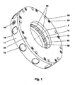
- FIGS. 1 to 4 show a brake and / or clamping device, as used for example for clamping of shafts used in tool and / or measuring machines.
- the device of the present embodiment is in this case on the corresponding machine part (5) arranged so that it surrounds the festzuklemmende shaft (1) usually with more than three Reibhememmen (60).
- On the shaft (1) are in the clamping of the Reibhememmen (60) moving friction elements (90-93).
- Each individual friction element (90-93) has a friction zone (95).
- the centroids (96) of the friction zones (95) lie, for example, in a plane which is oriented normal to the center line (2) of the shaft (1).
- the housing (10) consists essentially of a base body (11) and a lid (50). It has a diameter of 185 mm and a height of 35 mm in the embodiment.
- the base body (11) is an annular member having a central bore (15) surrounding the shaft (1) whose diameter is 90 mm here.
- stepped holes (25) are incorporated from the outside.
- the stepped holes (25) terminate in an annular groove (18) of the bore (15).
- the annular groove (18) has normal to the center line (2) aligned side walls.
- Their base is cylindrical.
- Each individual blind hole (27) parallel to the center line (2) is cut by a radial stepped bore (25).
- the main body (11) has a bottom (12) into which a flat, wide annular channel (23) is screwed.
- a narrow air duct (31) is incorporated in the bottom (24) of the annular channel (23), which is oriented parallel to the bottom (12). The latter cuts the blind holes (27).
- an annular disc (45) for gas-tight covering of the air duct (31) is glued, see. FIGS. 3 and 4 ,
- the upper side (13) of the main body (11) has, both offset inwards and outwards, on both sides of the blind holes (27) each a housing collar (33, 35).
- the inner housing collar (33) carries a thread (34), e.g. a fine thread M 100x1.
- a thread (34) e.g. a fine thread M 100x1.
- an annular channel for receiving a sealing ring (44). Both housing collars (33, 35) have e.g. the same height.
- threaded holes (36) for screwing the lid (50) are arranged in the region of the outer housing collar (35) in the region of the outer housing collar (35) 10 threaded holes (36) for screwing the lid (50) are arranged.
- the threaded holes (36) sit offset to the stepped holes (25).
- Next to each threaded hole (36) sits eg on the same hole circle a through hole (37) which ends in the bottom (12) of the base body (11) in a step reduction.
- the cover (50) On the upper side (13) of the main body (11) sits the lid (50), which rests at least on the outer housing collar (35).
- the cover (50) has an annular recess (51), the bottom surface (52) opposite to the openings of the blind holes (27).
- the bottom surface (52) of the recess (51) In the bottom surface (52) of the recess (51) is a narrow air duct (53) which connects the blind holes (27) with each other pneumatically.
- the inner cylindrical wall of the recess (51) is equipped with a fine thread.
- the cover In the area of the outer housing collar (35), the cover has a 45 ° bevel in order to pinch a sealing ring (43) in the groove of the housing collar (35) in a gastight manner.
- the upper air duct (53) In order to be able to supply or vent the upper air duct (53) with compressed air, it is provided via a bore (39), cf. FIG. 4 , connected to a double air connection (41).
- the lower air duct (31) is connected via a bore (32) with a double air connection (42) in connection.
- Both air connections (41, 42) terminate both in the underside (12) and in the radial outer wall (14) of the main body (11). At least one is closed by a plug (49).
- the cover (50) To mount the cover (50), it is first screwed onto the base body (11) via the fine thread (34) until the cover (50) rests on the inner housing collar (33). Then it will be the lid (50) turned back until the hole pattern of the lid (50) on the hole pattern of the threaded holes (36) fits. The swing angle of the back turn is less than 36 degrees. Finally, the lid (50) by means of screws (55) screwed to the base body (11).
- a friction element (90) In the annular groove (18) of the main body (11) per Reibhememme (60) a friction element (90), see. FIG. 5 and 2 arranged.
- the individual friction element (90) is a flat, elastic bending element (94), on each of which a fastening eye (97) is arranged on both sides.
- Each attachment eye (97) has a bore (98).
- the bending element (94) is compared with a plane formed by the two center lines of the holes (98), for example offset by 2.3 mm to the shaft (1).
- the bending element (94) here has an average wall thickness of 1.4 mm.
- the area that abuts the shaft (1) during clamping is the friction zone (95). It is in the exemplary embodiment FIG. 1 . 2 and 5 a part of a cylindrical surface.
- the bending element (94) is dimensionally stable in the region of the friction zone (95), while it is designed to be particularly flexible between the friction zone (95) and the fastening eyes (97).
- the friction zone (95) is coated, for example, with a friction lining made of a powder-metallurgically produced friction material based on bronze.
- the friction material may additionally contain ceramic constituents.
- the friction lining on the friction element (90-93) can also be glued or soldered.
- the width of the individual friction element (90) - measured parallel to the center line (2) - is chosen so that it fits with little play between the lateral flanks of the annular groove (18). It will be after FIG. 2 held in the annular groove (18) by means of spring pins (21).
- the spring pins (21) each pass through the holes (19) and (98). Instead of the spring pins (21) and grooved pins or cylindrical pins can be used. After assembly the unloaded friction elements (90) do not touch the shaft (1). Between the shaft (1) and the friction zone (95) is a release distance of 0.02 to 0.3 mm.
- the doubly supported friction element (90) sits at least in the circumferential direction without play in the base body (11).
- the shaft (1) is blocked during clamping relative to the housing (10) regardless of the direction of rotation of the torque to be held.
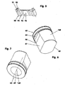
- FIG. 8 a one-sided or half-side in the base body (11) mounted friction element (91) is shown, the bending element (94) is angled in the attachment area by eg 90 degrees and ends in an integrally formed bolt (99).
- the bolt (99) is pressed into a housing-side bore.
- half of the friction elements (91) used per housing (10) have the same as in FIG. 8 illustrated shape, while the other half has a shape that is mirror-symmetrical to this.
- the plane of symmetry here is a plane formed by the intersecting center lines (2) and (26).
- FIG. 9 shows a Reibhememme in which the friction element (92) is a part of the base body (11, 59).
- the gap between the base body (11, 59) and the friction element (92) is machined out, for example, by wire erosion.
- the friction element (92) has here, for example, the shape of a flat plate.
- This figure also shows a Reibhememme, which is housed in a cuboid base body (59). From at least three e.g. Star-shaped around a shaft (1) rigidly placed Reibhememmen arises - after a pneumatic connection via compressed air lines - a brake and / or clamping device.
- FIGS. 10 and 11 show a further alternative, in which the base body (11) and the friction elements (93) of a part are made.
- a step (48) is turned off from the upper side (13) on the main body (11), in order then to pierce an annular channel (46) from the shoulder (48), which has a narrow web (16) opposite the bore wall (16). 17).
- the web width corresponds to the wall thickness of the friction element (93).
- a Reibhememme 60
- a Reibhememme 60
- the e.g. rotationally symmetrical pressure piece (73) It rests directly on the friction element (90) on the rear side of the friction zone (95).
- the pressure piece (73) is a cylindrical piston with an integrally formed piston rod.
- the piston rod projects completely into the annular groove (18), while the piston does this only in certain areas.
- On the piston there is a groove in which an elastic sealing ring (74) sits.
- Between the bottom of the stepped bore (25) and the piston is possibly a - not shown here - return stroke arranged.
- an adjusting screw (75) is adjustably mounted in the front region of the stepped bore (25).
- the adjusting screw (75) is a cylindrical disc having bores on the outer end face for engagement of a tenon wrench. It has an external thread that ends in an annular groove. In the annular groove a crimp ring (76) is embedded as a screw lock and a compressed air seal.
- the cage (81) which supports two cylindrical rollers (84, 85). Both cylindrical rollers (84, 85) abut on the sliding wedge (66) of a sliding wedge gear (61).
- the outer cylindrical roller (85) is supported on the adjusting screw (75), while the inner cylindrical roller (84) rests against the pressure piece (73).
- the latter has only a diameter of 21 mm, for example. He can also be chosen many millimeters smaller.
- a piston (63) surrounded by a cage (81) is arranged between the pressure piece (73) and the adjusting screw (75).
- a piston seal (65) separates the piston bottom side from the piston rod side (64).
- the completed, through the holes (25) and (27) formed; Located below the piston rod side (64) cavity forms the cylinder of a restoring, pneumatic cylinder-piston unit.
- the piston (63) has a central recess (69), e.g. in the form of a blind hole, in the embodiment, two spring elements (71, 72), e.g. two helical compression springs are arranged.
- spring elements e.g. two helical compression springs
- cup spring packs leaf springs, rubber springs, gas springs and the like can be used.
- the example one-piece spring guide element (56) consists of a support plate (57) and a molded pin (58). The pin (58) is with little play in the inner spring element (72).
- On the support plate (57) are the upper ends of the spring elements (71, 72).
- the piston (63) has instead of a piston rod, for example, a molded sliding wedge (66) in the form of a partially hollow cylinder, which is flattened on two opposite sides, see. FIGS. 6 and 7 .
- the sliding wedge (66) has inter alia a support (68) and a wedge surface (67). Both surfaces are square and, for example, flat.
- Each of the pressure piece (73) facing wedge surface (67) includes with this example, an acute angle of 1 to 5 degrees an.
- the support surface (68) extends parallel to the end face of the adjacent adjusting screw (75).
- the cross sections of the spline (66) taper linearly with increasing distance away from the piston rod side (64) of the piston (63).
- the cage (81) surrounding the sliding wedge (66), which is inserted transversely to the stepped bore (25) in the blind hole (27), is primarily in the form of a tube with two transverse slots (82) and several splayed abutment lips (83).
- the transverse slots (82) each serve to receive a cylindrical roller (84, 85).
- the abutment lips (83) are elastically outwardly resilient tongues that issue as soon as the cage (81) is inserted so deeply into the blind hole (27) that the abutment lips (83) spring free in the area of the stepped bore (27).
- a helical compression spring (88) are used to retrieve the cage (81).
- the return springs (88) push the cage (81) upwards. If the piston (63) rests against the cover (50), then the cage (81) is supported on the wall of the radial stepped bore (27) via the abutment lips (83), cf. FIG. 3 , right side of the figure.
- the lower air duct (31) lying in the main body (11) is supplied with compressed air, cf. FIGS. 3 and 4 .
- the piston (63) is pressed against the top of the cover (50) against the action of the spring elements (71, 72) and the cage (81) is in its upper position, cf. FIG. 3 , right side.
- the cylindrical rollers (84, 85) sit unloaded in the cage (81).
- the friction elements (90-93) do not contact the shaft (1).
- the latter can rotate freely or move longitudinally relative to the housing (10).
- the surfaces (67, 68) bear against the cylindrical rollers (84, 85) guided in the cage (81) as the sliding wedge stroke increases.
- the outer cylindrical roller (85) supports the sliding wedge (66) on the adjusting screw (75), while the inner cylindrical roller (84) pushes the pressure piece (73) against the resistance of the friction element (90) on the shaft (1).
- the cylindrical rollers (84, 85) now roll between the components (73, 66, 75) until, in the exemplary embodiment, an equilibrium of forces between the spring force of the housing (10) and the spring force of the spring elements (71, 72) has set. Then the Reibgehemme (60) - achieved in pure spring force effect - their maximum clamping force.
- the friction elements (90-93) rest against the shaft (1) via the friction zones (95).
- the braking torque is 200 ⁇ 50 Nm in the present embodiment.
- the piston bottom side (32) of the piston (63) can be acted upon with compressed air via the upper air duct (53).
- the braking torque increases to 400 ⁇ 100 Nm at an air pressure of 4 x 10 5 Pa.
- FIG. 12 shows a brake and / or clamping device, as used for example in many horizontal or vertical slide, inter alia, in tool and measuring machines.
- the device of the present embodiment is arranged on the corresponding device carriage such that it encompasses the guide rail (3) which predetermines the carriage longitudinal guide, each with two friction stops (60).
- the guide rail (3) is encompassed by a base body (11) on both sides.
- the in principle C-shaped main body (11) consists of a cuboid, which has transversely to its longitudinal extent a Umgriffsnut (22), for example, has a rectangular cross-section.
- a Umgriffsnut 22
- the guide rail (3) is placed in the space formed by the Umgriffsnut (22).
- the Umgriffsnutbreite is only slightly wider than the guide rail width in the area encompassed by the base body (11).
- Each housing half has a lid (50), which closes the blind holes (27) gas-tight.
- the individual splined gearing (61) is loaded, inter alia, by spring elements (71, 72) for holding the clamping forces of the respective friction retainer (60).
- spring elements 71, 72
- the sliding wedge (66) is formed as part of a combination of the piston (63) and a piston rod (160).
- the piston rod (160) is not guided here in a conventional gas-tight sealed bore, but sits - flattened on two sides - between two cylindrical rollers (84) and (85).
- One flattening is a sliding wedge flank (67), the other a supporting flank (68), cf. this too Figures 3 . 6 and 7 ,
- the combination of piston (63) and piston rod (160) has a e.g. cylindrical recess (69).
- the recess has a flat bore bottom (169) oriented normal to the piston's centerline (168).
- the bottom (166) of the piston rod (160) has, for example, a wall thickness of 2 mm.
- the spring elements (71, 72), here again two helical compression springs, are nested in the recess (69) and thus positioned in parallel with respect to the spring rate. They sit - with little space required - on the bottom of the hole (169) of the recess (69) and at the same time are based on the bottom surface (52) of the respective lid (50). Possibly. the internal helical compression spring (72) is guided on a central guide pin (167). The latter also shortens the response time of the device by its reduction in volume of the recess (69), if additionally the piston bottom side (62) of the piston (63) is loaded with compressed air for clamping.
- the guide pin (167) can also be arranged or molded on the cover (50).
- the recess (69) In order to use springs of different lengths when using nested helical compression springs, can the recess (69) also be designed as a stepped bore, so that, for example, the external helical compression spring (71) has a shorter spring length.
- the disc springs are, for example, in a mixed circuit - that is partly in the same direction and partly stacked alternately - arranged.
Landscapes
- Engineering & Computer Science (AREA)
- General Engineering & Computer Science (AREA)
- Mechanical Engineering (AREA)
- Braking Arrangements (AREA)
Applications Claiming Priority (1)
| Application Number | Priority Date | Filing Date | Title |
|---|---|---|---|
| DE102008020519A DE102008020519A1 (de) | 2008-04-23 | 2008-04-23 | Brems- und/oder Klemmvorrichtung für Wellen und Führungsschienen |
Publications (2)
| Publication Number | Publication Date |
|---|---|
| EP2112396A1 true EP2112396A1 (fr) | 2009-10-28 |
| EP2112396B1 EP2112396B1 (fr) | 2012-05-02 |
Family
ID=40756804
Family Applications (1)
| Application Number | Title | Priority Date | Filing Date |
|---|---|---|---|
| EP09005674A Not-in-force EP2112396B1 (fr) | 2008-04-23 | 2009-04-22 | Dispositif de freinage et/ou de serrage pour arbres et rails de guidage |
Country Status (3)
| Country | Link |
|---|---|
| EP (1) | EP2112396B1 (fr) |
| AT (1) | ATE556246T1 (fr) |
| DE (1) | DE102008020519A1 (fr) |
Cited By (4)
| Publication number | Priority date | Publication date | Assignee | Title |
|---|---|---|---|---|
| EP2410197A1 (fr) * | 2010-07-20 | 2012-01-25 | Hansen Industrial Transmissions | Système de freinage pour boîte de vitesse industrielle |
| CN103958917A (zh) * | 2011-11-11 | 2014-07-30 | Chr.迈尔有限公司及两合公司 | 压力介质操纵的制动器 |
| CN104033494A (zh) * | 2014-06-06 | 2014-09-10 | 嘉善天慧光电科技有限公司 | 滑动台锁紧装置 |
| CN105090297A (zh) * | 2015-08-28 | 2015-11-25 | 枣庄泰德机械有限公司 | 四齿轮联动式制动间隙调整装置 |
Families Citing this family (2)
| Publication number | Priority date | Publication date | Assignee | Title |
|---|---|---|---|---|
| DE102010045109B4 (de) * | 2010-09-13 | 2012-05-24 | Günther Zimmer | Vorrichtung mit hintereinander geschalteten Schiebekeilgetrieben |
| DE102019005877B3 (de) * | 2019-08-22 | 2020-12-31 | Günther Zimmer | Brems- und/oder Klemmelement mit innenliegendem Druckraum |
Citations (6)
| Publication number | Priority date | Publication date | Assignee | Title |
|---|---|---|---|---|
| US3995534A (en) * | 1973-06-30 | 1976-12-07 | Adolf Rastetter | Safety arrester for arresting a hydraulically operated lifting ram of a hydraulic elevator |
| DE20002915U1 (de) * | 2000-02-18 | 2000-08-10 | Zimmer Guenther Stephan | Brems- und/oder Klemmvorrichtung für Führungen |
| DE20202803U1 (de) * | 2002-02-22 | 2003-07-03 | Zimmer Gmbh Tech Werkstaetten | Reibgehemme mit Drillingskolbenentlastung |
| DE10207605C1 (de) | 2002-02-22 | 2003-08-21 | Zimmer Gmbh Tech Werkstaetten | Reibgehemme mit Drillingskolbenentlastung |
| US20050183907A1 (en) * | 2004-02-20 | 2005-08-25 | Maher Jeffrey M. | Motion control apparatus |
| WO2006108387A1 (fr) | 2005-04-11 | 2006-10-19 | Zimmer Guenther | Dispositif de freinage et/ou de blocage comportant une transmission à clavette logée sur paliers à roulement |
Family Cites Families (3)
| Publication number | Priority date | Publication date | Assignee | Title |
|---|---|---|---|---|
| US5540135A (en) * | 1994-12-27 | 1996-07-30 | Advanced Machine & Engineering Co. | Device for clamping an axially movable rod |
| DE19544534C2 (de) * | 1995-11-29 | 2000-05-04 | Rexroth Star Gmbh | Bremseinrichtung für eine Linearführungseinrichtung |
| DE29613345U1 (de) * | 1996-08-03 | 1996-10-10 | G & M Zimmer Ohg | Brems- und/oder Klemmvorrichtung für Führungen |
-
2008
- 2008-04-23 DE DE102008020519A patent/DE102008020519A1/de not_active Withdrawn
-
2009
- 2009-04-22 EP EP09005674A patent/EP2112396B1/fr not_active Not-in-force
- 2009-04-22 AT AT09005674T patent/ATE556246T1/de active
Patent Citations (6)
| Publication number | Priority date | Publication date | Assignee | Title |
|---|---|---|---|---|
| US3995534A (en) * | 1973-06-30 | 1976-12-07 | Adolf Rastetter | Safety arrester for arresting a hydraulically operated lifting ram of a hydraulic elevator |
| DE20002915U1 (de) * | 2000-02-18 | 2000-08-10 | Zimmer Guenther Stephan | Brems- und/oder Klemmvorrichtung für Führungen |
| DE20202803U1 (de) * | 2002-02-22 | 2003-07-03 | Zimmer Gmbh Tech Werkstaetten | Reibgehemme mit Drillingskolbenentlastung |
| DE10207605C1 (de) | 2002-02-22 | 2003-08-21 | Zimmer Gmbh Tech Werkstaetten | Reibgehemme mit Drillingskolbenentlastung |
| US20050183907A1 (en) * | 2004-02-20 | 2005-08-25 | Maher Jeffrey M. | Motion control apparatus |
| WO2006108387A1 (fr) | 2005-04-11 | 2006-10-19 | Zimmer Guenther | Dispositif de freinage et/ou de blocage comportant une transmission à clavette logée sur paliers à roulement |
Cited By (6)
| Publication number | Priority date | Publication date | Assignee | Title |
|---|---|---|---|---|
| EP2410197A1 (fr) * | 2010-07-20 | 2012-01-25 | Hansen Industrial Transmissions | Système de freinage pour boîte de vitesse industrielle |
| WO2012010586A1 (fr) * | 2010-07-20 | 2012-01-26 | Hansen Industrial Transmissions | Système de frein pour boîte de vitesse industrielle |
| CN103958917A (zh) * | 2011-11-11 | 2014-07-30 | Chr.迈尔有限公司及两合公司 | 压力介质操纵的制动器 |
| CN104033494A (zh) * | 2014-06-06 | 2014-09-10 | 嘉善天慧光电科技有限公司 | 滑动台锁紧装置 |
| CN105090297A (zh) * | 2015-08-28 | 2015-11-25 | 枣庄泰德机械有限公司 | 四齿轮联动式制动间隙调整装置 |
| CN105090297B (zh) * | 2015-08-28 | 2017-09-01 | 枣庄泰德机械有限公司 | 四齿轮联动式制动间隙调整装置 |
Also Published As
| Publication number | Publication date |
|---|---|
| EP2112396B1 (fr) | 2012-05-02 |
| DE102008020519A1 (de) | 2009-11-05 |
| ATE556246T1 (de) | 2012-05-15 |
Similar Documents
| Publication | Publication Date | Title |
|---|---|---|
| EP2396141B1 (fr) | Dispositif d'arrêt à friction avec cage transversale | |
| DE10252915B3 (de) | Reibgehemme mit Notbremsfunktion | |
| EP2112396B1 (fr) | Dispositif de freinage et/ou de serrage pour arbres et rails de guidage | |
| EP2299141B1 (fr) | Dispositif de freinage et/ou de serrage doté d'un corps central à forme rigide | |
| EP2395256B1 (fr) | Dispositif doté d'une soupape de mise en circuit | |
| EP3496899B1 (fr) | Dispositif de freinage et/ou de serrage comprenant un module d'actionnement et un module d'accouplement d'arbre | |
| DE10207605C1 (de) | Reibgehemme mit Drillingskolbenentlastung | |
| EP1468758B1 (fr) | Matrice pour jeu d'outils pour réaliser des joints mécaniques | |
| EP2813722A2 (fr) | Dispositif de serrage et/ou de freinage de chariot sur rail, doté d'une cage intégrée dans la tige de piston | |
| EP3403758B1 (fr) | Adaptateur réglable | |
| EP2112395B1 (fr) | Dispositif de freinage et/ou de serrage pour arbres | |
| EP2813723B1 (fr) | Dispositif de freinage et/ou de blocage de chariot sur rail, à zone de roulement oblique | |
| EP3512657B1 (fr) | Système d'outil | |
| EP2673523B1 (fr) | Appareil comportant une mécanique d'encliquetage | |
| DE102011121890A1 (de) | Brems- und/oder Klemmvorrichtung mit Betriebszustandsüberwachung | |
| DE102006062295A1 (de) | Klemmvorrichtung mit mindestens einem umgreifenden Klemmelement | |
| DE102005016723A1 (de) | Brems- und/oder Klemmvorrichtung mit wälzgelagertem Keilgetriebe | |
| DE10213127C1 (de) | Parallelgreifvorrichtung mit paarweise beweglichen Schlitten | |
| EP0325728B1 (fr) | Mandrin pour tige filetée | |
| EP1113954B1 (fr) | Systeme pour permettre l'appui d'une caisse sur un chassis | |
| DE19920264A1 (de) | Werkzeugaufnahme für eine Schnellfrequenzspindel | |
| DE20202803U1 (de) | Reibgehemme mit Drillingskolbenentlastung | |
| DE10060703A1 (de) | Drehmomentadapter | |
| DE20204667U1 (de) | Parallelgreifvorrichtung mit paarweise beweglichen Schlitten | |
| DE102005029708B4 (de) | Brems- und/oder Klemmvorrichtung mit mindestens einem umgreifenden Bremselement |
Legal Events
| Date | Code | Title | Description |
|---|---|---|---|
| PUAI | Public reference made under article 153(3) epc to a published international application that has entered the european phase |
Free format text: ORIGINAL CODE: 0009012 |
|
| AK | Designated contracting states |
Kind code of ref document: A1 Designated state(s): AT BE BG CH CY CZ DE DK EE ES FI FR GB GR HR HU IE IS IT LI LT LU LV MC MK MT NL NO PL PT RO SE SI SK TR |
|
| 17P | Request for examination filed |
Effective date: 20100420 |
|
| 17Q | First examination report despatched |
Effective date: 20100525 |
|
| GRAP | Despatch of communication of intention to grant a patent |
Free format text: ORIGINAL CODE: EPIDOSNIGR1 |
|
| GRAS | Grant fee paid |
Free format text: ORIGINAL CODE: EPIDOSNIGR3 |
|
| GRAA | (expected) grant |
Free format text: ORIGINAL CODE: 0009210 |
|
| AK | Designated contracting states |
Kind code of ref document: B1 Designated state(s): AT BE BG CH CY CZ DE DK EE ES FI FR GB GR HR HU IE IS IT LI LT LU LV MC MK MT NL NO PL PT RO SE SI SK TR |
|
| REG | Reference to a national code |
Ref country code: GB Ref legal event code: FG4D Free format text: NOT ENGLISH |
|
| REG | Reference to a national code |
Ref country code: AT Ref legal event code: REF Ref document number: 556246 Country of ref document: AT Kind code of ref document: T Effective date: 20120515 Ref country code: CH Ref legal event code: EP |
|
| REG | Reference to a national code |
Ref country code: IE Ref legal event code: FG4D Free format text: LANGUAGE OF EP DOCUMENT: GERMAN |
|
| REG | Reference to a national code |
Ref country code: DE Ref legal event code: R096 Ref document number: 502009003422 Country of ref document: DE Effective date: 20120628 |
|
| REG | Reference to a national code |
Ref country code: NL Ref legal event code: VDEP Effective date: 20120502 |
|
| REG | Reference to a national code |
Ref country code: LT Ref legal event code: MG4D Effective date: 20120502 |
|
| PG25 | Lapsed in a contracting state [announced via postgrant information from national office to epo] |
Ref country code: LT Free format text: LAPSE BECAUSE OF FAILURE TO SUBMIT A TRANSLATION OF THE DESCRIPTION OR TO PAY THE FEE WITHIN THE PRESCRIBED TIME-LIMIT Effective date: 20120502 Ref country code: SE Free format text: LAPSE BECAUSE OF FAILURE TO SUBMIT A TRANSLATION OF THE DESCRIPTION OR TO PAY THE FEE WITHIN THE PRESCRIBED TIME-LIMIT Effective date: 20120502 Ref country code: NO Free format text: LAPSE BECAUSE OF FAILURE TO SUBMIT A TRANSLATION OF THE DESCRIPTION OR TO PAY THE FEE WITHIN THE PRESCRIBED TIME-LIMIT Effective date: 20120802 Ref country code: FI Free format text: LAPSE BECAUSE OF FAILURE TO SUBMIT A TRANSLATION OF THE DESCRIPTION OR TO PAY THE FEE WITHIN THE PRESCRIBED TIME-LIMIT Effective date: 20120502 Ref country code: IS Free format text: LAPSE BECAUSE OF FAILURE TO SUBMIT A TRANSLATION OF THE DESCRIPTION OR TO PAY THE FEE WITHIN THE PRESCRIBED TIME-LIMIT Effective date: 20120902 Ref country code: CY Free format text: LAPSE BECAUSE OF FAILURE TO SUBMIT A TRANSLATION OF THE DESCRIPTION OR TO PAY THE FEE WITHIN THE PRESCRIBED TIME-LIMIT Effective date: 20120502 Ref country code: PL Free format text: LAPSE BECAUSE OF FAILURE TO SUBMIT A TRANSLATION OF THE DESCRIPTION OR TO PAY THE FEE WITHIN THE PRESCRIBED TIME-LIMIT Effective date: 20120502 |
|
| PG25 | Lapsed in a contracting state [announced via postgrant information from national office to epo] |
Ref country code: PT Free format text: LAPSE BECAUSE OF FAILURE TO SUBMIT A TRANSLATION OF THE DESCRIPTION OR TO PAY THE FEE WITHIN THE PRESCRIBED TIME-LIMIT Effective date: 20120903 Ref country code: GR Free format text: LAPSE BECAUSE OF FAILURE TO SUBMIT A TRANSLATION OF THE DESCRIPTION OR TO PAY THE FEE WITHIN THE PRESCRIBED TIME-LIMIT Effective date: 20120803 Ref country code: HR Free format text: LAPSE BECAUSE OF FAILURE TO SUBMIT A TRANSLATION OF THE DESCRIPTION OR TO PAY THE FEE WITHIN THE PRESCRIBED TIME-LIMIT Effective date: 20120502 Ref country code: SI Free format text: LAPSE BECAUSE OF FAILURE TO SUBMIT A TRANSLATION OF THE DESCRIPTION OR TO PAY THE FEE WITHIN THE PRESCRIBED TIME-LIMIT Effective date: 20120502 Ref country code: LV Free format text: LAPSE BECAUSE OF FAILURE TO SUBMIT A TRANSLATION OF THE DESCRIPTION OR TO PAY THE FEE WITHIN THE PRESCRIBED TIME-LIMIT Effective date: 20120502 |
|
| PG25 | Lapsed in a contracting state [announced via postgrant information from national office to epo] |
Ref country code: CZ Free format text: LAPSE BECAUSE OF FAILURE TO SUBMIT A TRANSLATION OF THE DESCRIPTION OR TO PAY THE FEE WITHIN THE PRESCRIBED TIME-LIMIT Effective date: 20120502 Ref country code: SK Free format text: LAPSE BECAUSE OF FAILURE TO SUBMIT A TRANSLATION OF THE DESCRIPTION OR TO PAY THE FEE WITHIN THE PRESCRIBED TIME-LIMIT Effective date: 20120502 Ref country code: EE Free format text: LAPSE BECAUSE OF FAILURE TO SUBMIT A TRANSLATION OF THE DESCRIPTION OR TO PAY THE FEE WITHIN THE PRESCRIBED TIME-LIMIT Effective date: 20120502 Ref country code: RO Free format text: LAPSE BECAUSE OF FAILURE TO SUBMIT A TRANSLATION OF THE DESCRIPTION OR TO PAY THE FEE WITHIN THE PRESCRIBED TIME-LIMIT Effective date: 20120502 Ref country code: NL Free format text: LAPSE BECAUSE OF FAILURE TO SUBMIT A TRANSLATION OF THE DESCRIPTION OR TO PAY THE FEE WITHIN THE PRESCRIBED TIME-LIMIT Effective date: 20120502 Ref country code: DK Free format text: LAPSE BECAUSE OF FAILURE TO SUBMIT A TRANSLATION OF THE DESCRIPTION OR TO PAY THE FEE WITHIN THE PRESCRIBED TIME-LIMIT Effective date: 20120502 |
|
| PLBE | No opposition filed within time limit |
Free format text: ORIGINAL CODE: 0009261 |
|
| STAA | Information on the status of an ep patent application or granted ep patent |
Free format text: STATUS: NO OPPOSITION FILED WITHIN TIME LIMIT |
|
| 26N | No opposition filed |
Effective date: 20130205 |
|
| PG25 | Lapsed in a contracting state [announced via postgrant information from national office to epo] |
Ref country code: ES Free format text: LAPSE BECAUSE OF FAILURE TO SUBMIT A TRANSLATION OF THE DESCRIPTION OR TO PAY THE FEE WITHIN THE PRESCRIBED TIME-LIMIT Effective date: 20120813 |
|
| REG | Reference to a national code |
Ref country code: DE Ref legal event code: R097 Ref document number: 502009003422 Country of ref document: DE Effective date: 20130205 |
|
| PG25 | Lapsed in a contracting state [announced via postgrant information from national office to epo] |
Ref country code: BG Free format text: LAPSE BECAUSE OF FAILURE TO SUBMIT A TRANSLATION OF THE DESCRIPTION OR TO PAY THE FEE WITHIN THE PRESCRIBED TIME-LIMIT Effective date: 20120802 |
|
| BERE | Be: lapsed |
Owner name: ZIMMER, MARTIN Effective date: 20130430 Owner name: ZIMMER, GUNTHER Effective date: 20130430 |
|
| PG25 | Lapsed in a contracting state [announced via postgrant information from national office to epo] |
Ref country code: MC Free format text: LAPSE BECAUSE OF FAILURE TO SUBMIT A TRANSLATION OF THE DESCRIPTION OR TO PAY THE FEE WITHIN THE PRESCRIBED TIME-LIMIT Effective date: 20120502 |
|
| REG | Reference to a national code |
Ref country code: CH Ref legal event code: PL |
|
| REG | Reference to a national code |
Ref country code: IE Ref legal event code: MM4A |
|
| PG25 | Lapsed in a contracting state [announced via postgrant information from national office to epo] |
Ref country code: CH Free format text: LAPSE BECAUSE OF NON-PAYMENT OF DUE FEES Effective date: 20130430 Ref country code: BE Free format text: LAPSE BECAUSE OF NON-PAYMENT OF DUE FEES Effective date: 20130430 Ref country code: LI Free format text: LAPSE BECAUSE OF NON-PAYMENT OF DUE FEES Effective date: 20130430 |
|
| PG25 | Lapsed in a contracting state [announced via postgrant information from national office to epo] |
Ref country code: IE Free format text: LAPSE BECAUSE OF NON-PAYMENT OF DUE FEES Effective date: 20130422 |
|
| PG25 | Lapsed in a contracting state [announced via postgrant information from national office to epo] |
Ref country code: MT Free format text: LAPSE BECAUSE OF FAILURE TO SUBMIT A TRANSLATION OF THE DESCRIPTION OR TO PAY THE FEE WITHIN THE PRESCRIBED TIME-LIMIT Effective date: 20120502 |
|
| REG | Reference to a national code |
Ref country code: AT Ref legal event code: MM01 Ref document number: 556246 Country of ref document: AT Kind code of ref document: T Effective date: 20140422 |
|
| PG25 | Lapsed in a contracting state [announced via postgrant information from national office to epo] |
Ref country code: TR Free format text: LAPSE BECAUSE OF FAILURE TO SUBMIT A TRANSLATION OF THE DESCRIPTION OR TO PAY THE FEE WITHIN THE PRESCRIBED TIME-LIMIT Effective date: 20120502 |
|
| PG25 | Lapsed in a contracting state [announced via postgrant information from national office to epo] |
Ref country code: LU Free format text: LAPSE BECAUSE OF NON-PAYMENT OF DUE FEES Effective date: 20130422 Ref country code: HU Free format text: LAPSE BECAUSE OF FAILURE TO SUBMIT A TRANSLATION OF THE DESCRIPTION OR TO PAY THE FEE WITHIN THE PRESCRIBED TIME-LIMIT; INVALID AB INITIO Effective date: 20090422 Ref country code: MK Free format text: LAPSE BECAUSE OF FAILURE TO SUBMIT A TRANSLATION OF THE DESCRIPTION OR TO PAY THE FEE WITHIN THE PRESCRIBED TIME-LIMIT Effective date: 20120502 |
|
| PG25 | Lapsed in a contracting state [announced via postgrant information from national office to epo] |
Ref country code: AT Free format text: LAPSE BECAUSE OF NON-PAYMENT OF DUE FEES Effective date: 20140422 |
|
| REG | Reference to a national code |
Ref country code: FR Ref legal event code: PLFP Year of fee payment: 8 |
|
| REG | Reference to a national code |
Ref country code: FR Ref legal event code: PLFP Year of fee payment: 9 |
|
| REG | Reference to a national code |
Ref country code: FR Ref legal event code: PLFP Year of fee payment: 10 |
|
| PGFP | Annual fee paid to national office [announced via postgrant information from national office to epo] |
Ref country code: GB Payment date: 20240423 Year of fee payment: 16 |
|
| PGFP | Annual fee paid to national office [announced via postgrant information from national office to epo] |
Ref country code: DE Payment date: 20240418 Year of fee payment: 16 |
|
| PGFP | Annual fee paid to national office [announced via postgrant information from national office to epo] |
Ref country code: IT Payment date: 20240426 Year of fee payment: 16 Ref country code: FR Payment date: 20240423 Year of fee payment: 16 |
|
| REG | Reference to a national code |
Ref country code: DE Ref legal event code: R119 Ref document number: 502009003422 Country of ref document: DE |
|
| GBPC | Gb: european patent ceased through non-payment of renewal fee |
Effective date: 20250422 |
|
| PG25 | Lapsed in a contracting state [announced via postgrant information from national office to epo] |
Ref country code: DE Free format text: LAPSE BECAUSE OF NON-PAYMENT OF DUE FEES Effective date: 20251104 |
|
| PG25 | Lapsed in a contracting state [announced via postgrant information from national office to epo] |
Ref country code: GB Free format text: LAPSE BECAUSE OF NON-PAYMENT OF DUE FEES Effective date: 20250422 |
|
| PG25 | Lapsed in a contracting state [announced via postgrant information from national office to epo] |
Ref country code: FR Free format text: LAPSE BECAUSE OF NON-PAYMENT OF DUE FEES Effective date: 20250430 |
|
| PG25 | Lapsed in a contracting state [announced via postgrant information from national office to epo] |
Ref country code: IT Free format text: LAPSE BECAUSE OF NON-PAYMENT OF DUE FEES Effective date: 20250422 |