EP2410197A1 - Système de freinage pour boîte de vitesse industrielle - Google Patents
Système de freinage pour boîte de vitesse industrielle Download PDFInfo
- Publication number
- EP2410197A1 EP2410197A1 EP10170120A EP10170120A EP2410197A1 EP 2410197 A1 EP2410197 A1 EP 2410197A1 EP 10170120 A EP10170120 A EP 10170120A EP 10170120 A EP10170120 A EP 10170120A EP 2410197 A1 EP2410197 A1 EP 2410197A1
- Authority
- EP
- European Patent Office
- Prior art keywords
- brake
- cylinders
- hydraulic
- gearbox
- brake system
- Prior art date
- Legal status (The legal status is an assumption and is not a legal conclusion. Google has not performed a legal analysis and makes no representation as to the accuracy of the status listed.)
- Granted
Links
- 230000008878 coupling Effects 0.000 claims description 30
- 238000010168 coupling process Methods 0.000 claims description 30
- 238000005859 coupling reaction Methods 0.000 claims description 30
- 230000000694 effects Effects 0.000 description 25
- 238000012423 maintenance Methods 0.000 description 24
- 238000001816 cooling Methods 0.000 description 3
- 238000004519 manufacturing process Methods 0.000 description 2
- 230000033228 biological regulation Effects 0.000 description 1
- 230000007423 decrease Effects 0.000 description 1
- 238000009434 installation Methods 0.000 description 1
- 238000003801 milling Methods 0.000 description 1
Images


Classifications
-
- F—MECHANICAL ENGINEERING; LIGHTING; HEATING; WEAPONS; BLASTING
- F16—ENGINEERING ELEMENTS AND UNITS; GENERAL MEASURES FOR PRODUCING AND MAINTAINING EFFECTIVE FUNCTIONING OF MACHINES OR INSTALLATIONS; THERMAL INSULATION IN GENERAL
- F16D—COUPLINGS FOR TRANSMITTING ROTATION; CLUTCHES; BRAKES
- F16D63/00—Brakes not otherwise provided for; Brakes combining more than one of the types of groups F16D49/00 - F16D61/00
-
- B—PERFORMING OPERATIONS; TRANSPORTING
- B60—VEHICLES IN GENERAL
- B60T—VEHICLE BRAKE CONTROL SYSTEMS OR PARTS THEREOF; BRAKE CONTROL SYSTEMS OR PARTS THEREOF, IN GENERAL; ARRANGEMENT OF BRAKING ELEMENTS ON VEHICLES IN GENERAL; PORTABLE DEVICES FOR PREVENTING UNWANTED MOVEMENT OF VEHICLES; VEHICLE MODIFICATIONS TO FACILITATE COOLING OF BRAKES
- B60T1/00—Arrangements of braking elements, i.e. of those parts where braking effect occurs specially for vehicles
- B60T1/005—Arrangements of braking elements, i.e. of those parts where braking effect occurs specially for vehicles by locking of wheel or transmission rotation
-
- F—MECHANICAL ENGINEERING; LIGHTING; HEATING; WEAPONS; BLASTING
- F16—ENGINEERING ELEMENTS AND UNITS; GENERAL MEASURES FOR PRODUCING AND MAINTAINING EFFECTIVE FUNCTIONING OF MACHINES OR INSTALLATIONS; THERMAL INSULATION IN GENERAL
- F16D—COUPLINGS FOR TRANSMITTING ROTATION; CLUTCHES; BRAKES
- F16D49/00—Brakes with a braking member co-operating with the periphery of a drum, wheel-rim, or the like
-
- F—MECHANICAL ENGINEERING; LIGHTING; HEATING; WEAPONS; BLASTING
- F16—ENGINEERING ELEMENTS AND UNITS; GENERAL MEASURES FOR PRODUCING AND MAINTAINING EFFECTIVE FUNCTIONING OF MACHINES OR INSTALLATIONS; THERMAL INSULATION IN GENERAL
- F16D—COUPLINGS FOR TRANSMITTING ROTATION; CLUTCHES; BRAKES
- F16D2121/00—Type of actuator operation force
- F16D2121/02—Fluid pressure
- F16D2121/04—Fluid pressure acting on a piston-type actuator, e.g. for liquid pressure
Definitions
- the present invention relates to an industrial gearbox. More particularly, the present invention relates to a brake system for an industrial gearbox and to an industrial gearbox and brake system assembly comprising such a brake system.
- Gear systems for gearboxes are widely known, especially in automotive.
- requirements for brake systems for gearboxes in automotive are quite different from requirements for gearboxes for industrial applications, such as, for example, cooling towers.
- Gear systems for use in gearboxes for such industrial applications are required for slowing them down and stop them from turning and to, after being stopped, hold the gear unit. This may, for example, be required for being able to safely perform maintenance activities.
- a big disadvantage is that the interface for attaching these brake systems to the gearbox differs depending on the size and kind of gearbox and on the specifications per supplier.
- a specific example of a known brake system may be a brake system of a cooling tower.
- the gear units of such cooling towers are mostly equipped with a backstop so that in one direction there is no rotation of the big fan possible.
- the fan can rotate slowly in the other direction. Therefore, the fan has to be stopped and blocked to insure a safe working because otherwise, people are in danger.
- a brake system according to embodiments of the invention may be at least partly movable, which means that such brake systems are not, or only partly, have to be provided on the gearbox during manufacturing, which significantly decreases the total cost of the gearbox.
- a brake system according to embodiments of the invention may be at least partly provided to customers separately from the gearbox and such brake system can be used for more than one gearbox.
- the present invention provides a brake system for an industrial gearbox.
- the brake system comprises two hydraulic brake cylinders, each hydraulic brake cylinder comprising a brake shoe.
- the brake system furthermore comprises a device for causing movement of the hydraulic brake cylinders and brake lines for connecting each of the hydraulic brake cylinders to the device for causing movement of the hydraulic brake cylinders.
- An advantage of a brake system according to embodiments of the invention and a gearbox comprising such a brake system is that, when maintenance or component replacement activities are required, the brake system can easily be connected to a lantern of the gearbox and can, when such maintenance or component replacement activities are finished, easily be removed from the lantern.
- the brake system may be a mobile brake system, which means that the hydraulic brake cylinders may be adapted for removably and repeatedly being connected to a lantern of the industrial gearbox and the brake lines and the device for causing movement of the hydraulic brake cylinders may be adapted for being removably connected to the hydraulic brake cylinders.
- An advantage hereof is that a brake system according to embodiments of the invention can be used for more than one gearbox, which significantly reduces the total cost of the gearboxes.
- the hydraulic brake cylinders may be connected to the lantern of the gearbox and the brake lines with attached or connected thereto the device for causing movement of the hydraulic brake cylinders may be connected to the hydraulic brake cylinders. After such maintenance or component replacement activities the complete brake system may be easily removed from the lantern of the gearbox.
- the brake system may be a stationary brake system, which means that the hydraulic brake cylinders may be adapted for being permanently connected to a lantern of the industrial gearbox and the brake lines and the device for causing movement of the hydraulic brake cylinders may be adapted for being removably connected to the hydraulic brake cylinders.
- the brake lines with attached or connected thereto the device for causing movement of the hydraulic brake cylinders may be connected to the hydraulic brake cylinders.
- the brake lines with attached or connected thereto the device for causing movement of the hydraulic brake cylinders may be easily removed from the hydraulic brake cylinders.
- the hydraulic brake cylinders are permanently mounted on the lantern of the gearbox and the brake lines and the device for causing movement of the hydraulic brake cylinders may be used for more than one gearbox.
- a brake system according to these embodiments still leads to cheaper gearboxes than prior art gearboxes with brake systems.
- the present invention provides a brake system for an industrial gearbox, the brake system comprising
- the brake system may furthermore comprise brake line coupling elements for connecting the brake lines to the hydraulic brake cylinders.
- the brake system may furthermore comprise a control switch at each of the hydraulic cylinders for controlling the position of the brake shoes.
- the device for causing movement of the hydraulic brake cylinders may be any device known by a person skilled in the art which is suitable for causing such movement.
- the device for causing movement of the hydraulic brake cylinders may be a pump.
- the present invention provides an industrial gearbox and brake system assembly, the industrial gearbox comprising a lantern for connecting the gearbox with a driving motor.
- the brake system comprises two hydraulic brake cylinders provided at opposite sides of the lantern, each hydraulic brake cylinder comprising a brake shoe.
- the brake system furthermore comprises a device for causing movement of the hydraulic brake cylinders and brake lines for connecting each of the hydraulic cylinders to the device for causing movement of the hydraulic brake cylinders.
- the brake system may be a mobile brake system, which means that the hydraulic brake cylinders may be removably connected to the lantern and the brake lines and the device for causing movement of the hydraulic brake cylinders may be removably connected to the hydraulic brake cylinders.
- An advantage hereof is that a brake system according to embodiments of the invention can be used for more than one gearbox, which significantly reduces the total cost of the gearboxes.
- the brake system may be a stationary brake system, which means that the hydraulic brake cylinders may be permanently connected to the lantern and the brake lines and the device for causing movement of the hydraulic brake cylinders may be removably connected to the hydraulic brake cylinders.
- the hydraulic brake cylinders are fixedly and permanently mounted on the lantern of the gearbox and the brake lines and the device for causing movement of the hydraulic brake cylinders may be used for more than one gearbox.
- a brake system according to these embodiments still leads to cheaper gearboxes than prior art gearboxes with brake systems.
- the invention provides an industrial gearbox and brake system assembly, the industrial gearbox comprising a lantern for connecting the gearbox to a driving motor, and the brake system comprising:
- the brake lines may be connected to the hydraulic brake cylinders by means of brake line coupling elements.
- the brake system may furthermore comprise a control switch at each of the hydraulic brake cylinders for controlling the position of the brake shoe.
- the device for causing movement of the hydraulic brake cylinders may be any device known by a person skilled in the art which is suitable for causing such movement.
- the device for causing movement of the hydraulic brake cylinders may be a pump.
- the lantern of a gearbox may comprise a coupling for transferring torque of a shaft of the driving motor to an input shaft of the gearbox and, according to embodiments of the invention, the brake system may be mounted on the lantern such that the brake shoes of the hydraulic brake cylinders are axially aligned with each other and with a flange of the coupling as considered in a direction along the longitudinal axis of the hydraulic brake cylinders.
- part A being connected to part B is not limited to part A being in direct contact to part B, but also includes indirect contact between part A and part B, in other words also includes the case where intermediate parts are present in between part A and part B.
- part A being connected to part B is not limited to part A being in direct contact to part B, but also includes indirect contact between part A and part B, in other words also includes the case where intermediate parts are present in between part A and part B.
- Not all embodiments of the invention comprise all features of the invention. In the following description and claims, any of the claimed embodiments can be used in any combination.
- the present invention provides a brake system for an industrial gearbox and an industrial gearbox and brake system assembly comprising such a brake system.
- the present invention provides a brake system for an industrial gearbox, the brake system comprising two hydraulic brake cylinders, each hydraulic brake cylinder comprising a brake shoe.
- the brake system furthermore comprises a device for causing movement of the hydraulic brake cylinders and brake lines for connecting each of the hydraulic brake cylinders to the device for causing movement of the hydraulic brake cylinders.
- Fig. 1 illustrates a cross section of a brake system 13 according to embodiments of the present invention mounted on an industrial gearbox.
- the industrial gearbox comprises an input shaft 10 which is to be connected to a driving motor (not shown) via a lantern 12.
- the brake system 13 is connected to the lantern 12.
- the brake system 13 comprises two hydraulic brake cylinders 15.
- Each of the hydraulic brake cylinders 15 comprises a brake shoe 16.
- the brake system 13 furthermore comprises brake lines 17, which may also be referred to as brake pipes, for connecting each of the two hydraulic brake cylinders 15 to a device 18 for causing movement of the hydraulic brake cylinders 15.
- Fig. 2 which illustrates a brake system 13 according to embodiments of the invention.
- the device 18 for causing movement of the hydraulic brake cylinders 15 may be any device known by a person skilled in the art which is suitable for causing movement of the hydraulic brake cylinders 15.
- the device 18 for causing movement of the hydraulic brake cylinders 15 may be a pump 18.
- the brake lines 17 may be connected to the hydraulic brake cylinders 15 by brake line coupling elements 19.
- the brake system 13 may be a mobile brake system, which means that the hydraulic brake cylinders 15 may be adapted for removably and repeatedly being connected to the lantern 12 of the industrial gearbox 20 and the brake lines 17 and the device 18 for causing movement of the hydraulic brake cylinders 15 may be adapted for being removably connected to the hydraulic brake cylinders 15.
- An advantage hereof is that a brake system 13 according to embodiments of the invention can be used for more than one gearbox 20, which significantly reduces the total cost of the industrial gearboxes 13.
- the hydraulic brake cylinders 15 may be connected to the lantern 12 of the industrial gearbox 20 and the brake lines 17 and the device 18 for causing movement of the hydraulic brake cylinders 15 may be connected to the hydraulic brake cylinders 15. After such maintenance or component replacement activities the complete brake system 13 may be easily removed from the lantern 12 of the industrial gearbox 20.
- the brake system 13 may be a stationary brake system, which means that the hydraulic brake cylinders 15 may be adapted for being permanently connected to a lantern 12 of the industrial gearbox 20 and the brake lines 17 and the device 18 for causing movement of the hydraulic brake cylinders 15 may be adapted for being removably connected to the hydraulic brake cylinders 15.
- the brake lines 17 with attached or connected thereto the device 18 for causing movement of the hydraulic brake cylinders 15 may be connected to the hydraulic brake cylinders 15.
- the brake lines 17 with attached or connected thereto the device 18 for causing movement of the hydraulic brake cylinders 15 may be easily removed from the hydraulic brake cylinders 15.
- the hydraulic brake cylinders 15 may be permanently mounted on the lantern of the industrial gearbox 20 and the brake lines 17 and the device 18 for causing movement of the hydraulic brake cylinders 15 may be used for more than one gearbox 20.
- a brake system 13 according to these embodiments still leads to cheaper industrial gearboxes 13 than prior art gearboxes with brake systems.
- the brake system 13 may furthermore comprise a control switch at each of the hydraulic cylinders 15 for controlling the position of the brake shoes 16. Controlling the position of the brake shoes 16 may, next to other safety measures, be important to prevent the industrial gearbox 20 from being switched on for as long as the hydraulic brake cylinders 15 are in a brake position.
- the present invention also provides an industrial gearbox and brake system assembly.
- the industrial gearbox comprises a lantern 12 for connecting the industrial gearbox 20 with a driving motor 11, and a brake system 13.
- the brake system 13 comprises two hydraulic brake cylinders 15 provided at opposite sides of the lantern 12, each hydraulic brake cylinder 15 comprising a brake shoe 16.
- the brake system 13 furthermore comprises a device 18 for causing movement of the hydraulic brake cylinders 15 and brake lines 17 for connecting each of the hydraulic cylinders 15 to the device 18 for causing movement of the hydraulic brake cylinders 15.
- the device 18 for causing movement of the hydraulic brake cylinders 15 may be any device known by a person skilled in the art which is suitable for causing movement of the hydraulic brake cylinders 15. According to specific embodiments of the invention, the device 18 for causing movement of the hydraulic brake cylinders 15 may be a pump 18.
- the brake system 13 is mounted on the lantern 12 of the industrial gearbox (not shown). Inside the lantern 12 a coupling 21 is present for transferring torque of a motor shaft to an input shaft 10 of the industrial gearbox 20.
- the coupling 21 as shown in Fig. 3 is only one half of a coupling, the other half is provided on the motor 11.
- coupling 21 is mentioned, this is intended to indicate that half of the coupling which is present in the lantern 12.
- the brake system 13 is mounted on the lantern 12 such that the brake shoes 16 of the hydraulic brake cylinders 15 are axially aligned with each other and with a flange 22 of the coupling 21 as considered in a direction along the longitudinal axis of the hydraulic brake cylinders 15.
- the brake line coupling elements 19 provided on the hydraulic brake cylinders 15 are located outside the lantern 12, such that the brake lines 17 can easily be connected to the hydraulic brake cylinders 15.
- the brake system 13 may furthermore comprise a control switch at each of the hydraulic cylinders 15 for controlling the position of the brake shoes 16.
- Controlling the position of the brake shoes 16 may, next to other safety measures, be important to prevent the industrial gearbox 20 from being switched on for as long as the hydraulic brake cylinders 15 are in a brake position, in other words for as long as the brake shoes 16 of the hydraulic brake cylinders 15 are in contact with flange 22 of the coupling 21 in the lantern 12.
- the brake system 13 may be a stationary brake system.
- stationary brake system is meant that the hydraulic brake cylinders 15 may be permanently connected to the lantern 12 and the pump 18 and brake lines 17 may then be connected to the hydraulic brake cylinders 15 when required, for example for maintenance or component replacement activities (see Fig. 4 ).
- the hydraulic brake cylinders 15 may be adapted for permanently being fixed to the lantern 12 of the gearbox 20.
- permanently connected is meant that the hydraulic brake cylinders 15 are intended to stay connected to the lantern 12 of the gearbox 20 at any time. Connecting the hydraulic brake cylinders 15 to the lantern 12 may, for example, be done by means of bolts.
- the two hydraulic brake cylinders 15 are mounted at opposite sides of the lantern 12 of the gearbox 20 and the gearbox 20 is delivered to customers as such.
- the brake lines 17 with the brake line coupling elements 19 and the pump 18 can then separately be delivered. This may be done in any suitable configuration.
- the brake lines 17 with attached or connected thereto the pump 18 at one side and the brake line coupling elements 19 at another side can separately be delivered or the brake lines with attached thereto the brake line coupling elements 19 can be delivered separately from the pump 18.
- the brake lines 17 with connected thereto the pump 18 and the brake line coupling elements 19 may be connected to the hydraulic brake cylinders 15 which are fixed on the lantern 12 of the gearbox 20.
- the brake line coupling elements 19 at one end of the brake lines 17 are in these cases adapted to be removably connected to the hydraulic brake cylinders 15 and can easily be removed and transferred to other gearboxes 20.
- removably connected is meant that the brake lines 17 and the pump 18 are attached or connected to the hydraulic brake cylinders 15 in such a way that they can easily be removed after performing maintenance or component replacement activities.
- An advantage of these embodiments is that cost can be partly reduced as the number of pumps 18 in combination with brake lines 17 and brake line coupling elements 19 can be lowered with respect to the case where a brake system 13 has to be provided on every gearbox 20, as is the case for prior art brake systems.
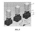
- the brake system 13 may be a mobile brake system (see Fig. 5 ).
- the complete brake system 13 may be intended for being connected to the lantern 12 of the gearbox 20 only when maintenance or component replacement activities have to be performed.
- the hydraulic brake cylinders 15 are adapted for removably and repeatedly being connected to the lantern 12 of the gearbox 20.
- removably connected is meant that the hydraulic brake cylinders 15 are attached or connected to the lantern 12 of the gearbox 20 in such a way that they can easily be removed after performing maintenance or component replacement activities.
- the brake lines 17 with attached or connected thereto the pump 18 may be connected to the hydraulic brake cylinders 15 in such a way that they can, at any time, easily be removed from the hydraulic brake cylinders 15.
- the complete brake system 13 may be delivered to customers separately from the gearbox 20.
- the gearbox 20 may in such cases, for example be delivered to the customer with a cover 23 on the interface.
- interface is meant the location on the lantern 12 where the brake system 13 has to be mounted.
- the customer can chose how many pumps 18 are required.
- no hydraulic brake cylinders 15 are to be provided on the gearbox 20, the total cost can even be more reduces with respect to the previous embodiment.
- the brake shoes 16 are permanently provided in the lantern 12 of the industrial gearbox 20.
- An advantage of a brake system 13 according to embodiments of the invention and a gearbox 20 comprising such a brake system 13 is that, when maintenance or component replacement activities are required, at least part of the brake system 13 can easily be connected to the lantern 12 of the gearbox 20 and can, when maintenance or component replacement activities are finished, easily and at least partly be removed from the lantern 12.
- the device 18 for causing movement of the hydraulic brake cylinders 15 provides forces to both the hydraulic brake cylinders 15 in a symmetrical way.
- the pump 18 provides oil to the hydraulic brake cylinders 15.
- the oil pressure increases proportional in both hydraulic brake cylinders 15.
- the hydraulic brake cylinders 15 and thus also the brake shoes 16 will move in a direction of the coupling 21.
- the brake shoes 16 will touch the coupling 21, and more particularly the flange 22 of the coupling 21 at opposite sides.
- the brake shoes 16 are self-aligning, thereby providing a uniform load to the flange 22 of the coupling 21.
- the oil pressure will further increase to a pre-determined value. From the moment the pre-determined value of oil pressure is achieved, the gearbox 20 will no longer be able to freely rotate and thus stops rotating.
- An advantage of the brake system 13 according to embodiments of the invention is that the pressure is uniformly provided at both sides of the flange 22 through which no radial load is exerted to shaft ends of the motor 11 and/or the gearbox 20. A too high radial load on shaft ends may have a negative influence on parts of the motor 11 and/or industrial gearbox 13, such as for example bearings.
- braking power is exerted only on one half of the coupling 21, i.e. the coupling 21 in the lantern 12, through which, during maintenance or component replacement activities, the motor 11 can be removed, in that way reducing risks for the persons performing maintenance activities.
- the hydraulic brake cylinders 15 can be mechanically blocked in their brake position and the pressure can then be relieved from the cylinders 15. Because of that, the brake system 13 works pressure-less during maintenance or component replacement activities and is thus insensitive for failure because of pressure loss.
Landscapes
- Engineering & Computer Science (AREA)
- General Engineering & Computer Science (AREA)
- Mechanical Engineering (AREA)
- Transportation (AREA)
- Braking Arrangements (AREA)
Priority Applications (5)
| Application Number | Priority Date | Filing Date | Title |
|---|---|---|---|
| EP20100170120 EP2410197B1 (fr) | 2010-07-20 | 2010-07-20 | Système de freinage pour boîte de vitesse industrielle |
| ES11733858T ES2530627T3 (es) | 2010-07-20 | 2011-07-19 | Sistema de freno para un reductor industrial |
| CN201180035229.3A CN103003590B (zh) | 2010-07-20 | 2011-07-19 | 一种工业齿轮箱及齿轮箱组件 |
| PCT/EP2011/062328 WO2012010586A1 (fr) | 2010-07-20 | 2011-07-19 | Système de frein pour boîte de vitesse industrielle |
| EP11733858.2A EP2596262B1 (fr) | 2010-07-20 | 2011-07-19 | Système de frein pour réducteur industriel |
Applications Claiming Priority (1)
| Application Number | Priority Date | Filing Date | Title |
|---|---|---|---|
| EP20100170120 EP2410197B1 (fr) | 2010-07-20 | 2010-07-20 | Système de freinage pour boîte de vitesse industrielle |
Publications (2)
| Publication Number | Publication Date |
|---|---|
| EP2410197A1 true EP2410197A1 (fr) | 2012-01-25 |
| EP2410197B1 EP2410197B1 (fr) | 2014-12-24 |
Family
ID=43127706
Family Applications (2)
| Application Number | Title | Priority Date | Filing Date |
|---|---|---|---|
| EP20100170120 Not-in-force EP2410197B1 (fr) | 2010-07-20 | 2010-07-20 | Système de freinage pour boîte de vitesse industrielle |
| EP11733858.2A Active EP2596262B1 (fr) | 2010-07-20 | 2011-07-19 | Système de frein pour réducteur industriel |
Family Applications After (1)
| Application Number | Title | Priority Date | Filing Date |
|---|---|---|---|
| EP11733858.2A Active EP2596262B1 (fr) | 2010-07-20 | 2011-07-19 | Système de frein pour réducteur industriel |
Country Status (4)
| Country | Link |
|---|---|
| EP (2) | EP2410197B1 (fr) |
| CN (1) | CN103003590B (fr) |
| ES (1) | ES2530627T3 (fr) |
| WO (1) | WO2012010586A1 (fr) |
Cited By (1)
| Publication number | Priority date | Publication date | Assignee | Title |
|---|---|---|---|---|
| EP2781783A1 (fr) | 2013-03-15 | 2014-09-24 | Siemens Aktiengesellschaft | Dispositif de freinage mobile |
Citations (3)
| Publication number | Priority date | Publication date | Assignee | Title |
|---|---|---|---|---|
| US6551027B2 (en) * | 2000-06-05 | 2003-04-22 | Stolt Offshore Limited | Pipe handling apparatus and method of using the same |
| EP1514758A1 (fr) * | 2003-09-12 | 2005-03-16 | Formula S.r.L. | Dispositif de raccordement d' un étrier de frein et une pompe pour des freins hydrauliques |
| EP2112396A1 (fr) * | 2008-04-23 | 2009-10-28 | Zimmer, Gunther | Dispositif de freinage et/ou de serrage pour arbres et rails de guidage |
Family Cites Families (3)
| Publication number | Priority date | Publication date | Assignee | Title |
|---|---|---|---|---|
| GB1409238A (en) * | 1971-09-09 | 1975-10-08 | Girling Ltd | Brakes for vehicles |
| JPS59169437U (ja) * | 1983-04-28 | 1984-11-13 | 柳井 茂 | ブレ−キ装置 |
| CN201496443U (zh) * | 2009-07-03 | 2010-06-02 | 西安宏信矿热炉有限公司 | 蝶簧式抱闸 |
-
2010
- 2010-07-20 EP EP20100170120 patent/EP2410197B1/fr not_active Not-in-force
-
2011
- 2011-07-19 EP EP11733858.2A patent/EP2596262B1/fr active Active
- 2011-07-19 ES ES11733858T patent/ES2530627T3/es active Active
- 2011-07-19 WO PCT/EP2011/062328 patent/WO2012010586A1/fr not_active Ceased
- 2011-07-19 CN CN201180035229.3A patent/CN103003590B/zh active Active
Patent Citations (3)
| Publication number | Priority date | Publication date | Assignee | Title |
|---|---|---|---|---|
| US6551027B2 (en) * | 2000-06-05 | 2003-04-22 | Stolt Offshore Limited | Pipe handling apparatus and method of using the same |
| EP1514758A1 (fr) * | 2003-09-12 | 2005-03-16 | Formula S.r.L. | Dispositif de raccordement d' un étrier de frein et une pompe pour des freins hydrauliques |
| EP2112396A1 (fr) * | 2008-04-23 | 2009-10-28 | Zimmer, Gunther | Dispositif de freinage et/ou de serrage pour arbres et rails de guidage |
Cited By (1)
| Publication number | Priority date | Publication date | Assignee | Title |
|---|---|---|---|---|
| EP2781783A1 (fr) | 2013-03-15 | 2014-09-24 | Siemens Aktiengesellschaft | Dispositif de freinage mobile |
Also Published As
| Publication number | Publication date |
|---|---|
| EP2596262B1 (fr) | 2014-12-03 |
| EP2410197B1 (fr) | 2014-12-24 |
| CN103003590B (zh) | 2015-10-21 |
| ES2530627T3 (es) | 2015-03-04 |
| CN103003590A (zh) | 2013-03-27 |
| WO2012010586A1 (fr) | 2012-01-26 |
| EP2596262A1 (fr) | 2013-05-29 |
Similar Documents
| Publication | Publication Date | Title |
|---|---|---|
| US12104578B2 (en) | Main shaft fixture | |
| EP2535560A1 (fr) | Équipement de freinage pour éolienne à arbre vertical, et procédé de freinage pour celui-ci | |
| EP2596262B1 (fr) | Système de frein pour réducteur industriel | |
| CN114514373B (zh) | 带有防旋转衬套的风力涡轮机偏航制动器 | |
| CN212225830U (zh) | 一种电动缸液压盘形制动系统 | |
| US9080549B2 (en) | Hydrostatic axial piston machine | |
| CN201269275Y (zh) | 行星减速机制动器 | |
| CN104057277B (zh) | 一种弹簧蓄能制动分泵修复器 | |
| CN204610623U (zh) | 复合安全制动装置 | |
| CN110291290B (zh) | 具有径流式涡轮机和发电机的风力发电设备 | |
| CN103982592A (zh) | 一种带刹车装置的船用消防泵齿轮箱 | |
| CN108163735A (zh) | 一种12吨的液压葫芦 | |
| CN103925318B (zh) | 一种常闭式停车制动器 | |
| KR102631503B1 (ko) | 감속기어가 내장된 변속 유체 커플링 | |
| CN109690075B (zh) | 用于风能设备的转子止动设备以及方法 | |
| RS60512B1 (sr) | Centrifugalna pumpa uključujući rotacioni aktuator sa hidrauličnim pogonom | |
| CN105041894A (zh) | 一种安全联轴器 | |
| CN105275831A (zh) | 一种防止离心泵反转的装置 | |
| CN205591825U (zh) | 一种钻井撬装大扭矩倒扣转盘驱动装置 | |
| KR101469068B1 (ko) | 전로 경동 장치의 샤프트와 불기어 결합 및 해제장치 | |
| CN201627835U (zh) | 编码器软连接 | |
| CN110963434A (zh) | 一种起升用制动器 | |
| US20130306303A1 (en) | Integrated driving head for progressive cavity pumps used in oil extraction | |
| KR101174639B1 (ko) | 제철소 크레인용 듀얼 유압디스크 브레이크 시스템 | |
| CN104495693A (zh) | 升降机构的驱动、安全制动和导向装置三合一机构 |
Legal Events
| Date | Code | Title | Description |
|---|---|---|---|
| AK | Designated contracting states |
Kind code of ref document: A1 Designated state(s): AL AT BE BG CH CY CZ DE DK EE ES FI FR GB GR HR HU IE IS IT LI LT LU LV MC MK MT NL NO PL PT RO SE SI SK SM TR |
|
| AX | Request for extension of the european patent |
Extension state: BA ME RS |
|
| PUAI | Public reference made under article 153(3) epc to a published international application that has entered the european phase |
Free format text: ORIGINAL CODE: 0009012 |
|
| 17P | Request for examination filed |
Effective date: 20120712 |
|
| GRAP | Despatch of communication of intention to grant a patent |
Free format text: ORIGINAL CODE: EPIDOSNIGR1 |
|
| INTG | Intention to grant announced |
Effective date: 20140721 |
|
| GRAS | Grant fee paid |
Free format text: ORIGINAL CODE: EPIDOSNIGR3 |
|
| GRAA | (expected) grant |
Free format text: ORIGINAL CODE: 0009210 |
|
| AK | Designated contracting states |
Kind code of ref document: B1 Designated state(s): AL AT BE BG CH CY CZ DE DK EE ES FI FR GB GR HR HU IE IS IT LI LT LU LV MC MK MT NL NO PL PT RO SE SI SK SM TR |
|
| REG | Reference to a national code |
Ref country code: GB Ref legal event code: FG4D |
|
| REG | Reference to a national code |
Ref country code: CH Ref legal event code: EP |
|
| REG | Reference to a national code |
Ref country code: IE Ref legal event code: FG4D |
|
| REG | Reference to a national code |
Ref country code: AT Ref legal event code: REF Ref document number: 703315 Country of ref document: AT Kind code of ref document: T Effective date: 20150115 |
|
| REG | Reference to a national code |
Ref country code: DE Ref legal event code: R096 Ref document number: 602010021225 Country of ref document: DE Effective date: 20150219 |
|
| REG | Reference to a national code |
Ref country code: NL Ref legal event code: VDEP Effective date: 20141224 |
|
| PG25 | Lapsed in a contracting state [announced via postgrant information from national office to epo] |
Ref country code: FI Free format text: LAPSE BECAUSE OF FAILURE TO SUBMIT A TRANSLATION OF THE DESCRIPTION OR TO PAY THE FEE WITHIN THE PRESCRIBED TIME-LIMIT Effective date: 20141224 Ref country code: LT Free format text: LAPSE BECAUSE OF FAILURE TO SUBMIT A TRANSLATION OF THE DESCRIPTION OR TO PAY THE FEE WITHIN THE PRESCRIBED TIME-LIMIT Effective date: 20141224 Ref country code: NO Free format text: LAPSE BECAUSE OF FAILURE TO SUBMIT A TRANSLATION OF THE DESCRIPTION OR TO PAY THE FEE WITHIN THE PRESCRIBED TIME-LIMIT Effective date: 20150324 |
|
| REG | Reference to a national code |
Ref country code: LT Ref legal event code: MG4D |
|
| PG25 | Lapsed in a contracting state [announced via postgrant information from national office to epo] |
Ref country code: HR Free format text: LAPSE BECAUSE OF FAILURE TO SUBMIT A TRANSLATION OF THE DESCRIPTION OR TO PAY THE FEE WITHIN THE PRESCRIBED TIME-LIMIT Effective date: 20141224 Ref country code: LV Free format text: LAPSE BECAUSE OF FAILURE TO SUBMIT A TRANSLATION OF THE DESCRIPTION OR TO PAY THE FEE WITHIN THE PRESCRIBED TIME-LIMIT Effective date: 20141224 Ref country code: SE Free format text: LAPSE BECAUSE OF FAILURE TO SUBMIT A TRANSLATION OF THE DESCRIPTION OR TO PAY THE FEE WITHIN THE PRESCRIBED TIME-LIMIT Effective date: 20141224 Ref country code: GR Free format text: LAPSE BECAUSE OF FAILURE TO SUBMIT A TRANSLATION OF THE DESCRIPTION OR TO PAY THE FEE WITHIN THE PRESCRIBED TIME-LIMIT Effective date: 20150325 |
|
| REG | Reference to a national code |
Ref country code: AT Ref legal event code: MK05 Ref document number: 703315 Country of ref document: AT Kind code of ref document: T Effective date: 20141224 |
|
| PG25 | Lapsed in a contracting state [announced via postgrant information from national office to epo] |
Ref country code: NL Free format text: LAPSE BECAUSE OF FAILURE TO SUBMIT A TRANSLATION OF THE DESCRIPTION OR TO PAY THE FEE WITHIN THE PRESCRIBED TIME-LIMIT Effective date: 20141224 |
|
| PG25 | Lapsed in a contracting state [announced via postgrant information from national office to epo] |
Ref country code: EE Free format text: LAPSE BECAUSE OF FAILURE TO SUBMIT A TRANSLATION OF THE DESCRIPTION OR TO PAY THE FEE WITHIN THE PRESCRIBED TIME-LIMIT Effective date: 20141224 Ref country code: RO Free format text: LAPSE BECAUSE OF FAILURE TO SUBMIT A TRANSLATION OF THE DESCRIPTION OR TO PAY THE FEE WITHIN THE PRESCRIBED TIME-LIMIT Effective date: 20141224 Ref country code: ES Free format text: LAPSE BECAUSE OF FAILURE TO SUBMIT A TRANSLATION OF THE DESCRIPTION OR TO PAY THE FEE WITHIN THE PRESCRIBED TIME-LIMIT Effective date: 20141224 Ref country code: SK Free format text: LAPSE BECAUSE OF FAILURE TO SUBMIT A TRANSLATION OF THE DESCRIPTION OR TO PAY THE FEE WITHIN THE PRESCRIBED TIME-LIMIT Effective date: 20141224 Ref country code: CZ Free format text: LAPSE BECAUSE OF FAILURE TO SUBMIT A TRANSLATION OF THE DESCRIPTION OR TO PAY THE FEE WITHIN THE PRESCRIBED TIME-LIMIT Effective date: 20141224 |
|
| PG25 | Lapsed in a contracting state [announced via postgrant information from national office to epo] |
Ref country code: AT Free format text: LAPSE BECAUSE OF FAILURE TO SUBMIT A TRANSLATION OF THE DESCRIPTION OR TO PAY THE FEE WITHIN THE PRESCRIBED TIME-LIMIT Effective date: 20141224 Ref country code: PL Free format text: LAPSE BECAUSE OF FAILURE TO SUBMIT A TRANSLATION OF THE DESCRIPTION OR TO PAY THE FEE WITHIN THE PRESCRIBED TIME-LIMIT Effective date: 20141224 Ref country code: IS Free format text: LAPSE BECAUSE OF FAILURE TO SUBMIT A TRANSLATION OF THE DESCRIPTION OR TO PAY THE FEE WITHIN THE PRESCRIBED TIME-LIMIT Effective date: 20150424 |
|
| REG | Reference to a national code |
Ref country code: DE Ref legal event code: R097 Ref document number: 602010021225 Country of ref document: DE |
|
| PG25 | Lapsed in a contracting state [announced via postgrant information from national office to epo] |
Ref country code: DK Free format text: LAPSE BECAUSE OF FAILURE TO SUBMIT A TRANSLATION OF THE DESCRIPTION OR TO PAY THE FEE WITHIN THE PRESCRIBED TIME-LIMIT Effective date: 20141224 |
|
| PLBE | No opposition filed within time limit |
Free format text: ORIGINAL CODE: 0009261 |
|
| STAA | Information on the status of an ep patent application or granted ep patent |
Free format text: STATUS: NO OPPOSITION FILED WITHIN TIME LIMIT |
|
| 26N | No opposition filed |
Effective date: 20150925 |
|
| PG25 | Lapsed in a contracting state [announced via postgrant information from national office to epo] |
Ref country code: IT Free format text: LAPSE BECAUSE OF FAILURE TO SUBMIT A TRANSLATION OF THE DESCRIPTION OR TO PAY THE FEE WITHIN THE PRESCRIBED TIME-LIMIT Effective date: 20141224 |
|
| REG | Reference to a national code |
Ref country code: DE Ref legal event code: R119 Ref document number: 602010021225 Country of ref document: DE |
|
| PG25 | Lapsed in a contracting state [announced via postgrant information from national office to epo] |
Ref country code: MC Free format text: LAPSE BECAUSE OF FAILURE TO SUBMIT A TRANSLATION OF THE DESCRIPTION OR TO PAY THE FEE WITHIN THE PRESCRIBED TIME-LIMIT Effective date: 20141224 Ref country code: SI Free format text: LAPSE BECAUSE OF FAILURE TO SUBMIT A TRANSLATION OF THE DESCRIPTION OR TO PAY THE FEE WITHIN THE PRESCRIBED TIME-LIMIT Effective date: 20141224 |
|
| REG | Reference to a national code |
Ref country code: CH Ref legal event code: PL |
|
| GBPC | Gb: european patent ceased through non-payment of renewal fee |
Effective date: 20150720 |
|
| PG25 | Lapsed in a contracting state [announced via postgrant information from national office to epo] |
Ref country code: LU Free format text: LAPSE BECAUSE OF FAILURE TO SUBMIT A TRANSLATION OF THE DESCRIPTION OR TO PAY THE FEE WITHIN THE PRESCRIBED TIME-LIMIT Effective date: 20150720 |
|
| REG | Reference to a national code |
Ref country code: IE Ref legal event code: MM4A |
|
| PG25 | Lapsed in a contracting state [announced via postgrant information from national office to epo] |
Ref country code: DE Free format text: LAPSE BECAUSE OF NON-PAYMENT OF DUE FEES Effective date: 20160202 Ref country code: GB Free format text: LAPSE BECAUSE OF NON-PAYMENT OF DUE FEES Effective date: 20150720 Ref country code: LI Free format text: LAPSE BECAUSE OF NON-PAYMENT OF DUE FEES Effective date: 20150731 Ref country code: CH Free format text: LAPSE BECAUSE OF NON-PAYMENT OF DUE FEES Effective date: 20150731 |
|
| REG | Reference to a national code |
Ref country code: FR Ref legal event code: ST Effective date: 20160331 |
|
| PG25 | Lapsed in a contracting state [announced via postgrant information from national office to epo] |
Ref country code: FR Free format text: LAPSE BECAUSE OF NON-PAYMENT OF DUE FEES Effective date: 20150731 Ref country code: BE Free format text: LAPSE BECAUSE OF FAILURE TO SUBMIT A TRANSLATION OF THE DESCRIPTION OR TO PAY THE FEE WITHIN THE PRESCRIBED TIME-LIMIT Effective date: 20141224 |
|
| PG25 | Lapsed in a contracting state [announced via postgrant information from national office to epo] |
Ref country code: IE Free format text: LAPSE BECAUSE OF NON-PAYMENT OF DUE FEES Effective date: 20150720 |
|
| PG25 | Lapsed in a contracting state [announced via postgrant information from national office to epo] |
Ref country code: MT Free format text: LAPSE BECAUSE OF FAILURE TO SUBMIT A TRANSLATION OF THE DESCRIPTION OR TO PAY THE FEE WITHIN THE PRESCRIBED TIME-LIMIT Effective date: 20141224 |
|
| PG25 | Lapsed in a contracting state [announced via postgrant information from national office to epo] |
Ref country code: SM Free format text: LAPSE BECAUSE OF FAILURE TO SUBMIT A TRANSLATION OF THE DESCRIPTION OR TO PAY THE FEE WITHIN THE PRESCRIBED TIME-LIMIT Effective date: 20141224 Ref country code: BG Free format text: LAPSE BECAUSE OF FAILURE TO SUBMIT A TRANSLATION OF THE DESCRIPTION OR TO PAY THE FEE WITHIN THE PRESCRIBED TIME-LIMIT Effective date: 20141224 Ref country code: HU Free format text: LAPSE BECAUSE OF FAILURE TO SUBMIT A TRANSLATION OF THE DESCRIPTION OR TO PAY THE FEE WITHIN THE PRESCRIBED TIME-LIMIT; INVALID AB INITIO Effective date: 20100720 |
|
| PG25 | Lapsed in a contracting state [announced via postgrant information from national office to epo] |
Ref country code: CY Free format text: LAPSE BECAUSE OF FAILURE TO SUBMIT A TRANSLATION OF THE DESCRIPTION OR TO PAY THE FEE WITHIN THE PRESCRIBED TIME-LIMIT Effective date: 20141224 |
|
| PG25 | Lapsed in a contracting state [announced via postgrant information from national office to epo] |
Ref country code: TR Free format text: LAPSE BECAUSE OF FAILURE TO SUBMIT A TRANSLATION OF THE DESCRIPTION OR TO PAY THE FEE WITHIN THE PRESCRIBED TIME-LIMIT Effective date: 20141224 |
|
| PG25 | Lapsed in a contracting state [announced via postgrant information from national office to epo] |
Ref country code: MK Free format text: LAPSE BECAUSE OF FAILURE TO SUBMIT A TRANSLATION OF THE DESCRIPTION OR TO PAY THE FEE WITHIN THE PRESCRIBED TIME-LIMIT Effective date: 20141224 |
|
| PG25 | Lapsed in a contracting state [announced via postgrant information from national office to epo] |
Ref country code: PT Free format text: LAPSE BECAUSE OF FAILURE TO SUBMIT A TRANSLATION OF THE DESCRIPTION OR TO PAY THE FEE WITHIN THE PRESCRIBED TIME-LIMIT Effective date: 20141224 |
|
| PG25 | Lapsed in a contracting state [announced via postgrant information from national office to epo] |
Ref country code: AL Free format text: LAPSE BECAUSE OF FAILURE TO SUBMIT A TRANSLATION OF THE DESCRIPTION OR TO PAY THE FEE WITHIN THE PRESCRIBED TIME-LIMIT Effective date: 20141224 |