EP2112689A2 - Dispositif d'échange de chaleur - Google Patents
Dispositif d'échange de chaleur Download PDFInfo
- Publication number
- EP2112689A2 EP2112689A2 EP09158252A EP09158252A EP2112689A2 EP 2112689 A2 EP2112689 A2 EP 2112689A2 EP 09158252 A EP09158252 A EP 09158252A EP 09158252 A EP09158252 A EP 09158252A EP 2112689 A2 EP2112689 A2 EP 2112689A2
- Authority
- EP
- European Patent Office
- Prior art keywords
- fins
- row
- heat exchange
- exchange device
- channels
- Prior art date
- Legal status (The legal status is an assumption and is not a legal conclusion. Google has not performed a legal analysis and makes no representation as to the accuracy of the status listed.)
- Withdrawn
Links
Images

Classifications
-
- H—ELECTRICITY
- H10—SEMICONDUCTOR DEVICES; ELECTRIC SOLID-STATE DEVICES NOT OTHERWISE PROVIDED FOR
- H10W—GENERIC PACKAGES, INTERCONNECTIONS, CONNECTORS OR OTHER CONSTRUCTIONAL DETAILS OF DEVICES COVERED BY CLASS H10
- H10W40/00—Arrangements for thermal protection or thermal control
- H10W40/70—Fillings or auxiliary members in containers or in encapsulations for thermal protection or control
- H10W40/73—Fillings or auxiliary members in containers or in encapsulations for thermal protection or control for cooling by change of state
-
- F—MECHANICAL ENGINEERING; LIGHTING; HEATING; WEAPONS; BLASTING
- F28—HEAT EXCHANGE IN GENERAL
- F28D—HEAT-EXCHANGE APPARATUS, NOT PROVIDED FOR IN ANOTHER SUBCLASS, IN WHICH THE HEAT-EXCHANGE MEDIA DO NOT COME INTO DIRECT CONTACT
- F28D15/00—Heat-exchange apparatus with the intermediate heat-transfer medium in closed tubes passing into or through the conduit walls ; Heat-exchange apparatus employing intermediate heat-transfer medium or bodies
- F28D15/02—Heat-exchange apparatus with the intermediate heat-transfer medium in closed tubes passing into or through the conduit walls ; Heat-exchange apparatus employing intermediate heat-transfer medium or bodies in which the medium condenses and evaporates, e.g. heat pipes
- F28D15/0233—Heat-exchange apparatus with the intermediate heat-transfer medium in closed tubes passing into or through the conduit walls ; Heat-exchange apparatus employing intermediate heat-transfer medium or bodies in which the medium condenses and evaporates, e.g. heat pipes the conduits having a particular shape, e.g. non-circular cross-section, annular
-
- F—MECHANICAL ENGINEERING; LIGHTING; HEATING; WEAPONS; BLASTING
- F28—HEAT EXCHANGE IN GENERAL
- F28F—DETAILS OF HEAT-EXCHANGE AND HEAT-TRANSFER APPARATUS, OF GENERAL APPLICATION
- F28F1/00—Tubular elements; Assemblies of tubular elements
- F28F1/02—Tubular elements of cross-section which is non-circular
- F28F1/022—Tubular elements of cross-section which is non-circular with multiple channels
-
- F—MECHANICAL ENGINEERING; LIGHTING; HEATING; WEAPONS; BLASTING
- F28—HEAT EXCHANGE IN GENERAL
- F28F—DETAILS OF HEAT-EXCHANGE AND HEAT-TRANSFER APPARATUS, OF GENERAL APPLICATION
- F28F2215/00—Fins
- F28F2215/06—Hollow fins; fins with internal circuits
-
- Y—GENERAL TAGGING OF NEW TECHNOLOGICAL DEVELOPMENTS; GENERAL TAGGING OF CROSS-SECTIONAL TECHNOLOGIES SPANNING OVER SEVERAL SECTIONS OF THE IPC; TECHNICAL SUBJECTS COVERED BY FORMER USPC CROSS-REFERENCE ART COLLECTIONS [XRACs] AND DIGESTS
- Y10—TECHNICAL SUBJECTS COVERED BY FORMER USPC
- Y10T—TECHNICAL SUBJECTS COVERED BY FORMER US CLASSIFICATION
- Y10T29/00—Metal working
- Y10T29/49—Method of mechanical manufacture
- Y10T29/4935—Heat exchanger or boiler making
Definitions
- Embodiments of the present invention relate to a heat exchange device, e.g. a heat sink, in particular to a heat exchange device having fins and to a power module comprising such a heat exchange device.
- Embodiments of the present invention also relate to a method of manufacturing a heat exchange device.
- a known heat sink is made of plain metal and has a base and fins.
- a heat exchange device can be active (externally powered, e.g. by a fan) or passive (not externally powered and typically involving convective air flow).
- U.S. Pat. No. 7,150,312 B2 describes a cooling system having a stacked array of low profile heat pipes each with a plurality of micro tubes extended therethrough.
- the stacked low profile heat pipes are placed into thermal connection with heat producing components.
- a heat transfer fluid is contained in the micro tubes of the low profile heat pipes and removes the heat from the heat producing components.
- a heat exchange device according to claim 1
- a power unit comprising at least one of such heat exchange device and a method for producing such a heat exchange device, in accordance with the independent claims.
- power module is understood hereinafter as an assembly comprising at least one power electronic and/or power electric device, that is thermally connected to the at least one heat exchange device according to the present invention.
- power electronic and/or power electric device and heat emitting device are understood in an interchangeable manner hereinafter.
- the heat exchange device comprises a base that is thermally connectable with at least one heat emitting device, i.e. at least one power component, for receiving heat and to allow a heat transport from the base (10) to an outer surface of the fins.
- the heat exchange device comprises also a plurality of fins.
- the plurality of fins is in thermal contact, i.e. thermally connected, e.g. by bonding, with the base to allow heat transport from the base to the fins, i.e. the outer surface of the fins.
- at least one fin is a multi-port tube comprising a plurality of channels that is fluidly communicating with a working fluid.
- outer surface of a fin is understood to comprise a shell surface running in the circumferential direction of the fin in a direction indicated by the shape and type of the at least one channel. Moreover, the outer surface comprises and end surface of each fin, wherein said end surface is located at a distal end of the fin with respect to the base plate.
- the fins are arranged in at least one first and at least one second row to a matrix extending in a first direction and in a second direction.
- each row is considered to comprise at least two fins. At least one of the first row and the second row extends in the first direction.
- the first row and the second row are laterally displaced with respect to each other.
- the at least one first row and the at least one second row are staggered with respect to each other in the first direction.
- staggered means that a projected center of at least one fin of one of the rows is positioned, when seen in a cross section extending in the first and the second direction, in the first direction, inbetween the centers of two neighbouring fins of two adjacent rows when one row is geometrically projected in a lateral direction on the other row.
- the centers are understood as centers of area with respect to the cross section of their dedicated fins.
- the heat exchange device may comprise extra fins in addition to those described above. Said extra fins may not belong to any of the rows referred to above.
- the object is solved by a method of manufacturing a heat exchange device comprising the following activities/steps:
- the base is thermally and mechanically coupled to the plurality of fins.
- the plurality of fins comprises respective tubes, the tubes containing a working fluid.
- the fins in at least one first and at least one second row are arranged such to one another that the rows are staggered and/or indented with respect to each other.
- the escapement of the working fluid is prevented by a suitable closing means, for example a plug, or by permanent sealing of a suitable filling opening provided for the step of introducing the working liquid ino the heat exchange body in at least one of a fin and or the base, e.g. by welding, glueing, brazing and the like.
- a power module comprising at least one heat emitting device such as a power electronic and/or electric device that is thermally connected to at least one heat exchange device according to the present invention.
- Fig. 1 shows a heat exchange device 1 being a first embodiment of the invention in a perspective view.
- the heat exchange device 1 is a heat sink for removing heat from at leat one heat generating component, formed by at least one heat emitting power electronic and/or electric device (not shown).
- the heat exchange device 1 of Fig. 1 includes a base 10 and fins 20, 30 arranged on a top side of the base 10 and in thermal contact with the base 10. Further, the flow 5 of the ambient cooling medium (generally air) is shown.
- the flow 5 is preferably generated by a fan or some other active flow generating means.
- the base 10 is adapted for being coupled thermally with its bottom side to the heat generating component (not shown).
- heat generated/emitted by the heat generating component flows to the base 10, and from there to the fins 20, 30, which in turn dissipate the heat via their outer surfaces to an ambient medium (typically air) of sufficiently low temperature.
- the heat exchange device 1 may be passive or active. In the latter case the heat dissipation to the ambient medium is improved by a powered device such as a fan or a pump generating a flow of the ambient medium in the region of the fins 20, 30 for contributing to additional thermal capacity.
- the heat generating component may be bolted, welded, clamped, glued or connected in any other suitable manner to the base 10 to achieve an effective thermal connection to the base 10. Further the base 10 can even be integrally formed with the heat generating component.
- the base 10 is shaped as a cuboid. In alternative embodiments, the base might also be shaped differently, e.g. in a curved or bent shape and / or with other geometries depending e.g. on spatial requirements.
- the base 10 may be made of metal, e.g. Aluminum, and may be solid. Alternatively, the base 10 may have hollow body portions with a working fluid inside (similar to the fins 20, 30, see below) when in operation. In any case, is preferred that the base has a thermal conductivity of at least 200 W/(m K). In an embodiment, the base 10 has at least one hollow body portion with a working fluid inside and there is at least one opening in the base 10 on the side, on which the fins are arranged, by which opening the hollow body portion is fluidly connected to the channels and the fluid can flow from the base plate 10 to at least one channel 21, 31 of the fins 20, 30.
- the base plate 10 there may also be a plurality of openings in the base plate 10 for the fluid to pass to a plurality or all of the channels 21, 31.
- the hollow body portions and the channels, which are connected to the hollow body portions form a sealed volume for the fluid.
- the channels of at least two fins of the first row and/or the second row are fluidly connected to one another via the hollow body portion or portions of the base 10.
- the latter is designed such that it forms a fluid reservoir of working fluid for preventing the channels from running dry, e.g. if the heat exchange device is arranged in non-perpendicular manner to the ground, as well as for balancing the working fluid such that the channels of each fin get enough working fluid even in case a thermal distribution over the base is asymmetric.
- the fins can be made from any material.
- the above-mentioned materials for the base 10 can also be used for the fins 20, 30 (more precisely for the portion of the fins outside the channels 21, 31 in Fig. 2 ) and, in particular, can be made of the same material as the base 10.
- the fins 20, 30 In order to transfer the heat efficiently to the ambient medium, the fins 20, 30 should have a large outer surface, hence a large fin size is desired. This means that the heat needs to be transported over a long distance. In conventional heat sinks with solid fins, however, increasing the fin size eventually brings no significant performance improvement due to the limited thermal conductivity of the fin material. This problem is at least partially overcome by the fins 20, 30, as will become evident from the following description of their internal structure.
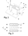
- At least one fin 20, 30 comprises a multi-tupe port with a plurality of channels extending therein. While the channels are not visible in Fig. 1 , they can be seen in Fig. 2 , showing a similar embodiment to that of Fig. 1 , in which the fins 20, 30 are horizontally cut for the purpose of illustration such that the channels 21, 31 can be seen.
- the channels 21, 31 contain a working fluid (not shown) when the heat exchange device is in operation. Due to the working fluid, the channels 21, 31 act as heat pipes. Heat pipes allow heat to be transferred efficiently even over relatively long distances according to the following heat pipe cycle:
- any liquid may be used as the working fluid.
- a working fluid is chosen based on the following criteria:
- Suitable working fluids are e.g. water, glycol, alcohol, other known refrigerants, or mixtures thereof. Also, any other liquid which is compatible with the channel wall material can be used.
- the channels 21, 31 Due to the heat pipe operation, the channels 21, 31 have an improved conduction efficiency. Hence, large amount of heat may be carried over a relatively long distance (also referred to a the fin height), even in the absence of a significant temperature gradient. In some situations, the fin efficiency (heat transport by the fins for some given temperature gradient) may even be more than doubled in comparison to conventional heat sinks with solid fins of same dimensions.
- the above mechanism allows for relatively long fins, especially in the height direction running about perpendicularly to the contact surface of the base 10.
- the fin dimensions are denoted as first dimension L, a second dimension W and a third dimension H, as indicated in Fig. 1 .
- the figures reveal that the fins are aligned with their longest extension with respect to their cross section in the second direction 3, whereas the rows of fins 20, 30 are running in a first direction 2 that is arranged about perpendicularly to the second direction 3 in the horizontal.
- the directions are defined as follows:
- the second direction 3 is defined by the respective row as the direction in which the row extends;
- the first direction 2 is defined by the respective row as the direction orthogonal to the second direction 3 in a plane defined by the rows or by the base 10 surface;
- the third direction 4 is the direction orthogonal to the first and second direction 3 or, put more simply, orthogonal to the surface of the base 10 in a common virtual plane.
- the directions according to these definition may change from fin to fin e.g. in the case of a curved row.
- the channels resides in that a great portion of the metal inside the fins in a conventional full-metal fin is replaced by the working fluid in the heat exchange device according to the present invention, such that the fins according to the present invention are substantially lighter than the conventional ones.
- the fins 20, 30 comprise at least two channels per fin.
- the fins are formed as multi-port tubes having a plurality of parallel elongated channels 21, 31 (preferably in the height, i.e. third dimension H extending in the third direction 4).
- the fins 20, 30 are horizontally cut in order to expose the channels 21,31.
- the multi-port tubes with the parallel channels are aluminum multi-port tubes. They are typically produced using a simple aluminum extrusion process and are hence available at relatively low cost. This is a significant advantage over other more conventional heat pipe systems, where tailored cooling fins/heat pipes where subject to factors like the manufacturability, cooling particularities and limited thermal capacity in terms of height of the fins.
- Using standard multi-tube port profiles contributes essentially to lower overall costs in that the third dimension H of the fins allows for more flexibility of the ever varying factors mentioned above.
- the channels 21, 31 shown have an elongated, strip-like, quasi square cross section.
- any suitable other cross section may be used, as long as the function remains essentially untouched.
- FIGs. 3a to 3c Some examples of further cross sections of the channels 21 are shown in Figs. 3a to 3c.
- Fig. 3a shows again the square cross section of Fig. 2 .
- the inner surface of the channels 21 may comprise fin-like protrusions and / or groove-like recesses.
- the channels 31 of the fins 30 may be formed likewise.
- the latter may comprise one single kind of fins in terms of shape, size and cross section whereas other embodiments feature at least to kind of fins having different cross-sections.
- the cross section of the channels 21, 31 may be either convex (as in Fig. 3a ) or concave (as in Fig. 3b, 3c ).
- the inner channel surface may be substantially smooth (as in Fig. 3a ) or not (as in Fig. 3b, 3c ), "substantially" meaning that edges are disregarded if they define the overall shape of the cross section, such as the corners of the square of Fig. 2 .
- Smooth inner surfaces and / or convex cross sections as in Fig. 3a are suitable e.g. if there is a gravity gradient along the channels (e.g. if the fins are aligned vertically), because then step 4 of the heat pipe cycle (see above) is assisted by gravity acting on the liquid.
- non-smooth inner surfaces and / or concave cross sections and in particular grooved or finned channels as in Figs. 3b, 3c are preferred especially for horizontally aligned fins, because then step 4 may be assisted by capillary pumping provided by the concave structures (e.g. fin-like protrusions and / or groove-like recesses) due to surface tension of the working fluid.
- the at least two channels of one fin comprises different sizes, shapes and/or cross-sections of the channels.
- the fins 20 and 30 and their channels 21, 31 can be of any shape, in particular any shape manufacturable by extrusion. While in Figs. 1 and 2 substantially cuboidic fins are shown, fins of any shape (e.g. cylindrical fins etc) may be used depending on expected air flow and on other geometric constraints. Fin shapes having at least one pair of substantially flat opposite sides in the first direction 2 are somewhat preferred. In Fig. 2 , the channels are shown to be arranged in a linear and/or straight row, but any other arrangement of one or more channels within the fins is also possible.
- the fins are arranged in two different rows, namely in a first row of fins 20 and a second row of fins 30.
- the rows are laterally displaced with respect to each other.
- the fins may be arranged in an m x n matrix with m and n ⁇ 2 (m being a row and n a column of the matrix).
- the first row may be distinguished from the second row in some other manner in addition to or instead of a lateral displacement. Such a distinction may be e.g. based on the size or the shape of the fins.
- the arrangement in a plurality of rows has the following effects: Due to the fins being divided into several rows, the flow of the ambient medium is also subdivided into several zones. The presence of these zones generally may increase the heat transfer from the fins to the ambient medium. This effect is particularly pronounced for a staggered arrangement, as described below. As a further advantage, due to the arrangement in several rows one standard size of fins 20, 30 may be used for different sizes and shapes of the base 10, thus decreasing the number of different components to be stocked, i.e. heat exchange devices having differing key data.
- Figs. 1 and 2 reveals that the first row and second row are staggered with respect to each other.
- staggered is best understood with reference to Fig. 4 , which is an excerpt of a top view of the fins 20, 30 of the heat exchange device of Fig. 1 .
- the respective rows of fins 20 and 30 are indicated by dashed lines.
- the centers of the fins are indicated by solid crosses.
- a lateral projection of the center of the middle fin 30 onto the other row (row of fins 20) is represented by a thick horizontal arrow, whereas the arrow head indicates the projected position of the center onto the other row.
- the projected center i.e.
- the arrow head is positioned, in a longitudinal direction, in between the centers of two neighbouring fins of the other row.
- the projection arrow is orthogonal to both rows (the rows being parallel and running in the first direction 2). Also for curved and / or non-parallel rows, the projection is defined such that the projection arrow is orthogonal to the row section onto which the center is to be projected.
- the fins of the first and second row of another embodiment are staggered in the first direction 2 and alternating in an indenting manner in the second direction 3 such as shown in Figs 1 , 2 and 4 .
- the first and second row are longitudinally offset from one another by a predetermined offset. As shown in Fig. 4 , the offset may be about 0,5, i.e. half of the spacing in the first direction 2 between two neighbouring fin centers of one row.
- the first row is displaced from the second row in the second direction 3 by a predetermined first offset 6, in particular a first offset 6 being at least as long as a fin 20, 30 in its longest extension, and/or in the first direction 2 by a predetermined second offset 7 of about half the distance between two neighbouring fins 20 of the first row.
- the lateral spacing between the rows may be varied as well.
- the first row is substantially laterally displaced from the second row about the first offset 6.
- the first row and the second row have a lateral overlap such that the first and the second row of fins are arranged to one another in a staggered manner in the second direction 3.
- the heat transfer increases due to boundary layer developement.
- the flow is slightly turbulent but close to laminar (the transition between laminar and turbulent being normally in a range of Reynolds numbers from about 2300 to about 10000).
- the length required for the boundary layer to develop is typically longer than heat sink length in the flow direction of the ambient medium. Typical numbers are a length of about 1000 mm for the boundary layer to develop completely, and a heat sink length of 200 mm in the flow direction, that is the second direction 3.
- the heat transfer coefficient would decrease by a factor 3.3 in the flow direction (compared to a fully developed boundary layer). If instead 5 staggered rows of 40 mm fins are used, by means of example, over the 200 mm length, the decrease is be a 1.2 ratio only, hence a much better heat transfer performance than the case of the single row. For the staggered arrangement, a larger pressure drop is required. This requirement can be partially compensated by using a shorter heat sink due to the increased efficiency of the staggered fins.
- the fins 20, 30 can be manufactured by an extrusion process. Subsequently, the channels are filled with the working fluid by any methods known for filling heat pipes. According to one example method, the channels are first evacuated, then the working fluid is filled into the channels, and then the ends of the channels are sealed by any suitable method, e.g. by any method known for the sealing of heat pipes such that the working liquid is prevented from escaping off the heat exchange device. Then, the fins are connected to the base. To this purpose, any assembly method for stacking fins to a base in conventional heat sinks may be used.
- the fins may be provided with an upper portion having the channels and a lower portion being solid, i.e. not having a channel.
- Such fins may be produced as described above, whereby additionally the lower part of the fins is mechanically squeezed such as to make the channel disappear in that part, and whereby optionally material is added to the lower portion (either into the channels before squeezing or to the outside) in order to compensate or overcompensate for any loss in cross-sectional area due to the squeezing.
- the lower portions of the fins can be connected to each other in any suitable manner, whereby the base is formed from these lower portions.
- fins are created whose channels are closed on both ends and hence do not communicate with each other.
- the channels belonging to different fins are fluidly non-communicating with one another.
- the channels 21, 31 of at the at least one first row and the channels 21, 31 of the at least one second row are fluidly disconnected of one another.
- the heat exchange device may comprise still more fins than those described above (e.g. individual fins or a third, fourth, row of fins, etc.).
- the specification and drawings are, accordingly, to be regarded only as illustrations.
Landscapes
- Engineering & Computer Science (AREA)
- Physics & Mathematics (AREA)
- Thermal Sciences (AREA)
- Mechanical Engineering (AREA)
- General Engineering & Computer Science (AREA)
- Life Sciences & Earth Sciences (AREA)
- Sustainable Development (AREA)
- Geometry (AREA)
- Cooling Or The Like Of Semiconductors Or Solid State Devices (AREA)
- Cooling Or The Like Of Electrical Apparatus (AREA)
- Heat-Exchange Devices With Radiators And Conduit Assemblies (AREA)
Priority Applications (1)
| Application Number | Priority Date | Filing Date | Title |
|---|---|---|---|
| EP09158252A EP2112689A3 (fr) | 2008-04-24 | 2009-04-20 | Dispositif d'échange de chaleur |
Applications Claiming Priority (2)
| Application Number | Priority Date | Filing Date | Title |
|---|---|---|---|
| EP08155086 | 2008-04-24 | ||
| EP09158252A EP2112689A3 (fr) | 2008-04-24 | 2009-04-20 | Dispositif d'échange de chaleur |
Publications (2)
| Publication Number | Publication Date |
|---|---|
| EP2112689A2 true EP2112689A2 (fr) | 2009-10-28 |
| EP2112689A3 EP2112689A3 (fr) | 2012-06-13 |
Family
ID=39757638
Family Applications (1)
| Application Number | Title | Priority Date | Filing Date |
|---|---|---|---|
| EP09158252A Withdrawn EP2112689A3 (fr) | 2008-04-24 | 2009-04-20 | Dispositif d'échange de chaleur |
Country Status (3)
| Country | Link |
|---|---|
| US (1) | US20090266514A1 (fr) |
| EP (1) | EP2112689A3 (fr) |
| CN (1) | CN101566443A (fr) |
Cited By (2)
| Publication number | Priority date | Publication date | Assignee | Title |
|---|---|---|---|---|
| DE102011118483A1 (de) | 2011-11-12 | 2013-05-16 | Volkswagen Aktiengesellschaft | Wärmeübertrager |
| EP3144625A1 (fr) * | 2015-09-21 | 2017-03-22 | ABB Schweiz AG | Ensemble de refroidissement et son procédé de fabrication |
Families Citing this family (15)
| Publication number | Priority date | Publication date | Assignee | Title |
|---|---|---|---|---|
| US7761783B2 (en) * | 2007-01-19 | 2010-07-20 | Microsoft Corporation | Document performance analysis |
| CN102163757A (zh) * | 2010-02-23 | 2011-08-24 | 通用汽车环球科技运作有限责任公司 | 用于空冷锂离子电池和电池组的热管与百叶窗翅片的组合 |
| US20130114204A1 (en) * | 2011-11-04 | 2013-05-09 | Apple Inc. | Heat removal system for computing systems |
| CN103994686A (zh) * | 2014-05-27 | 2014-08-20 | 天津大学 | 一种新型高效低压降的板翅式换热器翅片 |
| CN103994687A (zh) * | 2014-05-27 | 2014-08-20 | 天津大学 | 新型高效的板翅式换热器翅片 |
| CN103994685A (zh) * | 2014-05-27 | 2014-08-20 | 天津大学 | 一种新型板翅式换热器翅片 |
| CN105318753A (zh) * | 2014-06-17 | 2016-02-10 | 珠海兴业新能源科技有限公司 | 独立相变传热式抗冻防腐热管 |
| US20160047604A1 (en) * | 2014-08-15 | 2016-02-18 | Ge Aviation Systems Llc | Heat dissipating assembly |
| WO2016123912A1 (fr) * | 2015-02-03 | 2016-08-11 | 冯伶 | Radiateur de chauffage du type à plaque d'acier ultra-mince |
| CN105588229A (zh) * | 2015-02-15 | 2016-05-18 | 海信(山东)空调有限公司 | 一种散热器及空调器 |
| EP3115728B1 (fr) * | 2015-07-09 | 2019-05-01 | ABB Schweiz AG | Appareil et procédé de refroidissement |
| US10694641B2 (en) * | 2016-04-29 | 2020-06-23 | Intel Corporation | Wickless capillary driven constrained vapor bubble heat pipes for application in electronic devices with various system platforms |
| JP6938138B2 (ja) * | 2016-11-28 | 2021-09-22 | キヤノン株式会社 | 電子機器 |
| CN107060966A (zh) * | 2017-01-25 | 2017-08-18 | 清华大学苏州汽车研究院(相城) | 一种适用于尾气热电回收的集热器 |
| US11421945B1 (en) * | 2020-06-25 | 2022-08-23 | Softronics, Ltd. | Heat dissipation system with cross-connected heatsink |
Citations (1)
| Publication number | Priority date | Publication date | Assignee | Title |
|---|---|---|---|---|
| US7150312B2 (en) | 2001-11-27 | 2006-12-19 | Thermotek, Inc. | Stacked low profile cooling system and method for making same |
Family Cites Families (15)
| Publication number | Priority date | Publication date | Assignee | Title |
|---|---|---|---|---|
| DE4121534C2 (de) * | 1990-06-30 | 1998-10-08 | Toshiba Kawasaki Kk | Kühlvorrichtung |
| US5253702A (en) * | 1992-01-14 | 1993-10-19 | Sun Microsystems, Inc. | Integral heat pipe, heat exchanger, and clamping plate |
| JPH05243441A (ja) * | 1992-03-03 | 1993-09-21 | Ito Gijutsu Kenkiyuushitsu:Kk | 放熱装置 |
| JPH0731027B2 (ja) * | 1992-09-17 | 1995-04-10 | 伊藤 さとみ | ヒートパイプおよび放熱装置 |
| JPH07243782A (ja) * | 1994-03-02 | 1995-09-19 | Hitachi Ltd | ヒートパイプ式放熱器 |
| JPH10154781A (ja) * | 1996-07-19 | 1998-06-09 | Denso Corp | 沸騰冷却装置 |
| EP0889524A3 (fr) * | 1997-06-30 | 1999-03-03 | Sun Microsystems, Inc. | Système de refroidissement échelonnable et modulaire de type dissipateur de chaleur-caloduc |
| TW556328B (en) * | 2001-05-11 | 2003-10-01 | Denso Corp | Cooling device boiling and condensing refrigerant |
| US6595270B2 (en) * | 2001-06-29 | 2003-07-22 | Intel Corporation | Using micro heat pipes as heat exchanger unit for notebook applications |
| JP3918502B2 (ja) * | 2001-10-25 | 2007-05-23 | 株式会社デンソー | 沸騰冷却装置 |
| JP2004125381A (ja) * | 2002-08-02 | 2004-04-22 | Mitsubishi Alum Co Ltd | ヒートパイプユニット及びヒートパイプ冷却器 |
| US20040112572A1 (en) * | 2002-12-17 | 2004-06-17 | Moon Seok Hwan | Micro heat pipe with poligonal cross-section manufactured via extrusion or drawing |
| US7106589B2 (en) * | 2003-12-23 | 2006-09-12 | Aall Power Heatsinks, Inc. | Heat sink, assembly, and method of making |
| US20050135061A1 (en) * | 2003-12-23 | 2005-06-23 | Richard Kiley | Heat sink, assembly, and method of making |
| TWM317745U (en) * | 2007-02-13 | 2007-08-21 | Bothhand Entpr Inc | Improved structure of heat sink |
-
2009
- 2009-04-20 US US12/426,482 patent/US20090266514A1/en not_active Abandoned
- 2009-04-20 EP EP09158252A patent/EP2112689A3/fr not_active Withdrawn
- 2009-04-24 CN CNA2009101321494A patent/CN101566443A/zh active Pending
Patent Citations (1)
| Publication number | Priority date | Publication date | Assignee | Title |
|---|---|---|---|---|
| US7150312B2 (en) | 2001-11-27 | 2006-12-19 | Thermotek, Inc. | Stacked low profile cooling system and method for making same |
Cited By (3)
| Publication number | Priority date | Publication date | Assignee | Title |
|---|---|---|---|---|
| DE102011118483A1 (de) | 2011-11-12 | 2013-05-16 | Volkswagen Aktiengesellschaft | Wärmeübertrager |
| EP3144625A1 (fr) * | 2015-09-21 | 2017-03-22 | ABB Schweiz AG | Ensemble de refroidissement et son procédé de fabrication |
| US10077947B2 (en) | 2015-09-21 | 2018-09-18 | Abb Schweiz Ag | Cooling assembly and method for manufacturing the same |
Also Published As
| Publication number | Publication date |
|---|---|
| US20090266514A1 (en) | 2009-10-29 |
| CN101566443A (zh) | 2009-10-28 |
| EP2112689A3 (fr) | 2012-06-13 |
Similar Documents
| Publication | Publication Date | Title |
|---|---|---|
| US20090266514A1 (en) | Heat exchange device | |
| CN100470776C (zh) | 吸热器 | |
| US20180080685A1 (en) | Microelectronics cooling system | |
| EP2568789B1 (fr) | Échangeur de chaleur | |
| KR100606283B1 (ko) | 히트 파이프 유니트 및, 히트 파이프 유형의 열교환기 | |
| CN106338211B (zh) | 热交换器 | |
| EP3144625B1 (fr) | Ensemble de refroidissement et son procédé de fabrication | |
| CN103759563A (zh) | 一种利用工质相变循环运动传热的微通道散热装置 | |
| US20100326627A1 (en) | Microelectronics cooling system | |
| JP2017531154A (ja) | 貯留機能を備えた平面型ヒートパイプ | |
| CN102573407A (zh) | 热交换器 | |
| CN102315500A (zh) | 电池组 | |
| CN106052444B (zh) | 一种平板热管阵列式散热器 | |
| US20140352927A1 (en) | Apparatus | |
| CN102202488A (zh) | 热管散热装置 | |
| CN111741650A (zh) | 热超导散热板、散热器及5g基站设备 | |
| US11859912B2 (en) | Microelectronics cooling system | |
| CN101742890A (zh) | 散热装置 | |
| CN115052461A (zh) | 一种脉动热管散热装置及散热系统 | |
| CN110411258A (zh) | 一种用于cpu散热的重力环路热管散热器 | |
| CN215453789U (zh) | 散热器 | |
| CN116193813A (zh) | 一种三维相变散热器 | |
| CN116568985A (zh) | 热存储装置 | |
| CN205991730U (zh) | 一种平板热管阵列式散热器 | |
| CN108323099B (zh) | 翅片式热管耦合散热器 |
Legal Events
| Date | Code | Title | Description |
|---|---|---|---|
| PUAI | Public reference made under article 153(3) epc to a published international application that has entered the european phase |
Free format text: ORIGINAL CODE: 0009012 |
|
| AK | Designated contracting states |
Kind code of ref document: A2 Designated state(s): AT BE BG CH CY CZ DE DK EE ES FI FR GB GR HR HU IE IS IT LI LT LU LV MC MK MT NL NO PL PT RO SE SI SK TR |
|
| 17P | Request for examination filed |
Effective date: 20100414 |
|
| PUAL | Search report despatched |
Free format text: ORIGINAL CODE: 0009013 |
|
| AK | Designated contracting states |
Kind code of ref document: A3 Designated state(s): AT BE BG CH CY CZ DE DK EE ES FI FR GB GR HR HU IE IS IT LI LT LU LV MC MK MT NL NO PL PT RO SE SI SK TR |
|
| RIC1 | Information provided on ipc code assigned before grant |
Ipc: H01L 23/427 20060101AFI20120508BHEP |
|
| STAA | Information on the status of an ep patent application or granted ep patent |
Free format text: STATUS: THE APPLICATION IS DEEMED TO BE WITHDRAWN |
|
| 18D | Application deemed to be withdrawn |
Effective date: 20121214 |