EP2112704A1 - Batteriepack - Google Patents
Batteriepack Download PDFInfo
- Publication number
- EP2112704A1 EP2112704A1 EP09290143A EP09290143A EP2112704A1 EP 2112704 A1 EP2112704 A1 EP 2112704A1 EP 09290143 A EP09290143 A EP 09290143A EP 09290143 A EP09290143 A EP 09290143A EP 2112704 A1 EP2112704 A1 EP 2112704A1
- Authority
- EP
- European Patent Office
- Prior art keywords
- protection circuit
- battery pack
- cap plate
- bare cell
- case
- Prior art date
- Legal status (The legal status is an assumption and is not a legal conclusion. Google has not performed a legal analysis and makes no representation as to the accuracy of the status listed.)
- Withdrawn
Links
Images




Classifications
-
- H—ELECTRICITY
- H01—ELECTRIC ELEMENTS
- H01M—PROCESSES OR MEANS, e.g. BATTERIES, FOR THE DIRECT CONVERSION OF CHEMICAL ENERGY INTO ELECTRICAL ENERGY
- H01M50/00—Constructional details or processes of manufacture of the non-active parts of electrochemical cells other than fuel cells, e.g. hybrid cells
- H01M50/10—Primary casings; Jackets or wrappings
- H01M50/147—Lids or covers
- H01M50/166—Lids or covers characterised by the methods of assembling casings with lids
- H01M50/169—Lids or covers characterised by the methods of assembling casings with lids by welding, brazing or soldering
-
- H—ELECTRICITY
- H01—ELECTRIC ELEMENTS
- H01M—PROCESSES OR MEANS, e.g. BATTERIES, FOR THE DIRECT CONVERSION OF CHEMICAL ENERGY INTO ELECTRICAL ENERGY
- H01M10/00—Secondary cells; Manufacture thereof
- H01M10/05—Accumulators with non-aqueous electrolyte
- H01M10/058—Construction or manufacture
-
- H—ELECTRICITY
- H01—ELECTRIC ELEMENTS
- H01M—PROCESSES OR MEANS, e.g. BATTERIES, FOR THE DIRECT CONVERSION OF CHEMICAL ENERGY INTO ELECTRICAL ENERGY
- H01M10/00—Secondary cells; Manufacture thereof
- H01M10/42—Methods or arrangements for servicing or maintenance of secondary cells or secondary half-cells
- H01M10/425—Structural combination with electronic components, e.g. electronic circuits integrated to the outside of the casing
-
- H—ELECTRICITY
- H01—ELECTRIC ELEMENTS
- H01M—PROCESSES OR MEANS, e.g. BATTERIES, FOR THE DIRECT CONVERSION OF CHEMICAL ENERGY INTO ELECTRICAL ENERGY
- H01M50/00—Constructional details or processes of manufacture of the non-active parts of electrochemical cells other than fuel cells, e.g. hybrid cells
- H01M50/10—Primary casings; Jackets or wrappings
- H01M50/147—Lids or covers
-
- H—ELECTRICITY
- H01—ELECTRIC ELEMENTS
- H01M—PROCESSES OR MEANS, e.g. BATTERIES, FOR THE DIRECT CONVERSION OF CHEMICAL ENERGY INTO ELECTRICAL ENERGY
- H01M50/00—Constructional details or processes of manufacture of the non-active parts of electrochemical cells other than fuel cells, e.g. hybrid cells
- H01M50/10—Primary casings; Jackets or wrappings
- H01M50/172—Arrangements of electric connectors penetrating the casing
-
- H—ELECTRICITY
- H01—ELECTRIC ELEMENTS
- H01M—PROCESSES OR MEANS, e.g. BATTERIES, FOR THE DIRECT CONVERSION OF CHEMICAL ENERGY INTO ELECTRICAL ENERGY
- H01M50/00—Constructional details or processes of manufacture of the non-active parts of electrochemical cells other than fuel cells, e.g. hybrid cells
- H01M50/10—Primary casings; Jackets or wrappings
- H01M50/172—Arrangements of electric connectors penetrating the casing
- H01M50/174—Arrangements of electric connectors penetrating the casing adapted for the shape of the cells
- H01M50/176—Arrangements of electric connectors penetrating the casing adapted for the shape of the cells for prismatic or rectangular cells
-
- H—ELECTRICITY
- H01—ELECTRIC ELEMENTS
- H01M—PROCESSES OR MEANS, e.g. BATTERIES, FOR THE DIRECT CONVERSION OF CHEMICAL ENERGY INTO ELECTRICAL ENERGY
- H01M50/00—Constructional details or processes of manufacture of the non-active parts of electrochemical cells other than fuel cells, e.g. hybrid cells
- H01M50/20—Mountings; Secondary casings or frames; Racks, modules or packs; Suspension devices; Shock absorbers; Transport or carrying devices; Holders
-
- H—ELECTRICITY
- H01—ELECTRIC ELEMENTS
- H01M—PROCESSES OR MEANS, e.g. BATTERIES, FOR THE DIRECT CONVERSION OF CHEMICAL ENERGY INTO ELECTRICAL ENERGY
- H01M50/00—Constructional details or processes of manufacture of the non-active parts of electrochemical cells other than fuel cells, e.g. hybrid cells
- H01M50/50—Current conducting connections for cells or batteries
- H01M50/572—Means for preventing undesired use or discharge
- H01M50/574—Devices or arrangements for the interruption of current
- H01M50/579—Devices or arrangements for the interruption of current in response to shock
-
- H—ELECTRICITY
- H01—ELECTRIC ELEMENTS
- H01M—PROCESSES OR MEANS, e.g. BATTERIES, FOR THE DIRECT CONVERSION OF CHEMICAL ENERGY INTO ELECTRICAL ENERGY
- H01M2200/00—Safety devices for primary or secondary batteries
-
- H—ELECTRICITY
- H01—ELECTRIC ELEMENTS
- H01M—PROCESSES OR MEANS, e.g. BATTERIES, FOR THE DIRECT CONVERSION OF CHEMICAL ENERGY INTO ELECTRICAL ENERGY
- H01M50/00—Constructional details or processes of manufacture of the non-active parts of electrochemical cells other than fuel cells, e.g. hybrid cells
- H01M50/10—Primary casings; Jackets or wrappings
- H01M50/102—Primary casings; Jackets or wrappings characterised by their shape or physical structure
- H01M50/103—Primary casings; Jackets or wrappings characterised by their shape or physical structure prismatic or rectangular
-
- H—ELECTRICITY
- H01—ELECTRIC ELEMENTS
- H01M—PROCESSES OR MEANS, e.g. BATTERIES, FOR THE DIRECT CONVERSION OF CHEMICAL ENERGY INTO ELECTRICAL ENERGY
- H01M50/00—Constructional details or processes of manufacture of the non-active parts of electrochemical cells other than fuel cells, e.g. hybrid cells
- H01M50/50—Current conducting connections for cells or batteries
- H01M50/572—Means for preventing undesired use or discharge
- H01M50/584—Means for preventing undesired use or discharge for preventing incorrect connections inside or outside the batteries
- H01M50/59—Means for preventing undesired use or discharge for preventing incorrect connections inside or outside the batteries characterised by the protection means
- H01M50/593—Spacers; Insulating plates
-
- Y—GENERAL TAGGING OF NEW TECHNOLOGICAL DEVELOPMENTS; GENERAL TAGGING OF CROSS-SECTIONAL TECHNOLOGIES SPANNING OVER SEVERAL SECTIONS OF THE IPC; TECHNICAL SUBJECTS COVERED BY FORMER USPC CROSS-REFERENCE ART COLLECTIONS [XRACs] AND DIGESTS
- Y02—TECHNOLOGIES OR APPLICATIONS FOR MITIGATION OR ADAPTATION AGAINST CLIMATE CHANGE
- Y02E—REDUCTION OF GREENHOUSE GAS [GHG] EMISSIONS, RELATED TO ENERGY GENERATION, TRANSMISSION OR DISTRIBUTION
- Y02E60/00—Enabling technologies; Technologies with a potential or indirect contribution to GHG emissions mitigation
- Y02E60/10—Energy storage using batteries
-
- Y—GENERAL TAGGING OF NEW TECHNOLOGICAL DEVELOPMENTS; GENERAL TAGGING OF CROSS-SECTIONAL TECHNOLOGIES SPANNING OVER SEVERAL SECTIONS OF THE IPC; TECHNICAL SUBJECTS COVERED BY FORMER USPC CROSS-REFERENCE ART COLLECTIONS [XRACs] AND DIGESTS
- Y02—TECHNOLOGIES OR APPLICATIONS FOR MITIGATION OR ADAPTATION AGAINST CLIMATE CHANGE
- Y02P—CLIMATE CHANGE MITIGATION TECHNOLOGIES IN THE PRODUCTION OR PROCESSING OF GOODS
- Y02P70/00—Climate change mitigation technologies in the production process for final industrial or consumer products
- Y02P70/50—Manufacturing or production processes characterised by the final manufactured product
Definitions
- the present invention relates to a battery pack, and more particularly, to a battery pack which can prevent easy detachment of a welded part between a cap plate and a case due to external impact, thereby enhancing hermeticity and reliability.
- Secondary batteries are rechargeable and can be repeatedly used. Thus, secondary batteries are more economical than disposable batteries.
- the secondary batteries can realize high capacity with small volume, so that they are widely used as a driving power source for handheld electronic devices such as cellular phones, notebook computers, camcorders and digital cameras.
- the secondary batteries are widely used in high power products such as hybrid cars and electric tools as well as handheld electrical appliances.
- Such secondary batteries include, for example, nickel-cadmium batteries, nickel-metal hydride batteries, nickel-zinc batteries, lithium ion secondary batteries and lithium polymer secondary batteries.
- the lithium secondary batteries are widely used because they are compact and have high capacity, a high operating voltage and a high energy density per unit weight.
- the lithium secondary batteries are formed by accommodating an electrode assembly and an electrolyte in a case and sealing the case.
- the lithium secondary batteries may be classified into a can type and a pouch type depending on the shape of the case, and the can-type batteries may be classified into a cylindrical type and a rectangular type.
- the rectangular-type lithium secondary battery is formed by accommodating an electrode assembly including a positive electrode plate, a negative electrode plate and a separator in a rectangular-type case having an opening at one side, and sealing the opening using a cap assembly.
- the cap assembly includes a cap plate disposed at an opening of the case, and an electrode terminal inserted into in the middle of the cap plate.
- the case is sealed by welding an edge of the cap plate disposed at the opening using laser to join the cap plate with the case.
- the rectangular-type secondary battery has the electrode terminal in the middle of the cap plate, the welded part between the cap plate and the case can be easily detached from each other when external impact caused, for example, by the battery being dropped, is concentrated in a part where the electrode terminal is disposed.
- the hole part of the cap plate is more vulnerable to the external impact.
- aspects of the present invention provide a battery pack which inhibits detachment of a welded part between a cap plate and a case due to external impact, thereby enhancing hermeticity and reliability.
- a battery pack includes: a bare cell; and a protection circuit assembly electrically connected with the bare cell and including a protection circuit board, wherein the protection circuit board includes a protection circuit module, and the protection circuit module is in contact with the bare cell.
- the bare cell may include a case having an opening at one side and a cap assembly sealing the case.
- the cap assembly may include a cap plate coupled to the opening, and edges of the cap plate and the opening may be welded to each other.
- the case may include narrow side surfaces facing each other and wide side surfaces facing each other, these side surfaces being laterally connected with each other, and a first surface and a second surface formed by being surrounded by the side surfaces.
- a distance between the narrow side surfaces facing each other may be larger than a distance between the first and second surfaces.
- the protection circuit board may include a printed circuit board, and a protection circuit, a PTC thermistor, an external connection terminal and a connection terminal which are mounted on the printed circuit board, and the protection circuit module may be formed by covering the protection circuit and the PTC thermistor using an encapsulating part.
- the encapsulating part may be in contact with the cap plate.
- the protection circuit module may be disposed in a middle part of the protection circuit board.
- the bare cell may include a welded part formed by welding an edge of the cap plate and an edge of the opening of the case, and the protection circuit module may be disposed on an upper surface of an edge of the cap plate corresponding to the welded part.
- the protection circuit module may be disposed in the middle part of the cap plate.
- the cap plate may include a terminal through-hole, which is eccentrically disposed with respect to a center of the cap plate.
- the terminal through-hole may be spaced 1/2 to 3/4 apart from the center of the cap plate in a major axis direction.
- a battery pack includes a bare cell including a case accommodating an electrode assembly and having an opening at one side and a cap assembly sealing the case, and a protection circuit assembly electrically connected with the bare cell.
- the case includes narrow side surfaces facing each other and wide side surfaces facing each other, these surfaces being laterally connected with each other, and first and second surfaces formed by being surrounded by the side surfaces.
- the cap assembly is coupled to the opening and includes a cap plate having a terminal through-hole, a distance between the narrow side surfaces facing each other is larger than a distance between the first and second surfaces, and the terminal through-hole is eccentrically disposed with respect to a center of the cap plate.
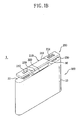
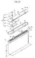
- FIGS. 1A and 1B are exploded and assembled perspective views of a battery pack according to an exemplary embodiment of the present invention, respectively, and FIG. 1C is a front view of the battery pack of FIG. 1B .
- FIG. 2A is an exploded perspective view of a bare cell included in a battery pack according to an exemplary embodiment of the present invention
- FIG. 2B is an assembled cross-sectional view of the bare cell of FIG. 2A .
- the bare cell 100 includes a case 10, an electrode assembly 20 accommodated in the case 10, and a cap assembly 30 sealing the case 10.
- the bare cell 100 further includes an insulating case 40 disposed on the electrode assembly 20 accommodated in the case 10.
- the bare cell 100 further includes an electrolyte accommodated in the case 10 to help the current flow.
- the case 10 may form an appearance of the bare cell 100, which may be formed in a rectangular shape or a rectangular shape having rounded corners, but the present invention is not limited thereto.
- one side of the case 10 has an opening for inserting the electrode assembly 20 into the case 10.
- the case 10 includes narrow side surfaces facing each other and wide side surfaces facing each other, which are connected with each other.
- a first surface is open to insert the electrode assembly 20 into the case 10, and a second surface is closed.
- the open first surface is called a top surface of the case 10
- the close second surface is called a bottom surface of the case 10.
- a lateral width W1 of the bare cell 100 is a distance between the narrow side surfaces facing each other, and a longitudinal width W2 of the bare cell 100 is a distance between the top surface and the bottom surface.
- the lateral width W1 is larger than the longitudinal width W2.
- the case 10 may be formed of a metallic material, for example, one selected from aluminum, an aluminum alloy, stainless steel and equivalents thereof.
- the electrode assembly 20 includes a first electrode plate 21 and a second electrode plate 23, which have different polarities from each other.
- the electrode assembly 20 further includes a separator 25 interposed between the first and second electrode plates 21 and 23, and the separator 25 prevents a short circuit between the two electrode plates 21 and 23.
- the first electrode plate 21 is called a positive electrode plate
- the second electrode plate 23 is called a negative electrode plate.
- the positive electrode plate 21 is formed by applying a slurry containing a positive electrode active material to a positive electrode collector
- the negative electrode plate 23 is formed by applying a slurry containing a negative electrode active material to a negative electrode collector.
- Each of the positive and negative electrode plates 21 and 23 includes a non-coated portion to which an active material is not applied, and each electrode tab 27 or 29 is attached to the non-coating portion to be electrically connected.
- first electrode tab 27 is electrically connected with the positive electrode plate 21
- second electrode tab 29 is electrically connected with the negative electrode plate 23.
- the first electrode tab 27 is called a positive electrode tab
- the second electrode tab 29 is called a negative electrode tab.
- the cap assembly 30 may include a cap plate 31, an insulating gasket 32, an electrode terminal 33, an insulating plate 34, a terminal plate 35 and an electrolyte inlet plug 36.
- the cap plate 31 is disposed at an opening of the case 10 and an edge 31d of the cap plate 31 is joined with an edge 11 of the opening of the case 10 by welding, e.g. laser welding, thereby sealing the case 10.
- the bare cell 100 includes a welded part 50 formed by welding an edge 31d of the cap plate 31 and an edge 11 of the opening of the case 10, and the case 10 and the cap plate 31 are fixed by the welded part 50.
- the cap plate 31 includes a terminal through-hole 31a into which the insulating gasket 32 and the electrode terminal 33 are inserted, and an electrolyte inlet 31b serving as a passage for electrolyte injection.
- the terminal through-hole 31a may be eccentrically disposed with respect to the center of the cap plate 31, and may be formed adjacent to an end in a major axis direction.
- the electrode terminal 33 coupled to the terminal through-hole 31a is also eccentrically disposed with respect to the center of the cap plate 31, and a space is formed in the middle of the cap plate 31.
- a protection circuit 212 and a PTC 213 covered by an encapsulating part 218 to be described later, i.e., a protection circuit module 219 is disposed.
- the terminal through-hole 31a may be spaced from the approximate center of the cap plate 1/2 to 3/4 of the distance of the cap plate 31 from the approximate center to the approximate end of the cap plate 31 in the major axis direction.
- the electrode terminal 33 is also disposed adjacent to the end of the cap plate 31 in the major axis direction, so that impact applied to the electrode terminal 33 can be scattered as compared with when the electrode terminal 33 is disposed in the middle of the cap plate 31.
- the cap plate 31 may include a vent 31c which is broken to exhaust a gas when inner pressure of the bare cell 100 is increased, and the vent 31c may include a notch part to facilitate the breakage of the vent 31c.
- the insulating gasket 32 is coupled to the terminal through-hole 31 a formed in the cap plate 31, and insulates the electrode terminal 33 from the cap plate 31.
- the insulating gasket 32 has a hole in the middle part, and the electrode terminal 33 is positioned in the hole.
- a lower part of the electrode terminal 33 is electrically connected with the terminal plate 35 through the cap plate 31.
- the insulating plate 34 is disposed under the cap plate 31, and insulates the terminal plate 35 from the cap plate 31.
- the insulating plate 34 has a hole to connect the terminal plate 35 with the electrode terminal 33.
- the terminal plate 35 is disposed under the insulating plate 34, and connected with the electrode terminal 33 to form an electrical path.
- the positive electrode tab 27 is electrically connected with a bottom surface of the cap plate 31, and the negative electrode tab 29 is electrically connected with a bottom surface of the terminal plate 35.
- the insulating case 40 is disposed on the electrode assembly 20 accommodated in the case 10 to prevent movement of the electrode assembly 20.
- the insulating case 40 includes a tab groove 41 and a tab hole 42, both of which separate the positive electrode tab 27 a predetermined distance from the negative electrode tab 29 to prevent a short circuit therebetween and serve as guides when the positive and negative electrode tabs 27 and 29 project through the insulating case 40.
- the insulating case 40 may further include an injection hole 43 formed to provide a passage for smooth injection of the electrolyte into the electrode assembly 20.
- a battery pack 1 according to an exemplary embodiment of the present invention includes a bare cell 100 and a protection circuit assembly 200, which are electrically connected with each other.
- the bare cell 100 is sealed by joining an open top surface of the case 10 with the cap assembly 30.
- the top surface of the case 10 coupled to the cap assembly 30 is called a top surface of the bare cell 100, and the protection circuit assembly 200 may be disposed on the top surface of the bare cell 100.
- the electrode terminal 33 is disposed adjacent to an end of the bare cell 100 in a major axis direction.
- FIG. 3 is an assembled cross-sectional view of a protection circuit assembly according to an exemplary embodiment of the present invention.
- the protection circuit assembly 200 includes a protection circuit board 210, and lead plates having a first lead plate 230 and a second lead plate 250 for electrical connection between the protection circuit board 210 and the bare cell 100.
- the protection circuit board 210 may be formed by mounting a protection circuit 212, a PTC thermistor 213, an external connection terminal 214, and connection terminals having a first connection terminal 215 and a second connection terminal 216 for connecting the lead plates 230 and 250 on a printed circuit board 211.
- the protection circuit board 210 further includes a terminal hole 217 formed at a location corresponding to the electrode terminal 33 of the bare cell 100, and the terminal hole 217 may be formed adjacent to an end of a long side of the printed circuit board 211.
- the protection circuit 212 and the PTC thermistor 213 are disposed in a middle region of the protection circuit board 210, and covered by an encapsulating part 218.
- a protection circuit module 219 is formed by covering the protection circuit 212 and the PTC thermistor 213 using the encapsulating part 218.
- the encapsulating part 218 may be formed of resin, for example, an organic material including a hardener and epoxy forming a three-dimensional hardening structure by being hardened due to heat, or an organic-inorganic combination material to improve mechanical and electrical performance.
- the protection circuit 212 may include a circuit for controlling charge and discharge of the bare cell 100, a circuit for controlling an abnormal operation such as overcharge, overdischarge or overcurrent, and a smart circuit for providing information including available time, remaining charge time, remaining charge amount and life span of the bare cell 100.
- a lower end of the protection circuit module 219 is in contact with the cap plate 31 of the bare cell 100.
- the protection circuit module 219 may be disposed on an upper surface of the edge 31d of the cap plate 31 corresponding to the welded part 50 formed in the edge 31d of the cap plate 31 and the edge 11 of the opening of the case 10.
- the encapsulating part 218 may be disposed on the upper surface of the edge 31 d of the cap plate 31 corresponding to the welded part 50.
- the protection circuit module 219 serves as a support, which thus may inhibit detachment of the welded part 50.
- the first lead plate 230 is connected with the first connection terminal 215 and exposed outside through the terminal hole 217, and the second lead plate 250 is connected with the second connection terminal 216.
- the first lead plate 230 is connected with the electrode terminal 33, and the second lead plate 250 is connected with the cap plate 31, so that the bare cell 100 is electrically connected with the protection circuit assembly 200.
- Table 1 shows results of a free drop test for a conventional battery pack and a battery pack according to the exemplary embodiment of the present invention, in both of which a case and a cap plate are welded with an equal weld depth.
- Cycle Weld Depth ( ⁇ m) Free Drop Test Comparative Example Embodiment 1 225 300 500 2 237 400 500 3 238 400 500 4 242 400 500 5 244 400 500 6 246 400 600 7 247 500 600 8 256 500 600 9 257 500 600 10 259 500 600 11 265 500 600 12 267 500 600 13 269 500 600 14 271 500 600 15 273 500 600 16 275 500 700 17 283 500 700 18 285 500 600 19 292 600 700 20 296 600 800 21 297 600 800
- the battery pack in the present embodiment shows a better characteristic than that in the comparative example in the free drop test.
- the battery pack in the present embodiment generally shows a better characteristic in the free drop test.
- the larger output can damage an insulating case and an electrode assembly.
- the battery pack 1 may further include a shock-absorber 300 disposed between the cap plate 31 and the protection circuit module 219.
- the shock-absorber 300 may be disposed to cover the welded part to reduce impact applied to the welded part between the case 10 and the cap plate 31.
- the shock-absorber 300 may be a double-sided adhesive tape, and may improve adhesive strength between the cap plate 31 and the protection circuit module 219.
- the battery pack 1 formed as such may further include a hard case accommodating the bare cell 100 and the protection circuit assembly 200.
- the battery pack 1 may be subjected to tubing and labeling to cover the bare cell 100 and the protection circuit assembly 200 while the protection circuit assembly 200 is covered by an upper cover.
- a protection circuit module is in contact with a bare cell, and thus external impact applied to a welded part between a cap plate and a case can be reduced.
- an electrode terminal may be disposed adjacent to an end of the bare cell in a major axis direction, thereby dispersing the impact applied to the welded part between the cap plate and the case. Thus, easy detachment of the cap plate from the case due to external impact can be prevented.
- the welded part is not easily detached, thereby enhancing hermeticity and reliability.
Landscapes
- Chemical & Material Sciences (AREA)
- Chemical Kinetics & Catalysis (AREA)
- Electrochemistry (AREA)
- General Chemical & Material Sciences (AREA)
- Engineering & Computer Science (AREA)
- Manufacturing & Machinery (AREA)
- Microelectronics & Electronic Packaging (AREA)
- Battery Mounting, Suspending (AREA)
- Sealing Battery Cases Or Jackets (AREA)
- Connection Of Batteries Or Terminals (AREA)
Applications Claiming Priority (1)
| Application Number | Priority Date | Filing Date | Title |
|---|---|---|---|
| KR1020080038275A KR101004401B1 (ko) | 2008-04-24 | 2008-04-24 | 배터리 팩 |
Publications (1)
| Publication Number | Publication Date |
|---|---|
| EP2112704A1 true EP2112704A1 (de) | 2009-10-28 |
Family
ID=40714973
Family Applications (1)
| Application Number | Title | Priority Date | Filing Date |
|---|---|---|---|
| EP09290143A Withdrawn EP2112704A1 (de) | 2008-04-24 | 2009-02-27 | Batteriepack |
Country Status (5)
| Country | Link |
|---|---|
| US (1) | US8846221B2 (de) |
| EP (1) | EP2112704A1 (de) |
| JP (1) | JP5121751B2 (de) |
| KR (1) | KR101004401B1 (de) |
| CN (1) | CN101567431B (de) |
Cited By (3)
| Publication number | Priority date | Publication date | Assignee | Title |
|---|---|---|---|---|
| WO2014023480A1 (de) * | 2012-08-10 | 2014-02-13 | Robert Bosch Gmbh | Gehäuse für eine batteriezelle mit einem gehäusedeckel eine überwachungselektronik aufweisend, batteriezelle, batteriemodul sowie kraftfahrzeug |
| EP2424004A3 (de) * | 2010-08-24 | 2014-04-30 | Samsung SDI Co., Ltd. | Wiederaufladbare Batterie |
| DE102013213551A1 (de) * | 2013-07-11 | 2015-01-15 | Robert Bosch Gmbh | Aufnahmevorrichtung, Batterie und Kraftfahrzeug |
Families Citing this family (13)
| Publication number | Priority date | Publication date | Assignee | Title |
|---|---|---|---|---|
| US8481183B2 (en) * | 2008-12-23 | 2013-07-09 | Samsung Sdi Co., Ltd. | Secondary battery |
| KR101106324B1 (ko) * | 2010-01-12 | 2012-01-18 | 삼성에스디아이 주식회사 | 파우치형 전지 |
| KR101126809B1 (ko) * | 2010-06-16 | 2012-03-23 | 에스비리모티브 주식회사 | 이차 전지 |
| US9818990B2 (en) * | 2010-08-27 | 2017-11-14 | Samsung Sdi Co., Ltd. | Battery pack with shock absorber |
| KR101175014B1 (ko) * | 2010-10-18 | 2012-08-17 | 에스비리모티브 주식회사 | 이차 전지 |
| KR101905081B1 (ko) * | 2011-12-09 | 2018-11-30 | 삼성에스디아이 주식회사 | 배터리 팩 |
| KR20130104489A (ko) * | 2012-03-14 | 2013-09-25 | 삼성에스디아이 주식회사 | 연결부재, 이를 구비한 배터리 팩 및 그 제조방법 |
| DE102013206636A1 (de) * | 2013-04-15 | 2014-10-16 | Robert Bosch Gmbh | Batteriezelle mit einem aus mindestens zwei Teilen bestehenden Deckel sowie ein Verfahren zur Herstellung einer Batteriezelle |
| CN105047833B (zh) * | 2015-06-02 | 2018-12-21 | 星恒电源股份有限公司 | 一种方形电池的盖板安装方法 |
| US9991699B2 (en) | 2016-05-02 | 2018-06-05 | Microsoft Technology Licensing, Llc | Enablement of device power-on with proper assembly |
| JP6673858B2 (ja) * | 2017-01-30 | 2020-03-25 | 株式会社Gsユアサ | 蓄電素子 |
| CN208819951U (zh) * | 2018-10-17 | 2019-05-03 | 宁德时代新能源科技股份有限公司 | 电池模组及其保护组件 |
| CN115377576B (zh) * | 2022-07-07 | 2023-12-15 | 江西微电新能源有限公司 | 盖板组件、制备方法、电池及电子设备 |
Citations (4)
| Publication number | Priority date | Publication date | Assignee | Title |
|---|---|---|---|---|
| JPH1064576A (ja) * | 1996-08-19 | 1998-03-06 | Shin Kobe Electric Mach Co Ltd | 電 池 |
| US20060215334A1 (en) * | 2005-03-24 | 2006-09-28 | Samsung Sdi Co., Ltd | Rechargeable battery |
| JP2007049098A (ja) | 2005-08-12 | 2007-02-22 | Mitsumi Electric Co Ltd | 回路モジュール、電池パック、及び回路モジュールの製造方法 |
| JP2007179806A (ja) * | 2005-12-27 | 2007-07-12 | Kyocera Corp | バッテリーユニット及びバッテリー並びにバッテリーの製造方法 |
Family Cites Families (16)
| Publication number | Priority date | Publication date | Assignee | Title |
|---|---|---|---|---|
| KR100553739B1 (ko) | 1999-10-30 | 2006-02-20 | 삼성에스디아이 주식회사 | 밀폐전지 |
| JP4904614B2 (ja) * | 2000-06-22 | 2012-03-28 | パナソニック株式会社 | 電池パックおよびその製造方法 |
| JP2005085543A (ja) | 2003-09-05 | 2005-03-31 | Sanyo Electric Co Ltd | 薄型バッテリーパック |
| JP2005276525A (ja) | 2004-03-23 | 2005-10-06 | Sanyo Electric Co Ltd | 電池パック |
| KR100537540B1 (ko) | 2004-06-21 | 2005-12-16 | 삼성에스디아이 주식회사 | 이차전지 |
| KR100542677B1 (ko) | 2004-06-25 | 2006-01-11 | 삼성에스디아이 주식회사 | 이차 전지 |
| US20060057458A1 (en) * | 2004-09-15 | 2006-03-16 | O'dea Michael J | Battery with integrated protection circuit |
| KR100571241B1 (ko) | 2004-09-22 | 2006-04-13 | 삼성에스디아이 주식회사 | 배터리 팩 및 그 제조 방법 |
| KR100624952B1 (ko) | 2005-04-25 | 2006-09-19 | 삼성에스디아이 주식회사 | 리튬 이차전지용 캔 및 이를 이용한 리튬 이차전지 |
| KR100731462B1 (ko) | 2005-05-04 | 2007-06-21 | 삼성에스디아이 주식회사 | 이차전지 |
| KR100646538B1 (ko) * | 2005-08-01 | 2006-11-23 | 삼성에스디아이 주식회사 | 이차전지 |
| KR100695951B1 (ko) | 2005-08-22 | 2007-03-16 | 넥스콘 테크놀러지 주식회사 | 휴대단말기용 배터리팩 및 그 제조방법 |
| KR100731416B1 (ko) | 2005-09-28 | 2007-06-21 | 삼성에스디아이 주식회사 | 배터리 팩 |
| JP2007172883A (ja) | 2005-12-19 | 2007-07-05 | Sanyo Electric Co Ltd | 電池パック及び電池パックの製造方法 |
| CN2865003Y (zh) * | 2006-01-03 | 2007-01-31 | 深圳市比克电池有限公司 | 锂电池盖板组件及电池 |
| KR100824875B1 (ko) | 2006-08-31 | 2008-04-23 | 삼성에스디아이 주식회사 | 배터리 팩 및 이의 제조 방법 |
-
2008
- 2008-04-24 KR KR1020080038275A patent/KR101004401B1/ko not_active Expired - Fee Related
- 2008-09-30 US US12/242,604 patent/US8846221B2/en not_active Expired - Fee Related
-
2009
- 2009-02-17 JP JP2009033496A patent/JP5121751B2/ja not_active Expired - Fee Related
- 2009-02-18 CN CN2009100093363A patent/CN101567431B/zh not_active Expired - Fee Related
- 2009-02-27 EP EP09290143A patent/EP2112704A1/de not_active Withdrawn
Patent Citations (4)
| Publication number | Priority date | Publication date | Assignee | Title |
|---|---|---|---|---|
| JPH1064576A (ja) * | 1996-08-19 | 1998-03-06 | Shin Kobe Electric Mach Co Ltd | 電 池 |
| US20060215334A1 (en) * | 2005-03-24 | 2006-09-28 | Samsung Sdi Co., Ltd | Rechargeable battery |
| JP2007049098A (ja) | 2005-08-12 | 2007-02-22 | Mitsumi Electric Co Ltd | 回路モジュール、電池パック、及び回路モジュールの製造方法 |
| JP2007179806A (ja) * | 2005-12-27 | 2007-07-12 | Kyocera Corp | バッテリーユニット及びバッテリー並びにバッテリーの製造方法 |
Cited By (4)
| Publication number | Priority date | Publication date | Assignee | Title |
|---|---|---|---|---|
| EP2424004A3 (de) * | 2010-08-24 | 2014-04-30 | Samsung SDI Co., Ltd. | Wiederaufladbare Batterie |
| US8936868B2 (en) | 2010-08-24 | 2015-01-20 | Samsung Sdi Co., Ltd. | Rechargeable battery |
| WO2014023480A1 (de) * | 2012-08-10 | 2014-02-13 | Robert Bosch Gmbh | Gehäuse für eine batteriezelle mit einem gehäusedeckel eine überwachungselektronik aufweisend, batteriezelle, batteriemodul sowie kraftfahrzeug |
| DE102013213551A1 (de) * | 2013-07-11 | 2015-01-15 | Robert Bosch Gmbh | Aufnahmevorrichtung, Batterie und Kraftfahrzeug |
Also Published As
| Publication number | Publication date |
|---|---|
| US8846221B2 (en) | 2014-09-30 |
| CN101567431A (zh) | 2009-10-28 |
| CN101567431B (zh) | 2012-12-12 |
| US20090269620A1 (en) | 2009-10-29 |
| KR101004401B1 (ko) | 2010-12-28 |
| JP5121751B2 (ja) | 2013-01-16 |
| KR20090112405A (ko) | 2009-10-28 |
| JP2009266801A (ja) | 2009-11-12 |
Similar Documents
| Publication | Publication Date | Title |
|---|---|---|
| US8846221B2 (en) | Battery pack | |
| CN1256786C (zh) | 电池组 | |
| US8703309B2 (en) | Battery pack of excellent productability and structural stability | |
| KR100959872B1 (ko) | 보호회로기판, 배터리 팩 및 이의 제조 방법 | |
| CN100521353C (zh) | 可充电电池 | |
| US9413039B2 (en) | Battery pack | |
| KR100898691B1 (ko) | 이차전지 | |
| US8936860B2 (en) | Battery pack with reinforcing member | |
| EP2337120B1 (de) | Zylinderförmiges sekundärbatteriepack | |
| KR100973316B1 (ko) | 배터리 팩 | |
| CN101459257B (zh) | 电池组 | |
| CN101599553B (zh) | 电池组 | |
| CN103943809B (zh) | 二次电池 | |
| CN100423348C (zh) | 罐型二次电池 | |
| US8927126B2 (en) | Protection circuit assembly and battery pack having the same | |
| KR100947963B1 (ko) | 이차 전지용 보호회로 기판과 이를 이용한 이차 전지 | |
| US20110003195A1 (en) | Battery pack | |
| JP2020514983A (ja) | バッテリーモジュール、それを含むバッテリーパック及び自動車 | |
| US8852795B2 (en) | Secondary battery | |
| JP2013225506A (ja) | 2次電池 | |
| KR20070089420A (ko) | 리튬이온 이차전지 | |
| CN101242092A (zh) | 保护电路组件及具有该组件的电池包 | |
| KR101308325B1 (ko) | 이차전지 | |
| KR100995408B1 (ko) | 전지 팩 | |
| KR101050536B1 (ko) | 배터리 팩 |
Legal Events
| Date | Code | Title | Description |
|---|---|---|---|
| PUAI | Public reference made under article 153(3) epc to a published international application that has entered the european phase |
Free format text: ORIGINAL CODE: 0009012 |
|
| 17P | Request for examination filed |
Effective date: 20090311 |
|
| AK | Designated contracting states |
Kind code of ref document: A1 Designated state(s): AT BE BG CH CY CZ DE DK EE ES FI FR GB GR HR HU IE IS IT LI LT LU LV MC MK MT NL NO PL PT RO SE SI SK TR |
|
| AX | Request for extension of the european patent |
Extension state: AL BA RS |
|
| AKX | Designation fees paid |
Designated state(s): DE FR GB |
|
| 17Q | First examination report despatched |
Effective date: 20120302 |
|
| GRAP | Despatch of communication of intention to grant a patent |
Free format text: ORIGINAL CODE: EPIDOSNIGR1 |
|
| RIC1 | Information provided on ipc code assigned before grant |
Ipc: H01M 2/04 20060101ALN20160722BHEP Ipc: H01M 2/06 20060101AFI20160722BHEP Ipc: H01M 2/02 20060101ALN20160722BHEP Ipc: H01M 10/42 20060101ALI20160722BHEP Ipc: H01M 2/34 20060101ALI20160722BHEP Ipc: H01M 10/058 20100101ALN20160722BHEP |
|
| INTG | Intention to grant announced |
Effective date: 20160818 |
|
| STAA | Information on the status of an ep patent application or granted ep patent |
Free format text: STATUS: GRANT OF PATENT IS INTENDED |
|
| STAA | Information on the status of an ep patent application or granted ep patent |
Free format text: STATUS: THE APPLICATION IS DEEMED TO BE WITHDRAWN |
|
| 18D | Application deemed to be withdrawn |
Effective date: 20170103 |