EP2112754A2 - Vibrierender Linearaktuator - Google Patents
Vibrierender Linearaktuator Download PDFInfo
- Publication number
- EP2112754A2 EP2112754A2 EP09005370A EP09005370A EP2112754A2 EP 2112754 A2 EP2112754 A2 EP 2112754A2 EP 09005370 A EP09005370 A EP 09005370A EP 09005370 A EP09005370 A EP 09005370A EP 2112754 A2 EP2112754 A2 EP 2112754A2
- Authority
- EP
- European Patent Office
- Prior art keywords
- stator
- linear actuator
- support unit
- housing
- fixed
- Prior art date
- Legal status (The legal status is an assumption and is not a legal conclusion. Google has not performed a legal analysis and makes no representation as to the accuracy of the status listed.)
- Granted
Links
Images


Classifications
-
- H—ELECTRICITY
- H02—GENERATION; CONVERSION OR DISTRIBUTION OF ELECTRIC POWER
- H02K—DYNAMO-ELECTRIC MACHINES
- H02K33/00—Motors with reciprocating, oscillating or vibrating magnet, armature or coil system
- H02K33/16—Motors with reciprocating, oscillating or vibrating magnet, armature or coil system with polarised armatures moving in alternate directions by reversal or energisation of a single coil system
Definitions
- the present invention relates to a vibratory linear actuator that can be used as a driving power source of a reciprocating electric razor or the like.
- a vibratory linear actuator that includes a stator, a plurality of movable members arranged in parallel, an electromagnet arranged in the stator, a plurality of permanent magnets arranged in the movable members, a support unit for movably supporting the movable members so that the magnetic pole surface of the electromagnet can oppose the magnetic pole surfaces of the permanent magnets with a gap left therebetween, the movable members being caused to vibrate by supplying an electric current to the electromagnet (see Japanese Patent Laid-open Publication No. 2005-354879 ).
- the support unit and the plurality of movable members are connected to each other by thin elastic pieces and are molded into an integral body with a synthetic resin for the purpose of reduction in size.
- the support unit is divided into two support portions along the reciprocating vibration direction of the movable members.
- the stator is interposed between the two support portions for reduction in height dimension.
- the electromagnet is arranged in the stator and the permanent magnets are arranged in the movable members.
- the movable members are reciprocatingly vibrated in opposite phases. Therefore, a torsional force is always applied to the support portions, which means that the actuator is susceptible to a change in the gap size between the permanent magnets and the electromagnet.
- the synthetic resin-made base of the stator and the support portions are firmly coupled together by a plurality of screws in an effort to stabilize the gap size.
- the present invention provides a vibratory linear actuator which is small in size and low in price.
- a vibratory linear actuator including:
- the stator may be fixed against removal between the support unit and the housing. Further the support unit may include an engaged portion and the stator may include an engaging portion brought into engagement with the engaged portion of the support unit and fixed in position by the engagement.
- the housing is shaped to ensure that the gap between the electromagnet and the permanent magnet can be seen from outside.
- the support unit and the stator are fixed together as the support unit is assembled to the housing. Therefore, there is no need to use screws or other fixing means which would otherwise be needed to fix the stator and the support unit together. This reduces the number of component parts and the errors involved in assembling them. As a result, it is possible to save the cost and to stabilize the characteristics.
- a vibratory linear actuator in accordance with one embodiment of the present invention includes a stator 1, two movable members 2 arranged in parallel, a first support unit 3 to which the movable members 2 are connected at their first ends through first thin elastic pieces 20, a second support unit 3 to which the movable members 2 are connected at their second ends through second thin elastic pieces 20, a first spring piece 4 for interconnecting the first ends of the movable members 2 and a second spring piece 4 for interconnecting the second ends of the movable members 2.
- the two movable members 2, the first and second support units 3, the first and second spring pieces 4 and the four elastic pieces 20 are formed into an integral body with a synthetic resin.
- the vibratory linear actuator is used to drive a reciprocating-type electric razor and further includes driving members 21 provided on the upper surfaces of the movable members 2. Internal razor blades are carried by the driving members 21. Permanent magnets 22 and back yokes 23 are attached to the lower surfaces of the movable members 2.
- the first and second elastic pieces 20 extend from the opposite ends of the movable members 2.
- the first and second support units 3 are arranged below the permanent magnets 22 in an opposing relationship with each other.
- the stator 1 is an electromagnet including an "E"-shaped metallic core 11, a coil bobbin 12 and a winding 13 wound on a center piece of the core 11.
- the stator 1 is arranged between the support units 3 so that the tip magnetic pole surface of the core 11 can oppose the permanent magnets 22 with a gap left therebetween.
- the movable members 2 When an alternating current is supplied to the winding 13, the movable members 2 make reciprocating movement while bending the elastic pieces 20.
- the magnetic poles of the permanent magnets 22 are arranged to ensure that the movable members 2 can reciprocating movement in opposite phases.
- the spring pieces 4 form a spring vibration system in combination with the movable members 2.
- the movable members 2 are caused to make sympathetic vibration by driving the movable members 2 at a vibration frequency matching with the natural frequency of the spring vibration system.
- the core 11 includes a plurality of jut portions 15 protruding from the opposite ends thereof toward the first and second support units 3 along the vibration direction of the movable members 2.
- the jut portions 15 are spaced apart from each other in a corresponding relationship with the movable members 2.
- the jut portions 15 serve as engaging portions inserted into and brought into engagement with recess-like engaged portions 30 provided on the lower surfaces of the support units 3.
- the stator 1 is attracted toward the movable members 2 by the magnetic attraction force acting between the core 11 and the permanent magnets 22 and is fixed in position as the jut portions 15 are brought into engagement with the engaged portions 30. At this time, a gap is defined between the tip magnetic pole surface of the core 11 and the permanent magnets 22.
- Screw holes 33 are formed at the center areas of the support units 3 along the arrangement direction of the movable members 2. As can be seen in Figs. 9 through 11 , screws 60 are threadedly driven into the screw holes 33 to fix the vibratory linear actuator to a housing 6 of an electric razor.
- the screws 60 serve not only to fix the support units 3 to the housing 6 but also to hold the stator 1 against removal in between the support units 3 and the housing 6, eventually fixing the support units 3 and the stator 1 in place.
- the assembling process of the vibratory linear actuator is finalized by assembling the same on the housing 6.
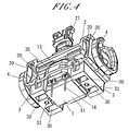
- Figs. 3 and 4 show a vibratory linear actuator in accordance with another embodiment of the present invention.
- This actuator has essentially the same configuration as that of the actuator of the preceding embodiment.
- the actuator further includes bridges 35 integrally formed with the support units 3 for interconnecting the support units 3 spaced apart in the vibration direction of the movable members 2. Presence of the bridges 35 increases the resistance of the support units 3 against the torsional forces applied thereto. This makes it possible for the actuator to enjoy enhanced characteristics.
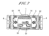
- Figs. 5 through 8 show a vibratory linear actuator in accordance with a further embodiment of the present invention.
- a cover 5 for arranging the power-supplying lead lines (not shown) leading to a pair of coil terminals 14 to which the windings 13 of the stator 1 are connected is attached to the stator 1 and the lower surfaces of the support units 3.
- the cover 5 is made of a synthetic resin and is provided with a plurality of hooks 50 at its outer periphery. The hooks 50 are locked into engagement recesses 36 so that the cover 5 can cover the lower surfaces of the stator 1 and the support units 3.
- the cover 5 includes wiring arrangement portions 51 for hooking and arranging the lead lines on its lower surface and through-holes 52 through which the screws 60 for fixing the actuator to the housing 6 is inserted.
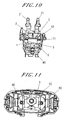
- Figs. 9 through 11 show the vibratory linear actuator provided with the cover 5.
- Fig. 12 shows a vibratory linear actuator in accordance with a still further embodiment of the present invention. This actuator is not provided with the cover 5 and is fixed to the housing 6 by means of the screws 60.
- the vibratory linear actuator may be fixed to the housing 6 by a fixing means other than the screws 60.
- a fixing means other than the screws 60.
- fastener hooks 61 are formed on the inner surface of the housing 6 and are locked against the upper edge of the support units 3 fitted into the housing 6, thereby fixing the support units 3 and the stator 1, namely the vibratory linear actuator, to the housing 6.
- the housing 6 is configured to surround the vibratory linear actuator and is coupled to the main body (not shown) of an electric razor serving as a grip portion.
- a blade frame for holding an external razor blade is connected to the upper surface of the housing 6.
- a hole 63 through which to pass the lead lines is formed on the lower surface of the housing 6.
- the assembling process of the vibratory linear actuator is finalized by assembling the same on the housing 6, it is impossible to perform accurate examination of the characteristics unless the actuator is fixed to the housing 6.
- the height of at least a portion of the housing 6 is set so as to make the gap between the stator 1 and the permanent magnets 22 visible from the outside as indicated by a chain line L in Fig. 8 , it becomes possible to see the gap size with naked eyes, which makes it easy to perform examination or other tasks.
- the electromagnet is arranged in the stator 1 and the permanent magnets 22 are arranged in the movable members 2 in the foregoing embodiments
- the present invention can apply to a case where a permanent magnet is arranged in the stator 1 and electromagnets are arranged in the movable members 2.
- protrusion portions 15 as engagement portions are formed in the back yoke 23 arranged at the rear of the permanent magnet of the stator 1.
- stator 1 is connected and fixed to the support units 3 in the foregoing embodiments, the stator 1 and the support units 3 may be connected to each other by resilient pieces 38 and driven in the left-and-right direction as shown in Fig. 15 .
- the stator 1 and the movable member(s) 2 may be allowed to vibrate in opposite phases.
Landscapes
- Engineering & Computer Science (AREA)
- Power Engineering (AREA)
- Reciprocating, Oscillating Or Vibrating Motors (AREA)
Applications Claiming Priority (1)
| Application Number | Priority Date | Filing Date | Title |
|---|---|---|---|
| JP2008114614A JP4497227B2 (ja) | 2008-04-24 | 2008-04-24 | 振動型リニアアクチュエータ |
Publications (3)
| Publication Number | Publication Date |
|---|---|
| EP2112754A2 true EP2112754A2 (de) | 2009-10-28 |
| EP2112754A3 EP2112754A3 (de) | 2017-03-08 |
| EP2112754B1 EP2112754B1 (de) | 2021-06-09 |
Family
ID=40910964
Family Applications (1)
| Application Number | Title | Priority Date | Filing Date |
|---|---|---|---|
| EP09005370.3A Active EP2112754B1 (de) | 2008-04-24 | 2009-04-15 | Vibrierender Linearaktuator |
Country Status (5)
| Country | Link |
|---|---|
| US (1) | US7965000B2 (de) |
| EP (1) | EP2112754B1 (de) |
| JP (1) | JP4497227B2 (de) |
| CN (1) | CN101599684B (de) |
| RU (1) | RU2395152C1 (de) |
Cited By (2)
| Publication number | Priority date | Publication date | Assignee | Title |
|---|---|---|---|---|
| EP2790309A4 (de) * | 2011-12-05 | 2015-12-30 | Panasonic Corp | Linearantrieb und mundhygienevorrichtung |
| EP2940843A4 (de) * | 2012-12-27 | 2016-04-27 | Panasonic Ip Man Co Ltd | Elektrischer schubantrieb und elektrische ausgangswellenvibrationsvorrichtung mit besagtem elektrischen linearantrieb |
Families Citing this family (12)
| Publication number | Priority date | Publication date | Assignee | Title |
|---|---|---|---|---|
| JP5624417B2 (ja) * | 2010-09-27 | 2014-11-12 | パナソニック株式会社 | 振動型リニアアクチュエータ |
| CN102545526B (zh) * | 2010-12-20 | 2016-01-06 | 德昌电机(深圳)有限公司 | 致动器 |
| US9590463B2 (en) | 2011-09-22 | 2017-03-07 | Minebea Co., Ltd. | Vibration generator moving vibrator by magnetic field generated by coil and holder used in vibration-generator |
| JP6793366B2 (ja) * | 2017-04-19 | 2020-12-02 | パナソニックIpマネジメント株式会社 | 振動型リニアアクチュエータ、および、切断装置 |
| JP6765079B2 (ja) * | 2017-04-19 | 2020-10-07 | パナソニックIpマネジメント株式会社 | 振動型リニアアクチュエータ、および、体毛処理機 |
| JP6715465B2 (ja) | 2017-04-19 | 2020-07-01 | パナソニックIpマネジメント株式会社 | 振動型リニアアクチュエータ、体毛処理機及び振動型リニアアクチュエータの製造方法 |
| JP6854695B2 (ja) * | 2017-05-02 | 2021-04-07 | マクセルイズミ株式会社 | 往復式電気かみそり |
| CN108258874B (zh) * | 2017-12-27 | 2019-11-01 | 广州赤力科技有限公司 | 摆动马达及电动装置 |
| CN108400690A (zh) * | 2018-05-18 | 2018-08-14 | 东莞市沃伦电子科技有限公司 | 电磁动力驱动机构及具有所述驱动机构的护理装置 |
| WO2021252731A1 (en) | 2020-06-11 | 2021-12-16 | Andis Company | Hair clipper with linear actuator |
| CN113894847B (zh) * | 2021-11-09 | 2024-11-22 | 浙江海顺电工有限公司 | 一种减振摆动机构及剃须刀 |
| CN219918596U (zh) * | 2023-02-28 | 2023-10-27 | 惠州市德信和实业有限公司 | 磁力传动机构及震动装置 |
Citations (1)
| Publication number | Priority date | Publication date | Assignee | Title |
|---|---|---|---|---|
| JP2005354879A (ja) | 2004-06-14 | 2005-12-22 | Matsushita Electric Works Ltd | 振動型リニアアクチュエータ及びこれを用いた往復式電気かみそり |
Family Cites Families (16)
| Publication number | Priority date | Publication date | Assignee | Title |
|---|---|---|---|---|
| WO1995026261A1 (en) * | 1994-03-28 | 1995-10-05 | Matsushita Electric Works, Ltd. | Reciprocatory dry shaver |
| JP3382058B2 (ja) | 1995-05-26 | 2003-03-04 | 松下電工株式会社 | リニアアクチュエータ |
| JP3266757B2 (ja) * | 1995-05-26 | 2002-03-18 | 松下電工株式会社 | 振動型リニアアクチュエータ |
| DE19736776C2 (de) * | 1997-08-23 | 1999-06-02 | Braun Gmbh | Trockenrasierapparat |
| EP1162721B1 (de) * | 2000-06-07 | 2005-12-21 | Matsushita Electric Works, Ltd. | Lineare Schwingungsvorrichtung |
| JP3707421B2 (ja) * | 2001-10-26 | 2005-10-19 | 松下電工株式会社 | 振動型リニアアクチュエータ |
| JP2004023908A (ja) * | 2002-06-17 | 2004-01-22 | Matsushita Electric Works Ltd | 振動型リニアアクチュエータ |
| JP3915607B2 (ja) * | 2002-06-17 | 2007-05-16 | 松下電工株式会社 | 振動型リニアアクチュエータとこれを用いた電気かみそり |
| JP3928495B2 (ja) * | 2002-06-17 | 2007-06-13 | 松下電工株式会社 | 振動型リニアアクチュエータ |
| JP2005185067A (ja) * | 2003-12-22 | 2005-07-07 | Matsushita Electric Works Ltd | 振動型リニアアクチュエータ及びこれを備えたヘアカッター |
| JP2004154000A (ja) * | 2004-01-23 | 2004-05-27 | Toshiba Corp | 回転電機 |
| JP4576919B2 (ja) * | 2004-07-30 | 2010-11-10 | パナソニック電工株式会社 | 往復式電気かみそり |
| JP4392608B2 (ja) * | 2004-11-11 | 2010-01-06 | 東海ゴム工業株式会社 | 能動型防振装置 |
| JP4400742B2 (ja) * | 2004-11-11 | 2010-01-20 | 東海ゴム工業株式会社 | 能動型防振装置 |
| JP2006300308A (ja) * | 2005-03-22 | 2006-11-02 | Toyo Tire & Rubber Co Ltd | 防振装置 |
| JP4631846B2 (ja) | 2006-12-18 | 2011-02-16 | パナソニック電工株式会社 | 振動型リニアアクチュエータ |
-
2008
- 2008-04-24 JP JP2008114614A patent/JP4497227B2/ja active Active
-
2009
- 2009-04-15 EP EP09005370.3A patent/EP2112754B1/de active Active
- 2009-04-20 US US12/385,769 patent/US7965000B2/en active Active
- 2009-04-23 RU RU2009115501/09A patent/RU2395152C1/ru active
- 2009-04-24 CN CN2009101369046A patent/CN101599684B/zh active Active
Patent Citations (1)
| Publication number | Priority date | Publication date | Assignee | Title |
|---|---|---|---|---|
| JP2005354879A (ja) | 2004-06-14 | 2005-12-22 | Matsushita Electric Works Ltd | 振動型リニアアクチュエータ及びこれを用いた往復式電気かみそり |
Cited By (2)
| Publication number | Priority date | Publication date | Assignee | Title |
|---|---|---|---|---|
| EP2790309A4 (de) * | 2011-12-05 | 2015-12-30 | Panasonic Corp | Linearantrieb und mundhygienevorrichtung |
| EP2940843A4 (de) * | 2012-12-27 | 2016-04-27 | Panasonic Ip Man Co Ltd | Elektrischer schubantrieb und elektrische ausgangswellenvibrationsvorrichtung mit besagtem elektrischen linearantrieb |
Also Published As
| Publication number | Publication date |
|---|---|
| US20090267422A1 (en) | 2009-10-29 |
| US7965000B2 (en) | 2011-06-21 |
| RU2395152C1 (ru) | 2010-07-20 |
| JP4497227B2 (ja) | 2010-07-07 |
| CN101599684B (zh) | 2012-07-25 |
| JP2009268251A (ja) | 2009-11-12 |
| EP2112754B1 (de) | 2021-06-09 |
| CN101599684A (zh) | 2009-12-09 |
| EP2112754A3 (de) | 2017-03-08 |
Similar Documents
| Publication | Publication Date | Title |
|---|---|---|
| EP2112754B1 (de) | Vibrierender Linearaktuator | |
| EP3442103B1 (de) | Linearer oszillierender Aktuator | |
| US20200412228A1 (en) | Vibration motor | |
| US20200044538A1 (en) | Linear vibration motor | |
| EP2790309A1 (de) | Linearantrieb und mundhygienevorrichtung | |
| JP6803722B2 (ja) | リニア振動モータ | |
| JP2005185067A (ja) | 振動型リニアアクチュエータ及びこれを備えたヘアカッター | |
| JP4487650B2 (ja) | 振動型リニアアクチュエータ及びこれを用いた往復式電気かみそり | |
| CN210167934U (zh) | 振动电机 | |
| KR101497216B1 (ko) | 리니어 모터 | |
| CN119051391A (zh) | 振动型线性致动器、振动型线性致动器的相对于被固定部的固定构造以及切断装置 | |
| JP5260927B2 (ja) | 振動型リニアアクチュエータ | |
| JP2004016524A (ja) | 振動型リニアアクチュエータ及びこれを用いた電気かみそり | |
| KR100543098B1 (ko) | 진동형 리니어 액츄에이터 | |
| JP2007104898A (ja) | 振動型リニアアクチュエータ | |
| KR101027215B1 (ko) | 진동형 리니어 액추에이터 | |
| CN109617355B (zh) | 线性振动电机 | |
| JPH11285226A (ja) | 振動型リニアアクチュエータ | |
| HK1138949A (en) | Vibratory linear actuator | |
| JP5123040B2 (ja) | 振動型リニアアクチュエータ | |
| JP4631846B2 (ja) | 振動型リニアアクチュエータ | |
| EP3776824A1 (de) | Motor für eine körperpflegevorrichtung | |
| JP3736296B2 (ja) | 振動型リニアアクチュエータ | |
| CN119051392A (zh) | 振动型线性致动器以及切断装置 | |
| JP3382057B2 (ja) | リニアアクチュエータ |
Legal Events
| Date | Code | Title | Description |
|---|---|---|---|
| PUAI | Public reference made under article 153(3) epc to a published international application that has entered the european phase |
Free format text: ORIGINAL CODE: 0009012 |
|
| AK | Designated contracting states |
Kind code of ref document: A2 Designated state(s): AT BE BG CH CY CZ DE DK EE ES FI FR GB GR HR HU IE IS IT LI LT LU LV MC MK MT NL NO PL PT RO SE SI SK TR |
|
| RAP1 | Party data changed (applicant data changed or rights of an application transferred) |
Owner name: PANASONIC CORPORATION |
|
| REG | Reference to a national code |
Ref country code: DE Ref legal event code: R079 Ref document number: 602009063775 Country of ref document: DE Free format text: PREVIOUS MAIN CLASS: H02K0033020000 Ipc: H02K0033160000 |
|
| PUAL | Search report despatched |
Free format text: ORIGINAL CODE: 0009013 |
|
| AK | Designated contracting states |
Kind code of ref document: A3 Designated state(s): AT BE BG CH CY CZ DE DK EE ES FI FR GB GR HR HU IE IS IT LI LT LU LV MC MK MT NL NO PL PT RO SE SI SK TR |
|
| AX | Request for extension of the european patent |
Extension state: AL BA RS |
|
| RIC1 | Information provided on ipc code assigned before grant |
Ipc: H02K 5/04 20060101ALI20170127BHEP Ipc: H02K 33/16 20060101AFI20170127BHEP |
|
| STAA | Information on the status of an ep patent application or granted ep patent |
Free format text: STATUS: REQUEST FOR EXAMINATION WAS MADE |
|
| 17P | Request for examination filed |
Effective date: 20170907 |
|
| RBV | Designated contracting states (corrected) |
Designated state(s): AT BE BG CH CY CZ DE DK EE ES FI FR GB GR HR HU IE IS IT LI LT LU LV MC MK MT NL NO PL PT RO SE SI SK TR |
|
| STAA | Information on the status of an ep patent application or granted ep patent |
Free format text: STATUS: EXAMINATION IS IN PROGRESS |
|
| 17Q | First examination report despatched |
Effective date: 20180316 |
|
| GRAP | Despatch of communication of intention to grant a patent |
Free format text: ORIGINAL CODE: EPIDOSNIGR1 |
|
| STAA | Information on the status of an ep patent application or granted ep patent |
Free format text: STATUS: GRANT OF PATENT IS INTENDED |
|
| INTG | Intention to grant announced |
Effective date: 20201208 |
|
| RIN1 | Information on inventor provided before grant (corrected) |
Inventor name: MORIGUCHI, MASASHI Inventor name: KOMORI, SHUNSUKE |
|
| GRAS | Grant fee paid |
Free format text: ORIGINAL CODE: EPIDOSNIGR3 |
|
| GRAA | (expected) grant |
Free format text: ORIGINAL CODE: 0009210 |
|
| STAA | Information on the status of an ep patent application or granted ep patent |
Free format text: STATUS: THE PATENT HAS BEEN GRANTED |
|
| AK | Designated contracting states |
Kind code of ref document: B1 Designated state(s): AT BE BG CH CY CZ DE DK EE ES FI FR GB GR HR HU IE IS IT LI LT LU LV MC MK MT NL NO PL PT RO SE SI SK TR |
|
| REG | Reference to a national code |
Ref country code: GB Ref legal event code: FG4D |
|
| REG | Reference to a national code |
Ref country code: CH Ref legal event code: EP Ref country code: AT Ref legal event code: REF Ref document number: 1401292 Country of ref document: AT Kind code of ref document: T Effective date: 20210615 |
|
| REG | Reference to a national code |
Ref country code: DE Ref legal event code: R096 Ref document number: 602009063775 Country of ref document: DE |
|
| REG | Reference to a national code |
Ref country code: IE Ref legal event code: FG4D |
|
| REG | Reference to a national code |
Ref country code: LT Ref legal event code: MG9D |
|
| PG25 | Lapsed in a contracting state [announced via postgrant information from national office to epo] |
Ref country code: BG Free format text: LAPSE BECAUSE OF FAILURE TO SUBMIT A TRANSLATION OF THE DESCRIPTION OR TO PAY THE FEE WITHIN THE PRESCRIBED TIME-LIMIT Effective date: 20210909 Ref country code: HR Free format text: LAPSE BECAUSE OF FAILURE TO SUBMIT A TRANSLATION OF THE DESCRIPTION OR TO PAY THE FEE WITHIN THE PRESCRIBED TIME-LIMIT Effective date: 20210609 Ref country code: FI Free format text: LAPSE BECAUSE OF FAILURE TO SUBMIT A TRANSLATION OF THE DESCRIPTION OR TO PAY THE FEE WITHIN THE PRESCRIBED TIME-LIMIT Effective date: 20210609 Ref country code: LT Free format text: LAPSE BECAUSE OF FAILURE TO SUBMIT A TRANSLATION OF THE DESCRIPTION OR TO PAY THE FEE WITHIN THE PRESCRIBED TIME-LIMIT Effective date: 20210609 |
|
| REG | Reference to a national code |
Ref country code: AT Ref legal event code: MK05 Ref document number: 1401292 Country of ref document: AT Kind code of ref document: T Effective date: 20210609 |
|
| REG | Reference to a national code |
Ref country code: NL Ref legal event code: MP Effective date: 20210609 |
|
| PG25 | Lapsed in a contracting state [announced via postgrant information from national office to epo] |
Ref country code: LV Free format text: LAPSE BECAUSE OF FAILURE TO SUBMIT A TRANSLATION OF THE DESCRIPTION OR TO PAY THE FEE WITHIN THE PRESCRIBED TIME-LIMIT Effective date: 20210609 Ref country code: GR Free format text: LAPSE BECAUSE OF FAILURE TO SUBMIT A TRANSLATION OF THE DESCRIPTION OR TO PAY THE FEE WITHIN THE PRESCRIBED TIME-LIMIT Effective date: 20210910 Ref country code: SE Free format text: LAPSE BECAUSE OF FAILURE TO SUBMIT A TRANSLATION OF THE DESCRIPTION OR TO PAY THE FEE WITHIN THE PRESCRIBED TIME-LIMIT Effective date: 20210609 Ref country code: NO Free format text: LAPSE BECAUSE OF FAILURE TO SUBMIT A TRANSLATION OF THE DESCRIPTION OR TO PAY THE FEE WITHIN THE PRESCRIBED TIME-LIMIT Effective date: 20210909 |
|
| PG25 | Lapsed in a contracting state [announced via postgrant information from national office to epo] |
Ref country code: EE Free format text: LAPSE BECAUSE OF FAILURE TO SUBMIT A TRANSLATION OF THE DESCRIPTION OR TO PAY THE FEE WITHIN THE PRESCRIBED TIME-LIMIT Effective date: 20210609 Ref country code: CZ Free format text: LAPSE BECAUSE OF FAILURE TO SUBMIT A TRANSLATION OF THE DESCRIPTION OR TO PAY THE FEE WITHIN THE PRESCRIBED TIME-LIMIT Effective date: 20210609 Ref country code: SK Free format text: LAPSE BECAUSE OF FAILURE TO SUBMIT A TRANSLATION OF THE DESCRIPTION OR TO PAY THE FEE WITHIN THE PRESCRIBED TIME-LIMIT Effective date: 20210609 Ref country code: AT Free format text: LAPSE BECAUSE OF FAILURE TO SUBMIT A TRANSLATION OF THE DESCRIPTION OR TO PAY THE FEE WITHIN THE PRESCRIBED TIME-LIMIT Effective date: 20210609 Ref country code: NL Free format text: LAPSE BECAUSE OF FAILURE TO SUBMIT A TRANSLATION OF THE DESCRIPTION OR TO PAY THE FEE WITHIN THE PRESCRIBED TIME-LIMIT Effective date: 20210609 Ref country code: PT Free format text: LAPSE BECAUSE OF FAILURE TO SUBMIT A TRANSLATION OF THE DESCRIPTION OR TO PAY THE FEE WITHIN THE PRESCRIBED TIME-LIMIT Effective date: 20211011 Ref country code: RO Free format text: LAPSE BECAUSE OF FAILURE TO SUBMIT A TRANSLATION OF THE DESCRIPTION OR TO PAY THE FEE WITHIN THE PRESCRIBED TIME-LIMIT Effective date: 20210609 Ref country code: ES Free format text: LAPSE BECAUSE OF FAILURE TO SUBMIT A TRANSLATION OF THE DESCRIPTION OR TO PAY THE FEE WITHIN THE PRESCRIBED TIME-LIMIT Effective date: 20210609 |
|
| PG25 | Lapsed in a contracting state [announced via postgrant information from national office to epo] |
Ref country code: PL Free format text: LAPSE BECAUSE OF FAILURE TO SUBMIT A TRANSLATION OF THE DESCRIPTION OR TO PAY THE FEE WITHIN THE PRESCRIBED TIME-LIMIT Effective date: 20210609 |
|
| REG | Reference to a national code |
Ref country code: DE Ref legal event code: R097 Ref document number: 602009063775 Country of ref document: DE |
|
| PLBE | No opposition filed within time limit |
Free format text: ORIGINAL CODE: 0009261 |
|
| STAA | Information on the status of an ep patent application or granted ep patent |
Free format text: STATUS: NO OPPOSITION FILED WITHIN TIME LIMIT |
|
| PG25 | Lapsed in a contracting state [announced via postgrant information from national office to epo] |
Ref country code: DK Free format text: LAPSE BECAUSE OF FAILURE TO SUBMIT A TRANSLATION OF THE DESCRIPTION OR TO PAY THE FEE WITHIN THE PRESCRIBED TIME-LIMIT Effective date: 20210609 |
|
| 26N | No opposition filed |
Effective date: 20220310 |
|
| PG25 | Lapsed in a contracting state [announced via postgrant information from national office to epo] |
Ref country code: IT Free format text: LAPSE BECAUSE OF FAILURE TO SUBMIT A TRANSLATION OF THE DESCRIPTION OR TO PAY THE FEE WITHIN THE PRESCRIBED TIME-LIMIT Effective date: 20210609 |
|
| REG | Reference to a national code |
Ref country code: CH Ref legal event code: PL |
|
| GBPC | Gb: european patent ceased through non-payment of renewal fee |
Effective date: 20220415 |
|
| REG | Reference to a national code |
Ref country code: BE Ref legal event code: MM Effective date: 20220430 |
|
| PG25 | Lapsed in a contracting state [announced via postgrant information from national office to epo] |
Ref country code: MC Free format text: LAPSE BECAUSE OF FAILURE TO SUBMIT A TRANSLATION OF THE DESCRIPTION OR TO PAY THE FEE WITHIN THE PRESCRIBED TIME-LIMIT Effective date: 20210609 Ref country code: LU Free format text: LAPSE BECAUSE OF NON-PAYMENT OF DUE FEES Effective date: 20220415 Ref country code: LI Free format text: LAPSE BECAUSE OF NON-PAYMENT OF DUE FEES Effective date: 20220430 Ref country code: GB Free format text: LAPSE BECAUSE OF NON-PAYMENT OF DUE FEES Effective date: 20220415 Ref country code: FR Free format text: LAPSE BECAUSE OF NON-PAYMENT OF DUE FEES Effective date: 20220430 Ref country code: CH Free format text: LAPSE BECAUSE OF NON-PAYMENT OF DUE FEES Effective date: 20220430 |
|
| PG25 | Lapsed in a contracting state [announced via postgrant information from national office to epo] |
Ref country code: BE Free format text: LAPSE BECAUSE OF NON-PAYMENT OF DUE FEES Effective date: 20220430 |
|
| PG25 | Lapsed in a contracting state [announced via postgrant information from national office to epo] |
Ref country code: IE Free format text: LAPSE BECAUSE OF NON-PAYMENT OF DUE FEES Effective date: 20220415 |
|
| PG25 | Lapsed in a contracting state [announced via postgrant information from national office to epo] |
Ref country code: HU Free format text: LAPSE BECAUSE OF FAILURE TO SUBMIT A TRANSLATION OF THE DESCRIPTION OR TO PAY THE FEE WITHIN THE PRESCRIBED TIME-LIMIT; INVALID AB INITIO Effective date: 20090415 |
|
| PG25 | Lapsed in a contracting state [announced via postgrant information from national office to epo] |
Ref country code: MK Free format text: LAPSE BECAUSE OF FAILURE TO SUBMIT A TRANSLATION OF THE DESCRIPTION OR TO PAY THE FEE WITHIN THE PRESCRIBED TIME-LIMIT Effective date: 20210609 Ref country code: CY Free format text: LAPSE BECAUSE OF FAILURE TO SUBMIT A TRANSLATION OF THE DESCRIPTION OR TO PAY THE FEE WITHIN THE PRESCRIBED TIME-LIMIT Effective date: 20210609 |
|
| PG25 | Lapsed in a contracting state [announced via postgrant information from national office to epo] |
Ref country code: TR Free format text: LAPSE BECAUSE OF FAILURE TO SUBMIT A TRANSLATION OF THE DESCRIPTION OR TO PAY THE FEE WITHIN THE PRESCRIBED TIME-LIMIT Effective date: 20210609 |
|
| PG25 | Lapsed in a contracting state [announced via postgrant information from national office to epo] |
Ref country code: MT Free format text: LAPSE BECAUSE OF FAILURE TO SUBMIT A TRANSLATION OF THE DESCRIPTION OR TO PAY THE FEE WITHIN THE PRESCRIBED TIME-LIMIT Effective date: 20210609 |
|
| PGFP | Annual fee paid to national office [announced via postgrant information from national office to epo] |
Ref country code: DE Payment date: 20250422 Year of fee payment: 17 |