EP2113184B1 - Presse à comprimés rotative - Google Patents
Presse à comprimés rotative Download PDFInfo
- Publication number
- EP2113184B1 EP2113184B1 EP20090157708 EP09157708A EP2113184B1 EP 2113184 B1 EP2113184 B1 EP 2113184B1 EP 20090157708 EP20090157708 EP 20090157708 EP 09157708 A EP09157708 A EP 09157708A EP 2113184 B1 EP2113184 B1 EP 2113184B1
- Authority
- EP
- European Patent Office
- Prior art keywords
- secondary air
- suction
- vacuum cleaning
- air opening
- opening
- Prior art date
- Legal status (The legal status is an assumption and is not a legal conclusion. Google has not performed a legal analysis and makes no representation as to the accuracy of the status listed.)
- Active
Links
Images




Classifications
-
- A—HUMAN NECESSITIES
- A47—FURNITURE; DOMESTIC ARTICLES OR APPLIANCES; COFFEE MILLS; SPICE MILLS; SUCTION CLEANERS IN GENERAL
- A47L—DOMESTIC WASHING OR CLEANING; SUCTION CLEANERS IN GENERAL
- A47L9/00—Details or accessories of suction cleaners, e.g. mechanical means for controlling the suction or for effecting pulsating action; Storing devices specially adapted to suction cleaners or parts thereof; Carrying-vehicles specially adapted for suction cleaners
- A47L9/02—Nozzles
-
- A—HUMAN NECESSITIES
- A47—FURNITURE; DOMESTIC ARTICLES OR APPLIANCES; COFFEE MILLS; SPICE MILLS; SUCTION CLEANERS IN GENERAL
- A47L—DOMESTIC WASHING OR CLEANING; SUCTION CLEANERS IN GENERAL
- A47L9/00—Details or accessories of suction cleaners, e.g. mechanical means for controlling the suction or for effecting pulsating action; Storing devices specially adapted to suction cleaners or parts thereof; Carrying-vehicles specially adapted for suction cleaners
- A47L9/0072—Mechanical means for controlling the suction or for effecting pulsating action
-
- A—HUMAN NECESSITIES
- A47—FURNITURE; DOMESTIC ARTICLES OR APPLIANCES; COFFEE MILLS; SPICE MILLS; SUCTION CLEANERS IN GENERAL
- A47L—DOMESTIC WASHING OR CLEANING; SUCTION CLEANERS IN GENERAL
- A47L9/00—Details or accessories of suction cleaners, e.g. mechanical means for controlling the suction or for effecting pulsating action; Storing devices specially adapted to suction cleaners or parts thereof; Carrying-vehicles specially adapted for suction cleaners
- A47L9/24—Hoses or pipes; Hose or pipe couplings
- A47L9/248—Parts, details or accessories of hoses or pipes
-
- A—HUMAN NECESSITIES
- A47—FURNITURE; DOMESTIC ARTICLES OR APPLIANCES; COFFEE MILLS; SPICE MILLS; SUCTION CLEANERS IN GENERAL
- A47L—DOMESTIC WASHING OR CLEANING; SUCTION CLEANERS IN GENERAL
- A47L9/00—Details or accessories of suction cleaners, e.g. mechanical means for controlling the suction or for effecting pulsating action; Storing devices specially adapted to suction cleaners or parts thereof; Carrying-vehicles specially adapted for suction cleaners
- A47L9/28—Installation of the electric equipment, e.g. adaptation or attachment to the suction cleaner; Controlling suction cleaners by electric means
- A47L9/2805—Parameters or conditions being sensed
- A47L9/281—Parameters or conditions being sensed the amount or condition of incoming dirt or dust
-
- A—HUMAN NECESSITIES
- A47—FURNITURE; DOMESTIC ARTICLES OR APPLIANCES; COFFEE MILLS; SPICE MILLS; SUCTION CLEANERS IN GENERAL
- A47L—DOMESTIC WASHING OR CLEANING; SUCTION CLEANERS IN GENERAL
- A47L9/00—Details or accessories of suction cleaners, e.g. mechanical means for controlling the suction or for effecting pulsating action; Storing devices specially adapted to suction cleaners or parts thereof; Carrying-vehicles specially adapted for suction cleaners
- A47L9/28—Installation of the electric equipment, e.g. adaptation or attachment to the suction cleaner; Controlling suction cleaners by electric means
- A47L9/2836—Installation of the electric equipment, e.g. adaptation or attachment to the suction cleaner; Controlling suction cleaners by electric means characterised by the parts which are controlled
-
- A—HUMAN NECESSITIES
- A47—FURNITURE; DOMESTIC ARTICLES OR APPLIANCES; COFFEE MILLS; SPICE MILLS; SUCTION CLEANERS IN GENERAL
- A47L—DOMESTIC WASHING OR CLEANING; SUCTION CLEANERS IN GENERAL
- A47L9/00—Details or accessories of suction cleaners, e.g. mechanical means for controlling the suction or for effecting pulsating action; Storing devices specially adapted to suction cleaners or parts thereof; Carrying-vehicles specially adapted for suction cleaners
- A47L9/28—Installation of the electric equipment, e.g. adaptation or attachment to the suction cleaner; Controlling suction cleaners by electric means
- A47L9/2836—Installation of the electric equipment, e.g. adaptation or attachment to the suction cleaner; Controlling suction cleaners by electric means characterised by the parts which are controlled
- A47L9/2842—Suction motors or blowers
-
- A—HUMAN NECESSITIES
- A47—FURNITURE; DOMESTIC ARTICLES OR APPLIANCES; COFFEE MILLS; SPICE MILLS; SUCTION CLEANERS IN GENERAL
- A47L—DOMESTIC WASHING OR CLEANING; SUCTION CLEANERS IN GENERAL
- A47L9/00—Details or accessories of suction cleaners, e.g. mechanical means for controlling the suction or for effecting pulsating action; Storing devices specially adapted to suction cleaners or parts thereof; Carrying-vehicles specially adapted for suction cleaners
- A47L9/28—Installation of the electric equipment, e.g. adaptation or attachment to the suction cleaner; Controlling suction cleaners by electric means
- A47L9/2889—Safety or protection devices or systems, e.g. for prevention of motor over-heating or for protection of the user
-
- E—FIXED CONSTRUCTIONS
- E05—LOCKS; KEYS; WINDOW OR DOOR FITTINGS; SAFES
- E05C—BOLTS OR FASTENING DEVICES FOR WINGS, SPECIALLY FOR DOORS OR WINDOWS
- E05C19/00—Other devices specially designed for securing wings, e.g. with suction cups
- E05C19/16—Devices holding the wing by magnetic or electromagnetic attraction
- E05C19/166—Devices holding the wing by magnetic or electromagnetic attraction electromagnetic
-
- E—FIXED CONSTRUCTIONS
- E05—LOCKS; KEYS; WINDOW OR DOOR FITTINGS; SAFES
- E05B—LOCKS; ACCESSORIES THEREFOR; HANDCUFFS
- E05B65/00—Locks or fastenings for special use
- E05B65/006—Locks or fastenings for special use for covers or panels
Definitions
- the invention relates to an electromotive operated Saugquess réelle with a suction port and a suction channel, wherein in addition a humidity sensor is arranged in the suction channel.
- Vacuum cleaning devices of the type in question are known, in particular as household vacuum cleaners, further than especially hand-held vacuum cleaners, but also in the form of autonomously operating, electric motor driven floor cleaning equipment such as suction and / or sweeping robot.
- a moisture sensor arranged in the suction channel detects liquid absorbed via the suction mouth of the vacuum cleaning device.
- a correspondingly generated signal upon exposure to moisture leads in the known state of the art to a shutdown of the suction air flow delivering the blower motor.
- the electric motor-driven blower runs after a shutdown of the same, continues to generate a corresponding, albeit continuously decreasing suction air flow, so that absorbed and detected via the humidity sensor moisture is further absorbed in the course of the blower outlet in the device. This can lead to malfunctioning up to destruction of the filter bag collecting the absorbent material or, moreover, of the fan motor.
- the DE 8915 511 U1 discloses an electric motor operated Saugquess réelle with a suction mouth and a suction channel, wherein a humidity sensor is arranged in the suction channel. Detecting fluid leads to the blower motor of the suction device being switched off.
- a comparable embodiment is also from the JP 4028327 A known.
- the invention provides the task to implement the detection of moisture for the Saugquessêt low.
- This object is achieved in the subject matter of claim 1, wherein it is geared to that of the suction channel at Erfas-sung a humidity in the sense of a secondary air opening opens.
- This secondary air opening is spatially spaced from the suction mouth facing the floor to be cleaned, via which the suction material and optionally moisture is absorbed.
- this secondary air opening is preferably provided in the flow direction behind the suction mouth, further between the suction mouth and to be protected suction fan or filter bag.
- the suction air stream at the suction mouth and thus at the location of the moisture to be absorbed ruptures, so that fan after-run due to switching-off of the electric motor initiated by moisture detection causes suction via the secondary air opening spaced from the moisture region. Accordingly, humid-free secondary air is sucked in via the flow caused by the fan running out. Downstream components such as a filter bag or the blower motor are protected according to this embodiment from absorbed moisture.
- the negative pressure in the humidity range is interrupted.
- the opening of the secondary air opening is controlled by a moisture sensor signal generated when moisture is applied.
- the secondary air opening is spatially associated with the humidity sensor.
- a flap closing the secondary air opening in the normal state of use of the cleaning device is positioned laterally and / or above the humidity sensor.
- the secondary air opening has an opening cross-section which is at least equal to, more preferably greater than the Saugmundquerites.
- the secondary air opening or a cover closing the secondary air opening in the usual suction mode or an occlusive flap moves a checking and / or cleaning agent in contact with the humidity sensor.
- This checking and / or cleaning agent is used in a preferred embodiment, a self-test of the device before restarting after a Moisture detection, more preferably also every time the device to check the function. This ensures that the humidity sensors are active and react accordingly in suction mode when moisture is applied.
- the moisture sensor is removed from any adhering dirt, such as moist dust particles or the like, via the cleaning agent coming into contact with the humidity sensor in order to ensure the proper condition of the humidity sensor when the device is restarted.
- the vacuum cleaning device is preferably reusable after a moisture detection.
- the secondary air opening is achieved by opening a part of the Saugkanalwandung.
- the guided through the device suction channel is usually like a tube, with a circular or even deviating cross-sectional shape.
- the flow channel can also have a rectangular design in cross-section, wherein the part which opens and opens the secondary air opening is further formed in this case by a ceiling section of the suction channel.
- the secondary air opening sealingly closing part of the Saugkanalwandung is supported in the closed position.
- This holder is released upon detection of moisture through the humidity sensor and is in a further preferred embodiment only after a check by means of the checking means activated again.
- the closed position of the secondary air opening is secured by a magnet, more preferably by an electromagnet, which is energized only after a review of the humidity sensor and passed self-test of the device, for holding the side air opening closing wall part.
- the excitation of the magnet is interrupted, after which the secondary air opening is released.
- the open position of the secondary air opening is spring-assisted. The spring force is released automatically after the closure position has been canceled. Accordingly, provided springs are clamped in the secondary air opening-closing position.
- the moisture sensor is formed in a further preferred embodiment as a capacitive humidity sensor, further consists of two spaced apart sensor parts. These sensor parts form two poles to open the capacitive field between the sensor surfaces.
- the sensor parts are preferably not facing the flow channel isolated. Alternatively, however, an insulation may be provided, but without an air gap between the insulation and the sensor part.
- the selected configuration of the humidity sensor a capacitor is formed with two plates. When dry, the dielectric is air. As soon as moisture is sucked through the suction channel, it is preferred forcibly guided over the humidity sensor, which results in a reduction of the dielectric.
- the checking means preferably consists of a short-circuiting means bridging the sensor parts, so on in the form of a wire, a metal bridge or, alternatively, in the form of an electrically conductive metal tuft or a metal brush. About this means the sensor parts are short-circuited in the self-test. The measured value recorded here must approach zero, since there is practically no dielectric between the poles. Thus, according to a unique detection of moisture allows. If the detected measured value does not approach zero in the event of a short circuit, then a further thorough inspection of the sensor parts is required. The vacuum cleaning device is initially not in operation.
- the short-circuiting means act in particular in the form of an electrically conductive brush or a metal tuft as a cleaning agent of the sensor parts. The sensor surfaces are cleaned during the opening movement of the duct wall part to expose the secondary air opening. Any dirt is scraped off.
- Saugquess réelle S consisting of a vacuum cleaner 1, in particular household vacuum cleaner, which is designed as a hand-held handle unit, and a header 10 in the form of a Hartêtdüse.
- a vacuum cleaner 1 in particular household vacuum cleaner, which is designed as a hand-held handle unit
- a header 10 in the form of a Hartêtdüse.
- the features of the attachment 10 described below are also conceivable for attachments with rotating brushes for carpet cleaning.
- the vacuum cleaner 1 initially has a base unit 2, with an electric motor, not shown, for a suction fan. At the base unit 2 a provided for receiving the sucked-up dust, air-impermeable filter cartridge 3 is docked. This includes a filter bag 4.
- the base unit 2 has a gooseneck-shaped extension, which extends over the region of the filter cartridge 3. In the area of the free end, this extension forms a plug-in receptacle for a handle 6 of the vacuum cleaner 1. In the region of the free end of the stem 6, an actuating handle 7 is provided.
- This has a thumb-actuatable setting unit 8 in the form of a slide switch, via which the power of the electric motor accommodated in the base unit 2 or the suction blower driven via the latter is adjustable.
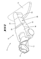
- the attachment 10 is composed essentially of a, on the floor to be cleaned 9 seated nozzle head 11 and a nozzle head 11 with the vacuum cleaner 1 connecting nozzle body 12, wherein on the nozzle body 12, a connecting piece 13 is formed for connecting the attachment 10 to the Vacuum cleaner 1.
- a suction channel 14 which opens into the nozzle head 11 extends.
- the there formed, the bottom 9 facing suction port carries the reference numeral 15th
- the suction channel 14 is surrounded by a nozzle housing 16, wherein further the suction channel 14 in the illustrated embodiment has a rectangular, approximately square cross-section with rounded corner regions.
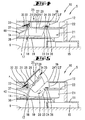
- a moisture sensor 17 is arranged downstream of the nozzle head 11 and the suction orifice 15 in the direction of flow r. This sits in the illustrated embodiment, the bottom side of the suction channel 14 and is formed as a capacitive humidity sensor of two transverse to the usual flow direction r spaced from each other arranged sensor parts 18. These, measuring poles forming sensor parts 18 are formed linsenkopfförmig and are electrically connected to an evaluation / tripping unit, not shown ,
- the sensor parts 18 are arranged in the region of a baffle-like water barrier 19 in order to supply drops, which are entrained via the air flow, to the sensor area in a targeted manner.
- an openable secondary air opening 20 is formed. This opens when needed to the environment, this further both sides across the longitudinal extent of the suction channel 14 as well as vertically above.
- the suction channel 14 is initially cut free in the region of both opposing Saugkanalwandungen 21 and in the region of the Saugkanaldecke 22. This results in lateral opening areas 23 and an upper opening area 24 merging into these. These lateral and upper opening areas 23 and 24 are again located in the adjacent sections of the nozzle housing 16. These areas are identified by reference numerals 23 'and 24'.
- This cover is achieved by a swing-open flap 25, the folding axis associated with the moisture sensor 17 facing the opening edge of the secondary air opening 20 is aligned transversely to the longitudinal extent of the suction channel 14.
- the flap 25 is initially part of the suction channel 14, this by forming the covering in the upper opening portion 24 ceiling portion 26 and the side thereto integrally formed, wing-like sowandungsabêten 27 which are assigned in the flap closing position the lateral opening portions 23 for sealing closure thereof.
- the flap 25 also carries a housing cover section 28 which is assigned to the upper opening region 24 'of the nozzle housing 16.
- Housing wall sections 29 for closing the lateral opening regions 23' are integrally formed laterally spaced from the flap-side side wall sections 27.
- the folding axis x is formed directly above the Saugkanaldecke, according to vertical distance below the housing cover.
- the folding edge x associated peripheral edge of the housing cover portion 28 terminates at a distance from the associated peripheral edge of the upper opening portion 24 'of the nozzle housing 16.
- a flexible housing portion 30 This may be a bridging the distance flexible band.
- a rigid lever 31 Adjacent to the folding axis x is on the flap 25, further in particular in the region of the ceiling portion 26, a rigid lever 31 is formed. At these attacks a tension spring 32, the other end, the folding axis x is set across a comprehensive on top of the Saugkanaldecke support bracket 33. According to this arrangement, the flap 25 is always loaded according to the spring load in the opening direction to expose the secondary air opening 20.
- the flap Assigned to the folding axis x facing away from the peripheral edge of the flap-side ceiling portion 26 is formed on this one, the flap in the closed position associated edge portion of the suction channel 14 and the Saugkanaldecke 22 cross-arm 34.
- This carries on the underside a metal plate 35 for cooperation with a arranged on the Saugkanaldecke 22 magnet 36 in the form of an electromagnet. The latter holds the flap 25 in excitation thereof in its closed position closing the suction channel 14.
- flap axis x carries the flap 25 and its ceiling section 26 viewed in width centrally a projecting into the suction channel 14 in the flow direction r arm 37th End of the arm 37 is a transversely aligned thereto checking means 40 in the form of a short-circuit means 38 is attached.
- a metal strip is illustrated in the FIGS. 1 to 8 illustrated first embodiment.
- the arm length and the extension length of the short-circuiting means 38 considered transversely thereto are designed so that the short-circuiting means 38 in the flap opening position according to FIG FIG. 5 adjacent to the sensor parts 18 causes a short circuit between them.
- the flap In the usual operating state of the Saug lenderss confuses S, that is, with conventional sucking dry dusts and dust particles, the flap is 25th according to adhesion over the magnet 36 closed; in addition, according to the nozzle housing 16 (see. FIG. 4 ). Accordingly, there is an air flow that passes through the suction port 15 and the suction channel 14 to the vacuum cleaner 1 and to the arranged in this filter bag 4.
- the normal suction operation may also be present up to a predetermined moisture value of the flow medium.
- the negative pressure in the region of the suction orifice 15 is abruptly interrupted as a result of opening the flap 25, so that no further moisture, for example resting on the bottom 9, is also absorbed by the running after the fan motor. It is accordingly brought about an immediate interruption of the moisture-carrying suction air flow.
- a self-test is first performed. This self-test serves primarily to check the functioning of the humidity sensor 17.
- the in the flap opening position according to FIG. 5 Short-circuiting means applied to the sensor parts 18 38 closes the sensor parts 18 short. If no dielectric is measured between the poles, this is an indication of the proper condition of the humidity sensor 17.
- the downstream evaluation unit excites the magnet 36 again after a positive self-test, whereafter the user can close the flap 25 against the force of the tension spring 32.
- the Saugquels réelle S is hereafter prepared for further use.
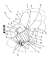
- FIGS. 9 and 10 show an alternative embodiment of the short-circuiting means 38.
- this is formed as a transverse to the longitudinal extent of the suction channel 14 aligned bristle strip 39, with metal bristles in the manner of a wire brush.
- a cleaning of the sensor part surfaces in the course of the up and Zuschwenkens the flap 25 is reached via this bristle strip 39.
- the sensor surfaces are brushed accordingly, so that any adhering dirt, especially moist dirt particles are removed.
- the bristle strip 39 accordingly serves in this embodiment at the same time as a checking means 40 as well as a cleaning agent 41.
- two respective acting on the flap 25 tension springs 32 are provided.
- only a centrally disposed tension spring 32 may be arranged.
- spring force is designed so that the flap 25 can be opened against the pending during operation vacuum.
- the control of the flap 25 for opening the secondary air opening 20 can also alternatively by an electric actuator, by means of solenoid, magnet, memory wire or weakening of a permanent magnet, by means of a servo motor or the like.
- an electric actuator by means of solenoid, magnet, memory wire or weakening of a permanent magnet, by means of a servo motor or the like.
- a mechanical solution for example in the form of a sponge, which loses its stability on contact with liquid or a powder, which dissolves immediately upon contact with liquid to trigger the locking of the secondary air opening.
Landscapes
- Engineering & Computer Science (AREA)
- Mechanical Engineering (AREA)
- Physics & Mathematics (AREA)
- Electromagnetism (AREA)
- Nozzles For Electric Vacuum Cleaners (AREA)
- Electric Vacuum Cleaner (AREA)
- Filtering Of Dispersed Particles In Gases (AREA)
Claims (9)
- Aspirateur (S) actionné par un moteur électrique, comportant une bouche d'aspiration (15) et un canal d'aspiration (14), un capteur d'humidité (17) étant disposé, en outre, dans le canal d'aspiration (14), caractérisé en ce que le canal d'aspiration (14) ouvre, dans le sens d'une ouverture d'air secondaire, lorsqu'une humidité est détectée.
- Aspirateur selon la revendication 1, caractérisé en ce que l'ouverture d'air secondaire (20) est prévue dans la zone associée au capteur d'humidité (17).
- Aspirateur selon l'une des revendications précédentes, caractérisé en ce qu'au cours du mouvement d'ouverture de l'ouverture d'air secondaire (20), un moyen de contrôle et/ou moyen de nettoyage (40, 41) opère en contact avec le capteur d'humidité (17).
- Aspirateur selon l'une des revendications précédentes, caractérisé en ce que l'accès à l'ouverture d'air secondaire (20) est atteint en rabattant une partie de la paroi (21) du canal d'aspiration.
- Aspirateur selon l'une des revendications précédentes, caractérisé en ce que la position de fermeture de l'ouverture d'air secondaire (20) est assurée par un aimant (36).
- Aspirateur selon l'une des revendications précédentes, caractérisé en ce que la position d'ouverture de l'ouverture d'air secondaire (20) est assistée par un ressort.
- Aspirateur selon l'une des revendications précédentes, caractérisé en ce que le capteur d'humidité (17) est réalisé sous la forme d'un capteur d'humidité capacitif.
- Aspirateur selon l'une ou plusieurs des revendications précédentes, caractérisé en ce que le capteur d'humidité (17) est constitué de deux parties (18) disposées à distance l'une de l'autre.
- Aspirateur selon l'une des revendications 5 à 8, caractérisé en ce que le moyen de contrôle (40) est constitué par un moyen de pontage (38) shuntant les parties (18) du capteur.
Applications Claiming Priority (1)
| Application Number | Priority Date | Filing Date | Title |
|---|---|---|---|
| DE200810021100 DE102008021100A1 (de) | 2008-04-28 | 2008-04-28 | Elektromotorisch betriebenes Saugreinigungsgerät |
Publications (3)
| Publication Number | Publication Date |
|---|---|
| EP2113184A2 EP2113184A2 (fr) | 2009-11-04 |
| EP2113184A3 EP2113184A3 (fr) | 2011-01-26 |
| EP2113184B1 true EP2113184B1 (fr) | 2015-05-20 |
Family
ID=40810256
Family Applications (1)
| Application Number | Title | Priority Date | Filing Date |
|---|---|---|---|
| EP20090157708 Active EP2113184B1 (fr) | 2008-04-28 | 2009-04-09 | Presse à comprimés rotative |
Country Status (6)
| Country | Link |
|---|---|
| EP (1) | EP2113184B1 (fr) |
| JP (1) | JP5363868B2 (fr) |
| CN (1) | CN101569514B (fr) |
| DE (1) | DE102008021100A1 (fr) |
| ES (1) | ES2538267T3 (fr) |
| TW (1) | TWI517825B (fr) |
Families Citing this family (17)
| Publication number | Priority date | Publication date | Assignee | Title |
|---|---|---|---|---|
| DE102010036772A1 (de) | 2010-07-30 | 2012-02-02 | Vorwerk & Co. Interholding Gmbh | Verfahren zur Überwachung einer Schließstellung |
| DE202011000366U1 (de) | 2011-02-17 | 2012-05-18 | Vorwerk & Co. Interholding Gmbh | Arbeitsgerät |
| DE102011050358B4 (de) | 2011-05-13 | 2022-02-17 | Vorwerk & Co. Interholding Gmbh | Gas-Strömungskanal, insbesondere Saugkanal eines Staubsaugers |
| DE102012108008A1 (de) | 2012-08-30 | 2014-03-06 | Miele & Cie. Kg | Selbstfahrendes Sauggerät und Verfahren zum Betreiben eines selbstfahrenden Sauggeräts |
| KR102054689B1 (ko) * | 2013-01-31 | 2020-01-22 | 삼성전자주식회사 | 청소 로봇 및 그 제어 방법 |
| JP6625394B2 (ja) * | 2015-10-22 | 2019-12-25 | オリンパス株式会社 | 挿入機器、挿入システム |
| CN106137021A (zh) * | 2016-07-12 | 2016-11-23 | 张学衡 | 一种断桥铝门窗清洁机器人 |
| JP2018143649A (ja) * | 2017-03-08 | 2018-09-20 | オムロン株式会社 | 自走式移動体、湿度センサ、および液体検出装置 |
| WO2019212177A1 (fr) | 2018-04-30 | 2019-11-07 | 엘지전자 주식회사 | Buse d'aspirateur |
| WO2019212187A1 (fr) | 2018-04-30 | 2019-11-07 | 엘지전자 주식회사 | Buse d'appareil de nettoyage |
| CN116269038A (zh) | 2018-04-30 | 2023-06-23 | Lg电子株式会社 | 清洁器吸嘴 |
| KR102711296B1 (ko) | 2018-04-30 | 2024-09-30 | 엘지전자 주식회사 | 청소기의 노즐 |
| CN114504271B (zh) | 2018-04-30 | 2023-11-28 | Lg电子株式会社 | 清洁器 |
| CN108836200A (zh) * | 2018-06-14 | 2018-11-20 | 宁波富佳实业有限公司 | 具有进水自我断电保护装置的拖地机 |
| KR102625905B1 (ko) | 2018-07-30 | 2024-01-18 | 엘지전자 주식회사 | 청소기의 노즐 |
| DE102018126109A1 (de) * | 2018-10-19 | 2020-04-23 | Vorwerk & Co. Interholding Gmbh | Messeinrichtung zur Verbindung mit einem Saugluftkanal eines Saugreinigungsgerätes |
| PL4385378T3 (pl) | 2022-12-15 | 2025-09-01 | BSH Hausgeräte GmbH | Odkurzacz |
Family Cites Families (7)
| Publication number | Priority date | Publication date | Assignee | Title |
|---|---|---|---|---|
| JPS507727U (fr) * | 1973-05-21 | 1975-01-27 | ||
| JPH0632536Y2 (ja) * | 1987-02-10 | 1994-08-24 | 株式会社ユニシアジェックス | 電磁弁 |
| DE8915511U1 (de) * | 1989-08-10 | 1990-08-23 | Progress Elektrogeräte GmbH, 7440 Nürtingen | Vorrichtung zum Schutz von Ansauggebläsen vor Wasserschäden |
| JPH0428327A (ja) * | 1990-05-23 | 1992-01-30 | Tokyo Electric Co Ltd | 電気掃除機 |
| JPH04210032A (ja) * | 1990-12-03 | 1992-07-31 | Matsushita Electric Ind Co Ltd | 電気掃除機 |
| JP2005224264A (ja) * | 2004-02-10 | 2005-08-25 | Funai Electric Co Ltd | 自走式掃除機 |
| JP4736644B2 (ja) * | 2005-09-06 | 2011-07-27 | パナソニック株式会社 | 電気掃除機 |
-
2008
- 2008-04-28 DE DE200810021100 patent/DE102008021100A1/de not_active Withdrawn
-
2009
- 2009-04-06 TW TW098111352A patent/TWI517825B/zh not_active IP Right Cessation
- 2009-04-09 ES ES09157708.0T patent/ES2538267T3/es active Active
- 2009-04-09 EP EP20090157708 patent/EP2113184B1/fr active Active
- 2009-04-27 JP JP2009107372A patent/JP5363868B2/ja not_active Expired - Fee Related
- 2009-04-28 CN CN200910132194.XA patent/CN101569514B/zh active Active
Also Published As
| Publication number | Publication date |
|---|---|
| CN101569514B (zh) | 2014-11-26 |
| JP5363868B2 (ja) | 2013-12-11 |
| JP2009261950A (ja) | 2009-11-12 |
| TW201002262A (en) | 2010-01-16 |
| EP2113184A2 (fr) | 2009-11-04 |
| CN101569514A (zh) | 2009-11-04 |
| DE102008021100A1 (de) | 2009-10-29 |
| ES2538267T3 (es) | 2015-06-18 |
| EP2113184A3 (fr) | 2011-01-26 |
| TWI517825B (zh) | 2016-01-21 |
Similar Documents
| Publication | Publication Date | Title |
|---|---|---|
| EP2113184B1 (fr) | Presse à comprimés rotative | |
| DE102010038095B4 (de) | Entleerungsstation für einen akkumulatorbetriebenen Elektrostaubsauger | |
| EP3310233B1 (fr) | Buse d'aspiration pour un aspirateur | |
| DE102013103086B4 (de) | Absaugstation für ein selbsttätig verfahrbares Bodenreinigungsgerät sowie Kombination einer Absaugstation mit einem solchen Gerät | |
| DE102009034955B4 (de) | Selbsttätig verfahrbares Bodenstaub-Aufsammelgerät | |
| EP2014212B1 (fr) | Association d'un suceur d'aspirateur et d'un chiffon, ainsi que chiffon et procédé de nettoyage humide de planchers | |
| EP2893860A1 (fr) | Appareil d'entretien du sol doté d'une brosse à rouleaux entraînée | |
| DE102015105059A1 (de) | Filteranordnung, Haushaltsgerät mit einer Filteranordnung und Verfahren zum Wechseln eines Filters | |
| DE102017127131A1 (de) | Regenerierbarer Staubsauger | |
| EP2380477B1 (fr) | Aspirateur électrique avec tubulure pour coopérer avec un sac à poussière | |
| DE102014119190A1 (de) | Saugdüse für einen elektromotorisch betriebenen Staubsauger | |
| DE212010000132U1 (de) | Zitzenbehandlungsvorrichtung | |
| DE102011050358B4 (de) | Gas-Strömungskanal, insbesondere Saugkanal eines Staubsaugers | |
| WO2014019620A1 (fr) | Machine de nettoyage des sols automotrice à module de système de filtre | |
| DE102012100457A1 (de) | Düse für einen Staubsauger | |
| DE102014116978A1 (de) | Reinigungsgerät mit einem durch einen Motor angetriebenen Gebläse und einem Saugkanal | |
| DE102010036772A1 (de) | Verfahren zur Überwachung einer Schließstellung | |
| EP2229856B1 (fr) | Appareil d'aspiration doté d'au moins un capteur | |
| DE3405749A1 (de) | Saugreinigungsgeraet | |
| DE102015105061B4 (de) | Reinigungsgerät | |
| DE102019102357B4 (de) | Vorrichtung zur Absperrung oder Steuerung des Durchflusses von schmutzbeladener Luft, Reinigungsgerät und Behältnis zum Abtrennen und/oder Sammeln von Schmutz mit einer solchen Vorrichtung | |
| EP0788760A2 (fr) | Dispositif d'enclenchement pour un aspirateur | |
| DE102015107877B4 (de) | Teppichbürstengerät | |
| DE102015101647B4 (de) | Saugdüse | |
| DE102020212052B3 (de) | Sammelbehälter für eine Reinigungsvorrichtung |
Legal Events
| Date | Code | Title | Description |
|---|---|---|---|
| PUAI | Public reference made under article 153(3) epc to a published international application that has entered the european phase |
Free format text: ORIGINAL CODE: 0009012 |
|
| AK | Designated contracting states |
Kind code of ref document: A2 Designated state(s): AT BE BG CH CY CZ DE DK EE ES FI FR GB GR HR HU IE IS IT LI LT LU LV MC MK MT NL NO PL PT RO SE SI SK TR |
|
| 17P | Request for examination filed |
Effective date: 20100607 |
|
| PUAL | Search report despatched |
Free format text: ORIGINAL CODE: 0009013 |
|
| AK | Designated contracting states |
Kind code of ref document: A3 Designated state(s): AT BE BG CH CY CZ DE DK EE ES FI FR GB GR HR HU IE IS IT LI LT LU LV MC MK MT NL NO PL PT RO SE SI SK TR |
|
| AX | Request for extension of the european patent |
Extension state: AL BA RS |
|
| D17P | Request for examination filed (deleted) | ||
| R17P | Request for examination filed (corrected) |
Effective date: 20110601 |
|
| 17Q | First examination report despatched |
Effective date: 20131108 |
|
| GRAP | Despatch of communication of intention to grant a patent |
Free format text: ORIGINAL CODE: EPIDOSNIGR1 |
|
| INTG | Intention to grant announced |
Effective date: 20141111 |
|
| GRAS | Grant fee paid |
Free format text: ORIGINAL CODE: EPIDOSNIGR3 |
|
| GRAA | (expected) grant |
Free format text: ORIGINAL CODE: 0009210 |
|
| AK | Designated contracting states |
Kind code of ref document: B1 Designated state(s): AT BE BG CH CY CZ DE DK EE ES FI FR GB GR HR HU IE IS IT LI LT LU LV MC MK MT NL NO PL PT RO SE SI SK TR |
|
| REG | Reference to a national code |
Ref country code: GB Ref legal event code: FG4D Free format text: NOT ENGLISH |
|
| REG | Reference to a national code |
Ref country code: CH Ref legal event code: EP |
|
| REG | Reference to a national code |
Ref country code: AT Ref legal event code: REF Ref document number: 727284 Country of ref document: AT Kind code of ref document: T Effective date: 20150615 |
|
| REG | Reference to a national code |
Ref country code: IE Ref legal event code: FG4D Free format text: LANGUAGE OF EP DOCUMENT: GERMAN |
|
| REG | Reference to a national code |
Ref country code: ES Ref legal event code: FG2A Ref document number: 2538267 Country of ref document: ES Kind code of ref document: T3 Effective date: 20150618 |
|
| REG | Reference to a national code |
Ref country code: DE Ref legal event code: R096 Ref document number: 502009011047 Country of ref document: DE |
|
| REG | Reference to a national code |
Ref country code: LT Ref legal event code: MG4D |
|
| REG | Reference to a national code |
Ref country code: NL Ref legal event code: MP Effective date: 20150520 |
|
| PG25 | Lapsed in a contracting state [announced via postgrant information from national office to epo] |
Ref country code: NO Free format text: LAPSE BECAUSE OF FAILURE TO SUBMIT A TRANSLATION OF THE DESCRIPTION OR TO PAY THE FEE WITHIN THE PRESCRIBED TIME-LIMIT Effective date: 20150820 Ref country code: LT Free format text: LAPSE BECAUSE OF FAILURE TO SUBMIT A TRANSLATION OF THE DESCRIPTION OR TO PAY THE FEE WITHIN THE PRESCRIBED TIME-LIMIT Effective date: 20150520 Ref country code: HR Free format text: LAPSE BECAUSE OF FAILURE TO SUBMIT A TRANSLATION OF THE DESCRIPTION OR TO PAY THE FEE WITHIN THE PRESCRIBED TIME-LIMIT Effective date: 20150520 Ref country code: FI Free format text: LAPSE BECAUSE OF FAILURE TO SUBMIT A TRANSLATION OF THE DESCRIPTION OR TO PAY THE FEE WITHIN THE PRESCRIBED TIME-LIMIT Effective date: 20150520 Ref country code: PT Free format text: LAPSE BECAUSE OF FAILURE TO SUBMIT A TRANSLATION OF THE DESCRIPTION OR TO PAY THE FEE WITHIN THE PRESCRIBED TIME-LIMIT Effective date: 20150921 |
|
| PG25 | Lapsed in a contracting state [announced via postgrant information from national office to epo] |
Ref country code: IS Free format text: LAPSE BECAUSE OF FAILURE TO SUBMIT A TRANSLATION OF THE DESCRIPTION OR TO PAY THE FEE WITHIN THE PRESCRIBED TIME-LIMIT Effective date: 20150920 Ref country code: BG Free format text: LAPSE BECAUSE OF FAILURE TO SUBMIT A TRANSLATION OF THE DESCRIPTION OR TO PAY THE FEE WITHIN THE PRESCRIBED TIME-LIMIT Effective date: 20150820 Ref country code: GR Free format text: LAPSE BECAUSE OF FAILURE TO SUBMIT A TRANSLATION OF THE DESCRIPTION OR TO PAY THE FEE WITHIN THE PRESCRIBED TIME-LIMIT Effective date: 20150821 Ref country code: LV Free format text: LAPSE BECAUSE OF FAILURE TO SUBMIT A TRANSLATION OF THE DESCRIPTION OR TO PAY THE FEE WITHIN THE PRESCRIBED TIME-LIMIT Effective date: 20150520 |
|
| PG25 | Lapsed in a contracting state [announced via postgrant information from national office to epo] |
Ref country code: EE Free format text: LAPSE BECAUSE OF FAILURE TO SUBMIT A TRANSLATION OF THE DESCRIPTION OR TO PAY THE FEE WITHIN THE PRESCRIBED TIME-LIMIT Effective date: 20150520 Ref country code: DK Free format text: LAPSE BECAUSE OF FAILURE TO SUBMIT A TRANSLATION OF THE DESCRIPTION OR TO PAY THE FEE WITHIN THE PRESCRIBED TIME-LIMIT Effective date: 20150520 |
|
| REG | Reference to a national code |
Ref country code: DE Ref legal event code: R097 Ref document number: 502009011047 Country of ref document: DE |
|
| PG25 | Lapsed in a contracting state [announced via postgrant information from national office to epo] |
Ref country code: RO Free format text: LAPSE BECAUSE OF NON-PAYMENT OF DUE FEES Effective date: 20150520 Ref country code: PL Free format text: LAPSE BECAUSE OF FAILURE TO SUBMIT A TRANSLATION OF THE DESCRIPTION OR TO PAY THE FEE WITHIN THE PRESCRIBED TIME-LIMIT Effective date: 20150520 Ref country code: SK Free format text: LAPSE BECAUSE OF FAILURE TO SUBMIT A TRANSLATION OF THE DESCRIPTION OR TO PAY THE FEE WITHIN THE PRESCRIBED TIME-LIMIT Effective date: 20150520 |
|
| PLBE | No opposition filed within time limit |
Free format text: ORIGINAL CODE: 0009261 |
|
| STAA | Information on the status of an ep patent application or granted ep patent |
Free format text: STATUS: NO OPPOSITION FILED WITHIN TIME LIMIT |
|
| REG | Reference to a national code |
Ref country code: FR Ref legal event code: PLFP Year of fee payment: 8 |
|
| 26N | No opposition filed |
Effective date: 20160223 |
|
| PG25 | Lapsed in a contracting state [announced via postgrant information from national office to epo] |
Ref country code: SI Free format text: LAPSE BECAUSE OF FAILURE TO SUBMIT A TRANSLATION OF THE DESCRIPTION OR TO PAY THE FEE WITHIN THE PRESCRIBED TIME-LIMIT Effective date: 20150520 |
|
| PG25 | Lapsed in a contracting state [announced via postgrant information from national office to epo] |
Ref country code: BE Free format text: LAPSE BECAUSE OF NON-PAYMENT OF DUE FEES Effective date: 20160430 |
|
| REG | Reference to a national code |
Ref country code: CH Ref legal event code: PL |
|
| GBPC | Gb: european patent ceased through non-payment of renewal fee |
Effective date: 20160409 |
|
| PG25 | Lapsed in a contracting state [announced via postgrant information from national office to epo] |
Ref country code: LU Free format text: LAPSE BECAUSE OF FAILURE TO SUBMIT A TRANSLATION OF THE DESCRIPTION OR TO PAY THE FEE WITHIN THE PRESCRIBED TIME-LIMIT Effective date: 20160409 |
|
| REG | Reference to a national code |
Ref country code: IE Ref legal event code: MM4A |
|
| PG25 | Lapsed in a contracting state [announced via postgrant information from national office to epo] |
Ref country code: CH Free format text: LAPSE BECAUSE OF NON-PAYMENT OF DUE FEES Effective date: 20160430 Ref country code: GB Free format text: LAPSE BECAUSE OF NON-PAYMENT OF DUE FEES Effective date: 20160409 Ref country code: LI Free format text: LAPSE BECAUSE OF NON-PAYMENT OF DUE FEES Effective date: 20160430 |
|
| REG | Reference to a national code |
Ref country code: FR Ref legal event code: PLFP Year of fee payment: 9 |
|
| PG25 | Lapsed in a contracting state [announced via postgrant information from national office to epo] |
Ref country code: IE Free format text: LAPSE BECAUSE OF NON-PAYMENT OF DUE FEES Effective date: 20160409 |
|
| PG25 | Lapsed in a contracting state [announced via postgrant information from national office to epo] |
Ref country code: NL Free format text: LAPSE BECAUSE OF FAILURE TO SUBMIT A TRANSLATION OF THE DESCRIPTION OR TO PAY THE FEE WITHIN THE PRESCRIBED TIME-LIMIT Effective date: 20150520 Ref country code: SE Free format text: LAPSE BECAUSE OF FAILURE TO SUBMIT A TRANSLATION OF THE DESCRIPTION OR TO PAY THE FEE WITHIN THE PRESCRIBED TIME-LIMIT Effective date: 20150520 |
|
| REG | Reference to a national code |
Ref country code: FR Ref legal event code: PLFP Year of fee payment: 10 |
|
| PG25 | Lapsed in a contracting state [announced via postgrant information from national office to epo] |
Ref country code: CY Free format text: LAPSE BECAUSE OF FAILURE TO SUBMIT A TRANSLATION OF THE DESCRIPTION OR TO PAY THE FEE WITHIN THE PRESCRIBED TIME-LIMIT Effective date: 20150520 Ref country code: HU Free format text: LAPSE BECAUSE OF FAILURE TO SUBMIT A TRANSLATION OF THE DESCRIPTION OR TO PAY THE FEE WITHIN THE PRESCRIBED TIME-LIMIT; INVALID AB INITIO Effective date: 20090409 |
|
| PG25 | Lapsed in a contracting state [announced via postgrant information from national office to epo] |
Ref country code: MT Free format text: LAPSE BECAUSE OF FAILURE TO SUBMIT A TRANSLATION OF THE DESCRIPTION OR TO PAY THE FEE WITHIN THE PRESCRIBED TIME-LIMIT Effective date: 20150520 Ref country code: TR Free format text: LAPSE BECAUSE OF FAILURE TO SUBMIT A TRANSLATION OF THE DESCRIPTION OR TO PAY THE FEE WITHIN THE PRESCRIBED TIME-LIMIT Effective date: 20150520 Ref country code: MC Free format text: LAPSE BECAUSE OF FAILURE TO SUBMIT A TRANSLATION OF THE DESCRIPTION OR TO PAY THE FEE WITHIN THE PRESCRIBED TIME-LIMIT Effective date: 20150520 Ref country code: MK Free format text: LAPSE BECAUSE OF FAILURE TO SUBMIT A TRANSLATION OF THE DESCRIPTION OR TO PAY THE FEE WITHIN THE PRESCRIBED TIME-LIMIT Effective date: 20150520 |
|
| PGFP | Annual fee paid to national office [announced via postgrant information from national office to epo] |
Ref country code: CZ Payment date: 20200330 Year of fee payment: 12 |
|
| PGFP | Annual fee paid to national office [announced via postgrant information from national office to epo] |
Ref country code: AT Payment date: 20200421 Year of fee payment: 12 |
|
| REG | Reference to a national code |
Ref country code: AT Ref legal event code: MM01 Ref document number: 727284 Country of ref document: AT Kind code of ref document: T Effective date: 20210409 |
|
| PG25 | Lapsed in a contracting state [announced via postgrant information from national office to epo] |
Ref country code: AT Free format text: LAPSE BECAUSE OF NON-PAYMENT OF DUE FEES Effective date: 20210409 Ref country code: CZ Free format text: LAPSE BECAUSE OF NON-PAYMENT OF DUE FEES Effective date: 20210409 |
|
| P01 | Opt-out of the competence of the unified patent court (upc) registered |
Effective date: 20230517 |
|
| PGFP | Annual fee paid to national office [announced via postgrant information from national office to epo] |
Ref country code: DE Payment date: 20250417 Year of fee payment: 17 |
|
| PGFP | Annual fee paid to national office [announced via postgrant information from national office to epo] |
Ref country code: ES Payment date: 20250519 Year of fee payment: 17 |
|
| PGFP | Annual fee paid to national office [announced via postgrant information from national office to epo] |
Ref country code: IT Payment date: 20250430 Year of fee payment: 17 |
|
| PGFP | Annual fee paid to national office [announced via postgrant information from national office to epo] |
Ref country code: FR Payment date: 20250422 Year of fee payment: 17 |